 Open Access Article
Creative Commons Attribution 3.0 Unported Licence
Suppression of byproduct accumulation in rechargeable aluminum–air batteries using non-oxide ceramic materials as air cathode materials
Ryohei
Mori
 *
*
Fuji Pigment Co., Ltd, 2-23-2 Obana, Kawanishi city, Hyogo Prefecture 666-0015, Japan. E-mail: moriryohei@fuji-pigment.co.jp; Fax: +81-72-759-9008; Tel: +81-72-759-8501
First published on 12th May 2017
Abstract
To develop a high-capacity rechargeable aluminum–air battery with resistance toward the degradation induced by long-term charge–discharge electrochemical reactions, non-oxide ceramic materials, e.g., TiN, TiC, and TiB2, were used as air cathode materials with the ionic liquid 1-ethyl-3-methylimidazolium chloride as the electrolyte. These non-oxide materials served as air cathode materials, and the addition of conductive carbon to these air cathode materials enhanced electrochemical reactions. The accumulation of byproducts, e.g., Al(OH)3 and Al2O3, has been a major obstacle in obtaining a stable rechargeable aluminum–air battery for practical applications, and the use of TiC and TiN as air cathodes led to the suppression of these accumulated byproducts. When TiC was used as an air cathode material, the battery exhibited long term stability. To the best of our knowledge, this is the first report of the suppression of the accumulation of such byproducts on both the anode and the air cathode.
Introduction
Metal–air batteries, consisting of a metal anode and an air cathode, demonstrate promise as an energy storage technology, because of their high energy density; the energy density of such batteries is greater than that of the practical rechargeable lithium ion battery used currently. Active metals such as Li, Ca, Mg, Al, Fe, and Zn can be used as anode materials.1–3 Among these metals, aluminum is the most abundant metal in the earth's crust. In addition, because of its physical and chemical properties, Al is considered to be a highly attractive source of energy as the anode in a metal–air battery. The low atomic weight (28.98 g mol−1) and trivalent oxidation state of Al yield a low gram-equivalent weight (8.99), in addition to an ultra-high specific gravimetric capacity (2.89 A h g−1). Only lithium exhibits a slightly higher electrochemical equivalent value, 3.86 A h g−1, while Al exhibits the highest theoretical specific volumetric capacity (8.04 A h cm−3).4,5 However, studies reported on Li–air batteries have been mainly focused on the use of an artificial feed of O2 to the air cathode. In addition, these batteries need to be prepared and hermetically sealed under inert gas, whereas aluminum–air batteries can be prepared and used under an ambient atmosphere.6 These advantages, as well as the cost-effectiveness of aluminum, increase its appeal for use as an anode material in such battery systems.Nevertheless, the major obstacles in the application of Al-based batteries include a high corrosion rate, hydrogen evolution rate, and the accumulation of byproducts, e.g., Al2O3 and Al(OH)3, at the anode and cathode, especially in aqueous electrolytes.7–12 In this regard, various kinds of ionic-liquid-based electrolytes including 1-ethyl-3-methylimidazolium chloride,13–16 1-butyl-1-methylpyrrolidinium bis(trifluoromethylsulfonyl)imide, 1-ethyl-3-methylimidazolium bis(trifluoromethylsulfonyl)amide, and trihexyl tetradecyl phosphonium bis(trifluoromethylsulfonyl)imide have been investigated as electrolytes.17–19 Especially aluminium oxide or hydroxide has been successfully eliminated by applying 1-ethyl-3-methylimidazolium oligo-fluoro-hydrogenate as an electrolyte, by replacing the aluminium oxide layer with an Al–O–F layer. Shvartsev et al. exhibited that this newly built up layer restricts Al corrosion while enabling high rates of Al anodic dissolution.20,21 Nevertheless, byproducts are still observed with the use of ionic liquid based electrolytes on the air cathode, which inhibit further electrochemical reactions.13–19 On the other hand, non-oxide ceramic materials, e.g., nitride, carbide, oxynitride, and carbonitride, have been applied for use as cathodic materials for PEFCs (polymer electrolyte fuel cells) as well as Li–air and Zn–air batteries, due to their oxygen reduction reaction catalytic effect.22,23 For example, Sampath et al. had reported that air cathodes composed of titanium carbonitride (TiCN) nanostructures could exhibit excellent electrochemical performance for the oxygen reduction reaction in alkaline media for both primary and rechargeable zinc air batteries.24 However, these non-oxide materials have not been applied for use in aluminum–air batteries thus far. In this study, by the simple application of non-oxide ceramic materials for use as the air cathodes, the formation of byproducts was suppressed, especially on the air cathode, after the electrochemical reaction. To the best of our knowledge, this is the first report of the suppression of byproduct accumulation at the anode and cathode of an aluminum–air battery system.
Experimental
An aluminum board (Al A1050, 99.5% purity) was used as the anode. The air cathode was composed of air cathode material/conductive carbon/polyvinylidene difluoride (PVDF)/N-methylpyrrolidone solution (at 1![[thin space (1/6-em)]](https://www.rsc.org/images/entities/char_2009.gif) :
:![[thin space (1/6-em)]](https://www.rsc.org/images/entities/char_2009.gif) 0 or a ratio of 0.2
0 or a ratio of 0.2![[thin space (1/6-em)]](https://www.rsc.org/images/entities/char_2009.gif) :
:![[thin space (1/6-em)]](https://www.rsc.org/images/entities/char_2009.gif) 0.8
0.8![[thin space (1/6-em)]](https://www.rsc.org/images/entities/char_2009.gif) :
:![[thin space (1/6-em)]](https://www.rsc.org/images/entities/char_2009.gif) 4) on a nickel-mesh current collector. The air cathode materials used herein were activated carbon (AC), titanium nitride (TiN), titanium carbide (TiC), and titanium diboride (TiB2). To investigate the effect of using conductive carbon as an air cathode material, an air cathode sample with conductive carbon was also prepared (denoted as TiN (C, B2)–C). A mixture of 1-ethyl-3-methylimidazolium chloride and AlCl3 in a molar ratio of 1
4) on a nickel-mesh current collector. The air cathode materials used herein were activated carbon (AC), titanium nitride (TiN), titanium carbide (TiC), and titanium diboride (TiB2). To investigate the effect of using conductive carbon as an air cathode material, an air cathode sample with conductive carbon was also prepared (denoted as TiN (C, B2)–C). A mixture of 1-ethyl-3-methylimidazolium chloride and AlCl3 in a molar ratio of 1![[thin space (1/6-em)]](https://www.rsc.org/images/entities/char_2009.gif) :
:![[thin space (1/6-em)]](https://www.rsc.org/images/entities/char_2009.gif) 2 was used as the electrolyte. All chemicals were purchased from Sigma Aldrich Corporation (Saint Louis, USA), except conductive carbon, which was purchased from Denka Co. Ltd. Japan. Crystal phases of the anode were investigated by X-ray diffraction (XRD) on an RAD-RU diffractometer (Rigaku Corp., Tokyo, Japan) using Cu Kα radiation at 40 kV and 200 mA. X-ray photoelectron spectroscopy (XPS) measurements were carried out on a PHI5000 VersaProbe II spectrometer (Ulvac-Phi Inc. MN, USA). Peak decomposition of the complex lines was performed by the peak synthesis method using a mixed Gaussian–Lorentzian peak shape while minimizing the error between the actual data and the sum of the deconvoluted peaks.20 The morphology of the anode and cathode was observed using a field-emission scanning electron microscope (JSM-7610F, JEOL Ltd, Japan) with an acceleration voltage of 15 kV. The electrochemical performance was evaluated via galvanostatic measurements (SP-150; BioLogic, France). The measurements were performed in a readily hand made two-electrode configuration. The sample area exposed to the solution was controlled by the size of the air cathode. The measured area of the prepared aluminum–air battery was 1.0 cm2. The measurement was started one day after the addition of the electrolyte in order to make sure that the electrolyte penetrates into all parts in the battery. The aluminium anode and air cathode were pinched with a plastic clip. All electrochemical measurements were carried out under ambient atmospheric conditions without any forced air supply. The current density was normalized by the weight of the whole cathode. Cyclic voltammetry (CV) was carried out at a scan rate of 10 mV s−1.
2 was used as the electrolyte. All chemicals were purchased from Sigma Aldrich Corporation (Saint Louis, USA), except conductive carbon, which was purchased from Denka Co. Ltd. Japan. Crystal phases of the anode were investigated by X-ray diffraction (XRD) on an RAD-RU diffractometer (Rigaku Corp., Tokyo, Japan) using Cu Kα radiation at 40 kV and 200 mA. X-ray photoelectron spectroscopy (XPS) measurements were carried out on a PHI5000 VersaProbe II spectrometer (Ulvac-Phi Inc. MN, USA). Peak decomposition of the complex lines was performed by the peak synthesis method using a mixed Gaussian–Lorentzian peak shape while minimizing the error between the actual data and the sum of the deconvoluted peaks.20 The morphology of the anode and cathode was observed using a field-emission scanning electron microscope (JSM-7610F, JEOL Ltd, Japan) with an acceleration voltage of 15 kV. The electrochemical performance was evaluated via galvanostatic measurements (SP-150; BioLogic, France). The measurements were performed in a readily hand made two-electrode configuration. The sample area exposed to the solution was controlled by the size of the air cathode. The measured area of the prepared aluminum–air battery was 1.0 cm2. The measurement was started one day after the addition of the electrolyte in order to make sure that the electrolyte penetrates into all parts in the battery. The aluminium anode and air cathode were pinched with a plastic clip. All electrochemical measurements were carried out under ambient atmospheric conditions without any forced air supply. The current density was normalized by the weight of the whole cathode. Cyclic voltammetry (CV) was carried out at a scan rate of 10 mV s−1.
Results and discussion
Fig. 1 shows the cyclic voltammograms of the prepared batteries at the 1st, 5th, and 25th cycles between 0 and 2.0 V, which were obtained to characterize the redox reactions. Considering the TiN air cathode material, clear anodic or cathodic reaction peaks were not observed although a stable CV was observed over repeated cycles. On the other hand, when TiC was used as the air cathode, weak cathodic and anodic peaks were observed at approximately 1.5 V and 1.0 V, corresponding to the dissolution and deposition of aluminum on the anode, respectively.25 The anodic–cathodic electrochemical reaction was also stable for this system from repetitive CV tests, even after 25 cycles, confirming the stability of TiN and TiC as catalytic air cathode materials. Moreover, when TiB2 was used as the air cathode material, the electrochemical reaction was observed to be weaker, and the peaks were vague.26 Generally, the additional conductive carbon present in the air cathode led to the enhancement of current, although the anodic and cathodic electrochemical reactions were weakened for both TiN–C and TiC–C. The aluminum–air battery that used chloroaluminate ionic liquid as the electrolyte exhibited Lewis acid–base chemistry comparable to Brønsted acidity in water. Similar to the fact that the proton concentration controls the chemistry and electrochemistry in the aqueous solution, chloroacidity is the major determinant of speciation, reactivity, and electrochemistry in the ionic liquid. For a metal–air battery, the composition of the melt determines its chloroacidity. As the chloride donor undergoes stepwise Lewis acid–base reactions with the acid AlCl3, chloroaluminate anions form according to the following equilibrium reactions:| Cl−(l) + AlCl3(s) ↔ AlCl4−(l) k = 1.6 × 10¹⁹ | (1) |
| AlCl4−(l) + AlCl3(s) ↔ Al2Cl7−(l) k = 1.6 × 10³ | (2) |
| Al2Cl7−(l) + AlCl3(s) ↔ Al3Cl10−(l) k = 1.0 × 10 | (3) |
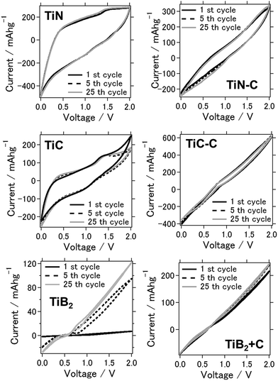 | ||
| Fig. 1 Cyclic voltammograms of the aluminum–air batteries for each air-cathode material (the air cathode material is mentioned in the figure). | ||
At <0.5 mole fraction of AlCl3 in the room-temperature liquid melt, the only anions present in significant quantities are the Lewis bases Cl− and AlCl4−, making the melt basic. At AlCl3 mole fractions greater than 0.5, as in our study, the only anions present in appreciable amounts in the liquid are AlCl4− and Al2Cl7−.16,29 This is a crucial factor because the electrodeposition of Al can only occur from Al2Cl7− as per the following reaction.27
| 4Al2Cl7− + 3e− → Al + 7AlCl4− | (4) |
Therefore, we hypothesize that Al2Cl7− functions as charge carriers on the anode in the aluminum–air battery.
The following reactions occur in the aqueous electrolyte during discharging:28
Anode:
| M → Mx+ + Xe− (M: metal) | (5) |
Air cathode:
| O2 + 2H2O + 4e− → 4OH− | (6) |
The following reactions occur during charging:
Anode:
| M+ + xe− → M | (7) |
Air cathode:
| 4OH− → O2 + 2H2O + 4e− | (8) |
The above metal reduction reaction is feasible in the case of a zinc–air battery with a KOH aqueous electrolyte. However, generally in the case of an aluminum–air battery, the reduction of Al3+ to Al is not possible in an aqueous electrolyte.4,5 Therefore, a suitable ionic liquid for use as an electrolyte in an aluminum–air battery is highly desired because of its ability to permit the deposition of Al.20
Considering the case of an Al–air battery with a suitable ionic liquid as the electrolyte, the following reactions occur upon discharging:
Anode:
| Al → Al3+ + 3e−E° = −1.68 V | (9) |
Cathode:
| 4Al3+ + 3O2 + 8e− → 2Al2O3E° = 1.56 V | (10) |
Subsequently, the following reactions may occur upon charging:
Anode:
| Al3+ + 3e− → Al E° = 1.68 V | (11) |
Cathode:
| 2Al2O3 → 4Al3+ + 3O2 + 8e−E° = −1.56 V | (12) |
The above Al reactions (eqn (6) and (8)) were possible in this study as a mixture of 1-ethyl-3-methylimidazolium chloride and AlCl3 was used as the electrolyte, and this point will be discussed in detail in the following section. However, reaction (9) could be difficult to proceed since the battery potential will be 3.24 V (cell potential = anodic potential + cathodic potential) and we have not observed that high potential in our experiment. In fact, as far as we know, not much study has clarified the exact mechanism of the air cathode reaction for aluminium air batteries with an ionic liquid based electrolyte. Thus, one should suggest that the oxygen reduction reaction is proceeding as we will show in the following section.
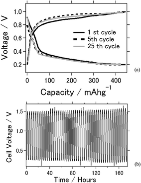
Fig. 2 shows the electrochemical properties of the battery using TiC as the air cathode. In the charge–discharge electrochemical reaction, TiC was used as the air cathode material as it exhibited a stable electrochemical reaction. Fig. 2(a) shows the charge–discharge curves at an applied current of ±0.5 mA cm−2. The capacities of the TiC battery at the 1st, 5th, and 50th cycles were 444, 432, and 424 mA h g−1, respectively. Approximately 95% of cell capacity is retained after 50 times of charge–discharge reaction. Fig. 2(b) shows the voltage versus time plot by the application of charge and discharge rates of ±2.0 mA cm−2 for 90 min each over a time. From this plot, the battery was clearly stable, with a long-term usability of approximately 1 week. From the results shown in Fig. 2(a) and (b), the cell capacity and cell durability for this battery are very stable after repeated electrochemical reactions under the ambient atmosphere. This crucial factor is expected to be beneficial when considering the practicality of a battery. As a stable electrochemical reaction was observed in the CV experiment, this result suggests that the cell capacity was also stable. Notably, the experimental cell capacity is still less than that of the theoretical value, and future studies should focus on its improvement.
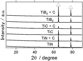
Fig. 3 shows the XRD patterns of the aluminum anode after the charge–discharge electrochemical reactions with the ionic liquid used in this study (1-ethyl-3-methylimidazolium chloride/AlCl3 mixture in a molar ratio of 1![[thin space (1/6-em)]](https://www.rsc.org/images/entities/char_2009.gif) :
:![[thin space (1/6-em)]](https://www.rsc.org/images/entities/char_2009.gif) 2) for the TiN, TiC, and TiB2 air cathodes. From this figure, aluminum hydroxide and aluminum oxide, which are typically the main byproducts of an aluminum–air battery and serve to inhibit long-term battery operation, were not observed. Similarly, byproducts have not been observed in previous studies with the use of an ionic liquid as the electrolyte in conjunction with other types of air cathode materials.16,20
2) for the TiN, TiC, and TiB2 air cathodes. From this figure, aluminum hydroxide and aluminum oxide, which are typically the main byproducts of an aluminum–air battery and serve to inhibit long-term battery operation, were not observed. Similarly, byproducts have not been observed in previous studies with the use of an ionic liquid as the electrolyte in conjunction with other types of air cathode materials.16,20
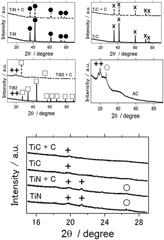
Fig. 4(a) shows the XRD patterns of the different air cathodes after the electrochemical reaction. With the use of activated carbon, TiB2, and TiB2–C as the air cathodes, the Al(OH)3 byproduct was observed in each case. In the case of activated carbon, Al2O3 was also detected. Upon close observation, a small amount of Al(OH)3 was observed for TiN- and TiC-based air cathodes (Fig. 4(b)). Notably, the TiN- and TiC-based aluminum–air battery samples were taken after more than 1 week of electrochemical reactions. Thus, although byproduct formation was not completely eliminated, to the best of our knowledge, this is the first report for the suppression of byproduct accumulation on the air cathode of an aluminum–air battery, which is beneficial when considering the practical use of these batteries.
In the ionic liquid, reactions (7) and (9) listed above may occur, which would result in the production of Al2O3. However, a different mechanism should have occurred since Al2O3 accumulation was suppressed. In an aqueous electrolyte or protic solvent, the oxygen reduction reaction proceeds via a multi-electron chemical reaction that occurs at the cathode of the battery with two main possible pathways: one involving the transfer of 2e− to produce peroxide (H2O2), and the other involving the production of water via direct 4e− transfer. These two pathways are expressed by eqn (10), (11) and (12), respectively:29
Direct 4e− pathway:
| O2 + 4H+ + 4e− → 2H2O | (13) |
2e− pathway:
| O2 + 2H+ + 2e− → 2H2O2 | (14) |
| 2H2O2 + 2H+ + 2e− → 2H2O | (15) |
1-Ethyl-3-methylimidazolium is an aprotic solvent so that the above oxygen reduction reaction is difficult to proceed due to the lack of protons in the solvent.30 However, the effect of humidity (water) should also be considered as 1-ethyl-3-methylimidazolium chloride is a hydrophilic ionic liquid; therefore, it absorbs the humidity from the ambient atmosphere, resulting in the presence of water in the electrolyte.16 It should be noted here that we have measured the water content in our ionic liquid based electrolyte by the Karl Fischer titration method and found that the water content was 2–3% at 1 day after 1-ethyl-3-methylimidazolium chloride and AlCl3 were mixed. However, it increases to 48–49% in 4 days and stays approximately at the same level. For comparison, we have conducted the same measurement for 1-butyl-3-methylimidazolium chloride and the water content stays at approximately 20–21% (data not shown). In addition, both metal nitride and carbide have been reported as excellent electrocatalysts for the oxygen reduction and evolution reactions involving the direct 4e− pathway.31,32 Thus, it is plausible that reactions (13)–(15) may proceed at the air cathode in our battery system. Furthermore, it is thought that at the TiN surface, peroxide formation involves the production of an intermediary superoxide ion (O2˙−), which is followed by protonation and electron transfer steps to produce H2O2 as follows:
| O2 + ˙ → O2˙ | (16) |
| O2˙ + (H+ + e−) → HO2˙ | (17) |
| HO2˙ + (H+ + e−) → H2O2˙ | (18) |
| H2O2˙ → H2O2 + ˙ | (19) |
However, they also explain that TiN is possible to catalyze both 2 and 4 electron reduction of oxygen which is beneficial to the catalytic properties of metal air batteries.33
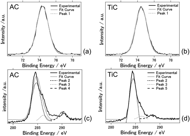
Fig. 5 shows the XPS spectra of the AC and TiC air cathodes following the electrochemical reactions. The charge–discharge electrochemical reaction at an applied current of ±0.5 mA cm−2 was conducted for 5 days. Fig. 5(a) and (b) present the Al 2p spectra and Fig. 5(c) and (d) indicate the C 1s spectra, for AC and TiC, respectively. The results are summarized in Table 1. Just one component (peak 1) was obvious for Al 2p photoelectron spectra. Peak 1 was located at a binding energy of 74.3–74.4 eV which was attributed to Al2O3 and Alx(OH)y species.21 This fact indicates that even byproducts such as Al2O3 and Alx(OH)y species were not detected by XRD measurements, and they exist on the TiC air cathode after the electrochemical reaction. Peak 2 indicates that carbon exists as carbon atoms. Peak 3 suggests that carbon exists as alcohol, or in the form of bonded with chloride. The latter seems more plausible since the electrolyte contains chloride. Peaks 2 and 3 were observed for both AC and TiC. On the other hand, carbon deposits on the AC air cathode in the form of carbonates whereas it exists as carboxyl form for the TiC air cathode.34 From these results, the accumulation of byproducts at the AC cathode possibly originates from aluminum carbonate. In fact aluminium carbonate is known to react with water or humidity to form aluminium hydroxide. Therefore, it may be possible that byproducts could originate from aluminium carbonate when the carbonaceous material is used as the air cathode. For the TiC air cathode, this chemical reaction was somehow suppressed when carbon exists as carboxyl groups in the air cathode. However, this speculation on the reasoning for byproduct accumulation needs to be further examined to reach a reasonable conclusion. It should be noted that a similar phenomenon has been observed in lithium air batteries. Muhammed et al. had reported that the TiC based air cathode reduces side reactions (arising from the electrolyte and electrode degradation) compared with the carbon based air cathode, and exhibits better reversible battery performance with decomposition of Li2O2. They suggest that the stability may originate from the presence of TiO2 (along with some TiOC) on the surface of TiC.35 Adams et al. had also reported that lithium carbonate, formate, and acetate are formed as a result of electrolyte decomposition during discharge for lithium air batteries with a carbon based air cathode.35 Therefore, aluminium carbonate could be formed as a result of electrolyte decomposition in the present aluminium air battery system. In addition, previous studies explain that the inert TiO2 layer on the titanium nitride/carbide surface suppresses the oxidation of the air cathode which results in high durability against detrimental air cathode oxidation when compared to carbon based air cathodes.35,36
| Sample | Peak | Binding energy (eV) | Compounds bonding | Peak area (%) |
|---|---|---|---|---|
| AC | Peak 1 | 74.3 | Al2O3/Alx(OH)y | 100 |
| TiC | Peak 1 | 74.4 | Al2O3/Alx(OH)y | 100 |
| AC | Peak 2 | 284.7 | Carbon | 83.9 |
| Peak 3 | 286.6 | Alcohol/C with Cl | 5.5 | |
| Peak 4 | 290.2 | Carbonates | 10.6 | |
| TiC | Peak 2 | 284.6 | Carbon | 87.8 |
| Peak 3 | 286.4 | Alcohol/C with Cl | 4.1 | |
| Peak 5 | 288.5 | Carboxyl | 8.1 |
Ignaszak et al. had suggested that one of the oxidation reactions to form a thin TiO2 film around the TiC particles is as follows37
| TiC + 5H2O → TiO2 + CO32− + 10H+ + 8e− | (20) |
Either way, detailed investigation of the TiC air cathode in our system remains to be further studied especially regarding the interaction with chloroaluminate in the electrolyte.
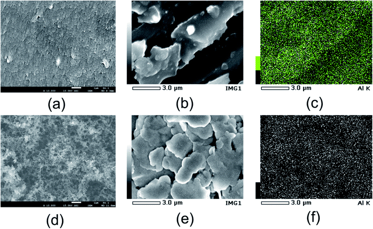
The morphology of the AC and TiC air cathode materials was examined. Fig. 6 shows the FE-SEM images of the AC and TiC air cathodes before and after the electrochemical reactions. For the air cathode samples after the electrochemical reaction, the image was recorded of the side facing the electrolyte. Fig. 6(a) and (d) show the FE-SEM images of the AC and TiC air cathodes before the electrochemical reactions, respectively. Fig. 6(b) shows the surface of the AC air cathode after the electrochemical reaction, and Fig. 6(c) shows the EDX mapping images of the Al atoms present in Fig. 6(b). Likewise, Fig. 6(e) shows the surface of the TiC air cathode after the electrochemical reaction, and Fig. 6(f) shows the EDX mapping image of the Al atoms present in Fig. 6(e). Basically, aluminum atoms were evenly located throughout the whole surface even there is a distinctive structure in the picture, indicating that byproducts such as Al(OH)3 or Al2O3 do not accumulate in the form of large crystals on the air cathode, even in the case of the AC air cathode, wherein Al(OH)3 or Al2O3 phases were detected by XRD (Fig. 4). Table 1 summarizes the atomic percentages of the observed samples. As a whole, the percentage of carbon atoms was large because a conductive carbon coating was applied to the sample surfaces for the purpose of SEM observation. The fluoride atoms corresponded to PVDF, which is a component material used in the fabrication of air cathodes. However, it is noticeable that the percentages of both aluminum and chloride were smaller for the TiC air cathode as compared to the AC air cathode following the electrochemical reaction, indicating that even though the existence of aluminum and chloride atoms is confirmed on the TiC air cathode, these atoms tend to accumulate to a greater extent on carbonaceous materials, such as activated carbon, than on non-oxide ceramic materials, such as titanium carbide. Furthermore, the atomic percentage ratio of chloride/aluminium is larger for TiN than AC, which could be the reason for less byproduct formation such as Al2O3 or Al(OH)3, due to the uneven ratio of chloride/aluminium.
Fig. 7(a) shows the Nyquist plot for the intact aluminum–air batteries with TiN as the air cathode before the occurrence of the electrochemical reaction. Fig. 7(b) shows the equivalent circuits for simulating this process, and Table 2 summarizes the simulation values obtained by using EC Lab software for the equivalent elements. Generally, R1 is regarded as the resistance of the electrolyte solution (Rs, resistance of the solution), and R2 is the resistance to the transfer of charge carriers at the electrode–electrolyte interface (Rc, resistance of charge transfer). R3 is regarded as the resistance of ion diffusion.38 When conductive carbon was added to the air cathode electrode, resistance was lower because of the enhanced conductivity in the batteries. As a whole, as compared to R1, R2 and R3 were found to be higher, and the degree of increase for these resistance values was more rapid with the progress of the electrochemical reaction. It may be suggested that even though the amounts of byproducts such as Al(OH)3 or Al2O3 are low, these byproducts contribute to the high resistance and resistance increase in the battery. For TiB2, the resistance and resistance increase were observed to be greater in comparison with those observed for the TiN- and TiC-based batteries, indicating that as Al(OH)3 is detected as a byproduct, the resistance and its increase are more dominant as compared with those of TiN- and TiC-based batteries (Table 3).
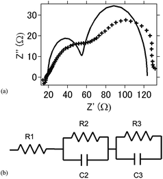 | ||
| Fig. 7 (a) Nyquist plot of the intact aluminum–air battery with the TiN air-cathode material before the electrochemical reaction. (b) Equivalent circuit of the present aluminum air battery. | ||
| Atom | (a) | (b) | (d) | (e) |
|---|---|---|---|---|
| C | 80.5 | 81 | 73.2 | 73 |
| O | 0.77 | 8.8 | 6.1 | 3.9 |
| F | 18.8 | 5.8 | 18.55 | 19 |
| AI | 1.7 | 0.1 | ||
| CI | 2.7 | 0.9 | ||
| Ti | 2.15 | 3.2 |
| 0 h | 24 h | 48 h | 72 h | |
|---|---|---|---|---|
| TiN | ||||
| R 1 (Ω cm2) | 9.866 | 11.35 | 13.43 | 14.92 |
| C 2 (F cm−2) | 1.13 × 10⁻³ | 8.35 × 10⁻³ | 2.45 × 10⁻² | 6.82 × 10⁻² |
| R 2 (Ω cm2) | 87.43 | 175.76 | 468.45 | 789.45 |
| C 3 (F cm−2) | 2.50 × 10⁻⁵ | 4.57 × 10⁻⁵ | 8.28 × 10⁻⁵ | 2.35 × 10⁻⁴ |
| R 3 (Ω cm2) | 69.43 | 75.43 | 86.58 | 107.54 |
| 0 h | 24 h | 48 h | 96 h | |
|---|---|---|---|---|
| TiN + C | ||||
| R 1 (Ω cm2) | 3.54 | 4.57 | 5.86 | 6.54 |
| C 2 (F cm−2) | 2.45 × 10⁻³ | 3.56 × 10⁻³ | 5.78 × 10⁻³ | 8.67 × 10⁻³ |
| R 2 (Ω cm2) | 67.83 | 89.54 | 128.54 | 151.65 |
| C 3 (F cm−2) | 3.75 × 10⁻⁵ | 8.45 × 10⁻⁵ | 6.65 × 10⁻⁴ | 7.23 × 10⁻⁴ |
| R 3 (Ω cm2) | 37.34 | 46.54 | 67.32 | 98.65 |
![[thin space (1/6-em)]](https://www.rsc.org/images/entities/char_2009.gif) |
||||
| TiC | ||||
| R 1 (Ω cm2) | 18.54 | 20.43 | 23.65 | 24.98 |
| C 2 (F cm−2) | 3.76 × 10⁻³ | 4.92 × 10⁻³ | 7.02 × 10⁻³ | 2.34 × 10⁻⁴ |
| R 2 (Ω cm2) | 97.43 | 136.65 | 167.54 | 198.35 |
| C 3 (F cm−2) | 6.95 × 10⁻⁵ | 7.28 × 10⁻⁵ | 9.65 × 10⁻⁵ | 2.04 × 10⁻⁵ |
| R 3 (Ω cm2) | 128.45 | 149.84 | 176.76 | 202.45 |
![[thin space (1/6-em)]](https://www.rsc.org/images/entities/char_2009.gif) |
||||
| TiC + C | ||||
| R 1 (Ω cm2) | 12.56 | 15.75 | 17.54 | 19.54 |
| C 2 (F cm−2) | 2.81 × 10⁻³ | 2.98 × 10⁻³ | 4.56 × 10⁻³ | 6.19 × 10⁻³ |
| R 2 (Ω cm2) | 68.34 | 96.07 | 112.65 | 139.65 |
| C 3 (F cm−2) | 2.71 × 10⁻⁵ | 3.26 × 10⁻⁵ | 4.76 × 10⁻⁵ | 6.58 × 10⁻⁵ |
| R 3 (Ω cm2) | 48.65 | 56.09 | 72.76 | 114.96 |
![[thin space (1/6-em)]](https://www.rsc.org/images/entities/char_2009.gif) |
||||
| TiB 2 | ||||
| R 1 (Ω cm2) | 34.65 | 45.65 | 49.32 | 52.76 |
| C 2 (F cm−2) | 3.76 × 10⁻² | 4.99 × 10⁻² | 6.29 × 10⁻² | 7.37 × 10⁻² |
| R 2 (Ω cm2) | 578.69 | 643.27 | 809.54 | 977.31 |
| C 3 (F cm−2) | 1.98 × 10⁻⁵ | 2.79 × 10⁻⁵ | 4.81 × 10⁻⁵ | 5.76 × 10⁻⁵ |
| R 3 (Ω cm2) | 34.86 | 48.21 | 68.43 | 98.65 |
![[thin space (1/6-em)]](https://www.rsc.org/images/entities/char_2009.gif) |
||||
| TiB 2 + C | ||||
| R 1 (Ω cm2) | 12.56 | 25.65 | 38.65 | 54.45 |
| C 2 (F cm−2) | 3.61 × 10⁻³ | 5.33 × 10⁻³ | 7.19 × 10⁻³ | 9.27 × 10⁻³ |
| R 2 (Ω cm2) | 85.54 | 120.82 | 143.99 | 187.54 |
| C 3 (F cm−2) | 1.68 × 10⁻⁵ | 2.81 × 10⁻⁵ | 3.17 × 10⁻⁵ | 5.47 × 10⁻⁵ |
| R 3 (Ω cm2) | 24.76 | 39.77 | 53.69 | 71.81 |
Conclusions
Non-ceramic oxide materials were used as air cathode materials, and TiN and TiC performed especially well in terms of increasing long-term battery operation and stable cyclic voltammograms. Moreover, when TiN and TiC were used as air cathode materials, the accumulation of byproducts, e.g., Al(OH)3 and Al2O3, was suppressed after the electrochemical reaction at the anode and air cathode. The clear reason for the suppression of byproduct accumulation is unknown at this stage and should be investigated further. It can be suggested that the adsorption/desorption of Al ions is readily feasible when TiN or TiC is used as the air cathode. Other types of nitride, carbide, oxynitride, and carbonitride materials that may suppress or even completely diminish the accumulation of byproducts should be investigated for the purpose of eventually creating a rechargeable aluminum–air battery for practical applications. In addition, since 1-ethyl-3-methylimidazolium chloride and AlCl3 are highly reactive towards humidity and water, this may be the problematic issue for the practical use of aluminium air batteries. A different chloro-free ionic liquid electrolyte such as 1-ethyl-3-methylimidazolium oligo-fluoro-hydrogenate should be investigated combined with air cathode materials composed of such non oxide ceramic materials, in order to create a rechargeable aluminium air battery for real use.References
- M. Kar, T. J. Simons, M. Forsythac and D. R. Macfarlane, Phys. Chem. Chem. Phys., 2014, 16, 18658–18674 RSC
.
- R. D. McKerracher, C. Ponce de Leon, R. G. A. Wills, A. A. Shah and F. C. A. Walsh, ChemPlusChem, 2015, 80, 323–335 CrossRef CAS
.
- F. Kitaura, H. Li and H. Zhou, Energy Environ. Sci., 2013, 6, 2302–2311 Search PubMed
.
- M. Nestoridi,
et al.
, J. Power Sources, 2008, 178, 445–455 CrossRef CAS
.
- D. R. Egan,
et al.
, J. Power Sources, 2013, 236, 293–310 CrossRef CAS
.
- K. N. Jung, J. Mater. Chem. A, 2014, 4, 14050–14068 Search PubMed
.
- R. Mori, RSC Adv., 2013, 3, 11547–11551 RSC
.
- R. Mori, RSC Adv., 2014, 4, 1982–1987 RSC
.
- R. Mori, RSC Adv., 2014, 4, 30346–30351 RSC
.
- R. Mori, J. Electrochem. Soc., 2015, 162, A288–A294 CrossRef CAS
.
- R. Mori, J. Appl. Electrochem., 2015, 45, 821–829 CrossRef CAS
.
- R. Mori, Journal of Electronic Materials, 2016, 45, 3375–3382 CrossRef CAS
.
- R. Revel, T. Audichon and S. Gonzalez, J. Power Sources, 2014, 272, 415–421 CrossRef CAS
.
- L. Geng, G. Lv, X. Xing and J. Guo, Chem. Mater., 2015, 27, 4926–4929 CrossRef CAS
.
- N. Jayaprakash, S. K. Das and L. A. Archer, Chem. Commun., 2011, 47, 12610–12612 RSC
.
- R. Mori, RSC Adv., 2017, 7, 6389–6395 RSC
.
- E. L. Zein, S. Abedin, E. Moustafa, R. Hempelmann, H. Natter and F. Endres, ChemPhysChem, 2006, 7, 1535–1543 CrossRef PubMed
.
- D. Gelman, B. Shvartsev and Y. E. Eli, Top. Curr. Chem., 2016, 374, 82–123 CrossRef PubMed
.
- M. Kar, T. J. Simons, M. Forsyth and D. R. MacFarlane, Phys. Chem. Chem. Phys., 2014, 16, 18658–18674 RSC
.
- D. Gelman, B. Shvartsev and Y. Ein-Eli, J. Mater. Chem. A., 2014, 2, 20237–20242 CAS
.
- B. Shvartsev, D. Gelman, D. Amram and Y. E. Eli, Langmuir, 2015, 31, 13860–13866 CrossRef CAS PubMed
.
- R. Ohnishi,
et al.
, J. Electrochem. Soc., 2013, 160, F501–F506 CrossRef CAS
.
- H. Ping, Y. Wang and Z. Haoshen, Chem. Commun., 2011, 47, 10701–10703 RSC
.
- V. G. Anju, R. Manjunatha, P. M. Austeria and S. Sampath, J. Mater. Chem. A, 2016, 4, 5258–5264 CAS
.
- T. Jiang,
et al.
, Surf. Coat. Technol., 2006, 201, 1–9 CrossRef CAS
.
- S. Yin,
et al.
, Appl. Catal., B, 2010, 93, 233–240 CrossRef CAS
.
- A. Bakkar and V. Neubert, Electrochim. Acta, 2013, 103, 211–218 CrossRef CAS
.
- P. C. Li,
et al.
, J. Power Sources, 2014, 269, 88–97 CrossRef CAS
.
- T. Poux,
et al.
, Catal. Today, 2012, 189, 83–92 CrossRef CAS
.
- N. Bogolowski and J. F. Drillet, ECS Trans., 2017, 75, 85–92 CrossRef
.
- M. Liu,
et al.
, Chem.–Eur. J., 2013, 19, 14781–14786 CrossRef CAS PubMed
.
- D. J. Ham and J. S. Lee, Energies, 2009, 2, 873–899 CrossRef CAS
.
- R. Ohnishi,
et al.
, J. Electrochem. Soc., 2013, 160, F501–F506 CrossRef CAS
.
- M. Descostes, F. Mercier, N. Thromat, C. Beaucaire and M. Gautier-Soyer, Appl. Surf. Sci., 2000, 165, 288–302 CrossRef CAS
.
- M. Muhammed,
et al.
, Nat. Mater., 2013, 12, 1050–1056 CrossRef PubMed
.
- B. D. Adams,
et al.
, ACS Nano, 2014, 8, 12483–12493 CrossRef CAS PubMed
.
- A. Ignaszak,
et al.
, Electrochim. Acta, 2012, 69, 397–405 CrossRef CAS
.
- M. Jingling, W. Jiuba, Z. Hongxi and L. Quanan, J. Power Sources, 2015, 293, 592–598 CrossRef CAS
.
| This journal is © The Royal Society of Chemistry 2017 |

