Photoinduced decoration of NiO nanosheets/Ni foam with Pd nanoparticles towards a carbon-free and self-standing cathode for a lithium–oxygen battery with a low overpotential and long cycle life†
Fan-Lu
Meng‡
ab,
Zhi-wen
Chang‡
ac,
Ji-jing
Xu
a,
Xin-bo
Zhang
 a and
Jun-min
Yan
 *b
*b
aState Key Laboratory of Rare Earth Resource Utilization, Changchun Institute of Applied Chemistry, Chinese Academy of Sciences, Changchun, 130022, P. R. China
bKey Laboratory of Automobile Materials, Ministry of Education and Department of Materials Science and Engineering, Jilin University, Changchun 130012, Jilin, China. E-mail: junminyan@jlu.edu.cn
cUniversity of Chinese Academy of Sciences, Beijing, 100049, P. R. China
First published on 25th January 2018
Abstract
Constructing an air electrode with a porous structure and tunable chemical composition can provide a solution to improve the performances of Li–O2 batteries. Herein, via a facile synthesis strategy by combining electrodeposition and photoreduction, we have fabricated a free-standing cathode with palladium (Pd)-modified NiO nanosheets (NS) grown on Ni foam (PNS). The Li–O2 battery with the PNS cathode delivers a high capacity (18![[thin space (1/6-em)]](https://www.rsc.org/images/entities/char_2009.gif) 900 mA h g−1 at 200 mA g−1), a much reduced charge overpotential (∼0.35 V), and a long-term cycling life (103 cycles at 200 mA g−1 and 1000 mA h g−1). These properties are due to the good activity of NiO/Pd catalyst, the highly porous structure of NiO nanosheets, and the absence of an organic binder. More importantly, film-like Li2O2 is formed via a surface growth pathway in the PNS cathode, providing a large contact area between the Li2O2 and cathode surfaces. As a benefit, the electron transfer during the charge process is facilitated, contributing to a much reduced charge overpotential.
900 mA h g−1 at 200 mA g−1), a much reduced charge overpotential (∼0.35 V), and a long-term cycling life (103 cycles at 200 mA g−1 and 1000 mA h g−1). These properties are due to the good activity of NiO/Pd catalyst, the highly porous structure of NiO nanosheets, and the absence of an organic binder. More importantly, film-like Li2O2 is formed via a surface growth pathway in the PNS cathode, providing a large contact area between the Li2O2 and cathode surfaces. As a benefit, the electron transfer during the charge process is facilitated, contributing to a much reduced charge overpotential.
Conceptual insightsLi–O2 batteries hold promise for outperforming today's lithium-ion batteries to deliver high energy density for otherwise unattainable applications. Carbon is a versatile cathode material with excellent performance, but it is unstable in the Li–O2 system. This problem can be in principle solved by replacing carbon with non-carbonaceous cathode materials. However, their high mass, small surface area and poor electrical conductivity usually lead to poor specific capacity. As an important step toward this goal, we have, for the first time, proposed a new concept of a carbon-free cathode for Li–O2 batteries – photoinduced decoration of NiO nanosheets/Ni foam with Pd nanoparticles. Unexpectedly, the resultant novel free-standing and carbon-free cathode endows the Li–O2 cell with excellent electrochemical performances, including an ultra-high specific capacity of 18![[thin space (1/6-em)]](https://www.rsc.org/images/entities/char_2009.gif) 900 mA h g−1 (more than 6 times that with other non-carbonaceous cathodes, typically <3000 mA h g−1), a low overpotential (350 mV) and a low cycle life (up to 103 cycles). These findings truly open up ways to tackle long-lingering problems associated with Li–O2 batteries with a practical and integrated solution. 900 mA h g−1 (more than 6 times that with other non-carbonaceous cathodes, typically <3000 mA h g−1), a low overpotential (350 mV) and a low cycle life (up to 103 cycles). These findings truly open up ways to tackle long-lingering problems associated with Li–O2 batteries with a practical and integrated solution.
|
As a promising candidate for next-generation energy storage, lithium–oxygen (Li–O2) batteries have attracted great attention in recent years owing to their extremely high theoretical energy density.1–4 Despite the bright future, the practical application of a Li–O2 battery is confronted by many problems, including a low round-trip efficiency and poor cycle life.5,6 To a considerable extent, all of these problems are closely associated with the sluggish reaction kinetics and inefficient mass transfer of O2 and Li+. Luckily, fabricating an efficient air cathode with a porous structure and tailored chemical compositions has provided a solution to these problems.7–9 In detail, the porous cathode can offer both interconnected channels for fast mass transfer of all reactants and large void volumes necessary for discharge product storage. And the tailored cathode composition can help in obtaining a desirable ORR/OER activity, thus accelerating the sluggish Li–O2 reaction kinetics.10,11 Based on these understandings, a Li–O2 battery with high performances can be obtained with the help of a smartly designed cathode.
So far, many efforts have been devoted towards fabricating cathodes with porous structures and tailored compositions. In this aspect, various cathode architectures, such as hierarchical mesoporous/macroporous carbon,12 a hierarchical-fibril CNT electrode,13 hierarchical carbon-architecture,14 3D porous N-doped graphene,15 have been reported. However, these carbonaceous cathodes can be oxidized in a harshly aggressive Li–O2 environment, generating parasitic products that degrade the Li–O2 battery performances.16,17 Under this circumstance, various transition metal oxides,18–23 which can resist oxidative corrosion, have been widely used for cathode construction in Li–O2 batteries. Among them, NiO shows high catalytic activity and the ability to oxidize the carbonate and carboxylate species side products generated during the battery reactions.24,25 Unfortunately, the poor ability of NiO to promote the formation/decomposition of Li2O2 has limited its application as a cathode material for Li–O2 batteries. As a remedy, it is desirable to deposit noble metals with excellent ORR and OER activity to increase the overall cathode activity.
With the above knowledge in mind, for the first time, we have fabricated a free-standing cathode with palladium (P)-modified NiO nanosheets (NS) grown on Ni foam (PNS) via a facile strategy by combining electrodeposition with photoreduction. As comparison groups, cathodes with NiO nanosheets (NS) grown on Ni foam (PNS) and a palladium (P)-modified NiO film (NF) grown on Ni foam (PNF) are also fabricated. In light of the results, these two cathodes exhibit little ORR performance. In sharp contrast, the PNS cathode exhibits a high specific capacity, relatively low overpotentials, good rate capability and a long cycling life. These superior performances are primarily the synergy of the hierarchically porous structure and the high catalytic activity of the PNS cathode. Further, the PNS cathode promotes the formation of film-like Li2O2via a surface-adsorption growth pathway, guaranteeing a large contact area between Li2O2 and the cathode. As a benefit, the electron transfer from Li2O2 to the cathode is facilitated, contributing to a low charge overpotential.
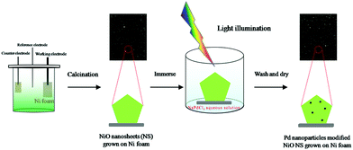
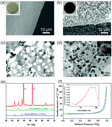
Fig. 1 schematically illustrates the synthesis strategy for the PNS cathode. The detailed synthesis process is described in the ESI.† The morphology and porous structure of the PNS cathode are investigated using field emission scanning electron microscopy (SEM) and transmission electron microscopy. As shown in Fig. 2a and b, without the help of any additional binder or solvent, porous NiO nanosheets are grown uniformly on the surface of the Ni foam, while the large pores of the Ni foam are kept intact, ensuring the formation of a free-standing structure and a favourable low-resistance pathway for electron transfer. As shown in Fig. 2c and d, the Pd nanoparticles (dark points) 4–6 nm in diameter, which serve as catalytically active centers for accelerating Li–O2 reactions, are uniformly deposited on the surfaces of the NiO nanosheets. In the inset of Fig. 2d, the HRTEM image shows the presence of Pd with a facet of (200) and NiO with a facet of (220), whose existence is further verified by the power X-ray diffraction (PXRD) results. As displayed in Fig. 2e, the diffraction peaks can be indexed to well-crystallized NiO (PDF no. 47-1049) and Pd nanoparticles (PDF no. 46-1043), which is further verified by the TEM mapping results in Fig. S1 (ESI†). To study the structure of the Pd/NiO cathode, we carried out the nitrogen absorption–desorption test. In light of the pore-size distribution (inset in Fig. 2f), both mesopores and macropores with a wide size range (∼5–100 nm) are clearly observed, being in agreement with the TEM results (Fig. 2c and d). This highly porous structure of the Pd/NiO cathode offers a high specific area of 20.53 m2 gPd/NiO−1, according to the nitrogen absorption–desorption isotherms (Fig. 2f), which offers a large cathode–electrolyte interface contact area to ensure high availability of the catalytically active sites in Li–O2 batteries. As comparison groups, the NS cathode (Fig. S2, ESI†) and the PNF cathode (Fig. S3, ESI†) are also investigated using SEM and XRD. Finally, this obtained PNS cathode simultaneously fulfils four key requirements for use as a Li–O2 battery cathode: good catalytic activity endowed by the Pd/NiO catalyst, a highly porous structure endowed by the NiO nanosheets, and the absence of an organic binder. All of these advantages are beneficial for the electrochemical performance of the Li–O2 batteries.
The electrochemical properties of the PNS, NS and PNF cathodes were then examined in a Li–O2 cell. As revealed in Fig. 3, the Li–O2 battery with the NS cathode exhibits an average discharge voltage plateau around 1.8 V, due to the little ORR performance of the NS cathode. On the other hand, the PNF cathode only delivers a capacity of around 1500 mA h g−1, which can be explained by the lack of enough triphase regions to promote the Li–O2 reactions and sufficient space for Li2O2 storage. Unlike the cases in the above two cathodes, the PNS cathode exhibits a desirable discharge capacity that is as high as 18,900 mA h g−1. Taken together, all of these results have demonstrated the importance of the catalytic composition and porous structure in promoting the Li–O2 reactions.
 | ||
| Fig. 3 The first discharge curves of Li–O2 cells with the (a) NS cathode, (b) PNF cathode and (c) PNS cathode. | ||
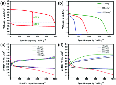
Based on this discovery, only the performances of the PNS cathode are evaluated. Fig. 4a shows the first discharge–charge voltage profiles of the Li–O2 battery with the PNS cathode at a current density of 200 mA g−1. Remarkably, the PNS cathode delivers a high discharge voltage plateau at ∼2.80 V and exhibits a much reduced charge voltage of around 3.4 V at the end of charging, realizing a round-trip efficiency that is as high as ∼82.4%. Note that the discharge and charge voltages of the Li–O2 battery can be significantly improved with the help of the PNS cathode, which enhances the round-trip efficiency that is vital for electrochemical energy storage devices. Then, the rate performance of the PNS cathode is evaluated. Fig. 4b shows that the Li–O2 battery with the PNS cathode delivers capacities of 18![[thin space (1/6-em)]](https://www.rsc.org/images/entities/char_2009.gif) 900 mA h g−1, 9000 mA h g−1 and 3500 mA h g−1 under current densities of 200 mA g−1, 500 mA g−1 and 1000 mA g−1, respectively. Simultaneously, it is found that the background discharge capacity of the Ar-filled batteries is negligible within the voltage range (Fig. S4, ESI†). This result demonstrates that the discharge capacities of the Li–O2 battery are derived from the ORR. The above study evidences the superiority of the PNS cathode in promoting the formation and decomposition of Li2O2, encouraging us to investigate the cycling stability of the PNS cathode. The PNS cathode is tested with a capacity-limited cycle method. Fig. 4c presents the discharge–charge voltage profiles of the PNS cathode, which is tested at a current density of 200 mA g−1 with a fixed capacity of 1000 mA h g−1. Of note, the Li–O2 battery with the PNS cathode can realize a stable cycling of 103 times, with the terminal discharge and charge voltages being around 2.70 and 3.5 V (Fig. S5, ESI†), respectively. Even when the current density is increased to 500 mA g−1, the PNS cathode can still maintain a stable cycling of 67 times (Fig. 4d). All these results have shown good cycling stability of the PNS cathode, indicating its promising application as a cathode material for Li–O2 batteries.
900 mA h g−1, 9000 mA h g−1 and 3500 mA h g−1 under current densities of 200 mA g−1, 500 mA g−1 and 1000 mA g−1, respectively. Simultaneously, it is found that the background discharge capacity of the Ar-filled batteries is negligible within the voltage range (Fig. S4, ESI†). This result demonstrates that the discharge capacities of the Li–O2 battery are derived from the ORR. The above study evidences the superiority of the PNS cathode in promoting the formation and decomposition of Li2O2, encouraging us to investigate the cycling stability of the PNS cathode. The PNS cathode is tested with a capacity-limited cycle method. Fig. 4c presents the discharge–charge voltage profiles of the PNS cathode, which is tested at a current density of 200 mA g−1 with a fixed capacity of 1000 mA h g−1. Of note, the Li–O2 battery with the PNS cathode can realize a stable cycling of 103 times, with the terminal discharge and charge voltages being around 2.70 and 3.5 V (Fig. S5, ESI†), respectively. Even when the current density is increased to 500 mA g−1, the PNS cathode can still maintain a stable cycling of 67 times (Fig. 4d). All these results have shown good cycling stability of the PNS cathode, indicating its promising application as a cathode material for Li–O2 batteries.
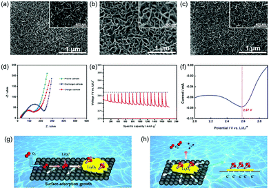
To understand the electrochemistry occurring in the Li–O2 battery with the PNS cathode, the morphologies of these discharged and charged cathodes were then investigated. After discharging the cell, the surface of the PNS cathode was uniformly covered with a muddy layer of Li2O2 (Fig. 5a and b), agreeing with previous results.26 After recharging, the discharge product Li2O2 disappears and the surface of the PNS cathode becomes clean again (Fig. 5c), revealing a good rechargeability of this cathode. To further confirm this point, the electrochemical impedance spectra (EIS) technique was then applied. As shown in Fig. 5d, compared with the impedance of the Li–O2 battery with the PNS cathode, that of the Li–O2 battery with the discharged PNS cathode increases significantly. This can be explained by the poor electronic conductivity of discharge products generated at the cathode site.27 Interestingly, the impedance of the Li–O2 battery with the charged PNS cathode could almost recover its initial value, indicating that the insulated discharge products can be fully decomposed during the charge process. These results are consistent with the SEM images discussed above, highlighting again the good rechargeability of the Li–O2 battery with the PNS cathode. Next, the galvanostatic intermittent titration technique (GITT) is also applied to investigate the electrochemical behaviour in the Li–O2 battery (Fig. 5e). The equilibrium potential of the Li–O2 battery is nearly 2.9 V, regardless of the state of discharge, demonstrating the formation of Li2O2.28,29
As mentioned above, at the end of the discharge process, film-like Li2O2 is formed on the surface of the PNS cathode. This finding led us to investigate inherent discharge mechanisms with the help of discharge linear scan voltammograms (LSVs). From Fig. 5f, only one peak at ∼2.57 V emerges, indicating the surface-adsorption growth pathway of Li2O2.2 As illustrated in Fig. 5g, the surface of the PNS cathode is speculated to possess a strong surface binding energy toward the superoxide species. Consequently, the growth of Li2O2 mainly takes place on the cathode surface, generating film-like Li2O2. As a bonus, a large contact area between the cathode and the discharge product is provided, thus benefitting the electron transfer from the Li2O2 to the cathode (Fig. 5h). Of note, in a real system, Li2O2 growth/decomposition is more complicated, and further studies using a combination of electrochemical and theoretical approaches are in progress to elucidate the exact functions of the PNS cathode.
Conclusions
In conclusion, the structural design and composition optimization of cathodic materials are key issues in the development of high performance Li–O2 batteries. In this work, we first developed an effective free-standing cathode with palladium (P)-modified NiO nanosheets (NS) grown on Ni foam (termed the PNS cathode). Compared with the NS cathode and the PNF cathode, the PNS cathode is advantageous in the following aspects. It possesses a hierarchical porous structure that act as pathways for fluent mass transfer (Li ion migration and O2 diffusion in the charge/discharge process) and provide sufficient room for storing the discharge product. Simultaneously, the deposition of Pd nanoparticles has increased the ORR and OER activity. The Li–O2 battery with this PNS cathode delivers a high discharge capacity (18![[thin space (1/6-em)]](https://www.rsc.org/images/entities/char_2009.gif) 900 mA h g−1 at 200 mA g−1), a much reduced charge overpotential (∼0.35 V) and a long-term cycling life (103 cycles at 200 mA g−1 and 1000 mA h g−1). The results also suggest that both the material and structure of the cathode should be optimized to simultaneously achieve a superior electrochemical performance of Li–O2 batteries.
900 mA h g−1 at 200 mA g−1), a much reduced charge overpotential (∼0.35 V) and a long-term cycling life (103 cycles at 200 mA g−1 and 1000 mA h g−1). The results also suggest that both the material and structure of the cathode should be optimized to simultaneously achieve a superior electrochemical performance of Li–O2 batteries.
Conflicts of interest
There are no conflicts to declare.Acknowledgements
This work is supported in part by National Natural Science Foundation of China (51522101, 51631004, and 51471075); Program for JLU Science and Technology Innovative Research Team (2017TD-09); and the Fundamental Research Funds for the Central Universities.Notes and references
- L. Johnson, C. Li, Z. Liu, Y. Chen, S. A. Freunberger, P. C. Ashok, B. B. Praveen, K. Dholakia, J.-M. Tarascon and P. G. Bruce, Nat. Chem., 2014, 6, 1091–1099 CrossRef CAS PubMed
.
- N. B. Aetukuri, B. D. McCloskey, J. M. Garcia, L. E. Krupp, V. Viswanathan and A. C. Luntz, Nat. Chem., 2014, 7, 50–56 CrossRef PubMed
.
- X. Gao and Y. Chen, Nat. Mater., 2016, 15, 882–888 CrossRef CAS PubMed
.
- L. Johnson, C. Li, Z. Liu, Y. Chen, S. A. Freunberer, P. C. Ashok, B. B. Praveen, K. Dholakia, J. Tarascon and P. G. Bruce, Nat. Chem., 2014, 6, 1091–1099 CrossRef CAS PubMed
.
- T. Liu, M. Leskes, W. Yu, A. J. Moore, L. Zhou, P. M. Bayley, G. Kim and C. P. Grey, Science, 2015, 350, 530–533 CrossRef CAS PubMed
.
- H.-D. Lim, B. Lee, Y. Zheng, J. Hong, J. Kim, H. Gwon, Y. Ko, M. Lee, K. Cho and K. Kang, Nat. Energy, 2016, 1, 1–6 Search PubMed
.
- J.-J. Xu, Z.-W. Chang, Y.-B. Yin and X.-B. Zhang, ACS Cent. Sci., 2017, 3, 598–604 CrossRef CAS PubMed
.
- D. A. Agyeman, M. Park and Y.-M. Kang, J. Mater. Chem. A, 2017, 5, 22234–22241 CAS
.
- J. Lun, Y. J. Lee, X. Luo, K. C. Lau, M. Asadi, H.-H. Wang, S. Brombosz, J. Wen, D. Zhai, Z. Chen, D. J. Miller, Y. S. Jeong, J.-B. Park, Z. Z. Fang, B. Kumar, A. S-Khojin, Y.-K. Sun, L. A. Curtiss and K. Amine, Nature, 2016, 529, 377–382 CrossRef PubMed
.
- D. Su, D. H. Seo, Y. Ju, Z. Han, K. Ostrikov, S. Dou, H.-J. Ahn, Z. Peng and G. Wang, NPG Asia Mater., 2016, 8, e286 CrossRef
.
- J.-J. Xu, Z.-L. Wang, D. Xu, L.-L. Zhang and X.-B. Zhang, Nat. Commun., 2013, 4, 2438 Search PubMed
.
- Z. Guo, D. Zhou, X. Dong, Z. Qiu, Y. Wang and Y. Xia, Adv. Mater., 2013, 25, 5668–5672 CrossRef CAS PubMed
.
- H. D. Lim, K. Y. Park, H. Song, E. Y. Jang, H. Gwon, J. Kim, Y. H. Kim, M. D. Lima, R. O. Robles, X. Lepro, R. H. Baughman and K. Kang, Adv. Mater., 2013, 25, 1348–1352 CrossRef CAS PubMed
.
- Z. Zhang, J. Bao, C. He, Y. Chen, J. Wei and Z. Zhou, Adv. Funct. Mater., 2014, 24, 6826 CrossRef CAS
.
- C. Zhao, C. Yu, S. Liu, J. Yang, X. Fan, H. Huang and J. Qiu, Adv. Funct. Mater., 2015, 25, 6913–6920 CrossRef CAS
.
- M. M. O. Thotiyl, S. A. Freunberger, Z. Peng and P. G. Bruce, J. Am. Chem. Soc., 2013, 135, 494–500 CrossRef PubMed
.
- D. M. Itkis, D. A. Semenenko, E. Y. Kataev, A. I. Belova, V. S. Neudachina, A. P. Siroina, M. Havecker, D. Teschner, A. K. Gericke, P. Dudin, A. Barinov, E. A. Goodiin, Y. S. Horn and L. V. Yashna, Nano Lett., 2013, 13, 4697–4701 CrossRef CAS PubMed
.
- X. Hu, X. Han, Y. Hu, F. Cheng and J. Chen, Nanoscale, 2014, 6, 3522–3525 RSC
.
- Y.-F. Xu, Y. Chen, G.-L. Xu, X.-R. Zhang, Z. Chen, J.-T. Li, L. Huang, K. Amine and S.-G. Sun, Nano Energy, 2016, 28, 63–70 CrossRef CAS
.
- R. Madhu, V. Veeramani, S.-M. Chen, A. Manikandan, A.-Y. Lo and Y.-L. Chueh, ACS Appl. Mater. Interfaces, 2015, 7, 15812–15820 CAS
.
- X. Guo, P. Liu, J. Han, Y. Ito, A. Hirata, T. Fujita and M. Chen, Adv. Mater., 2015, 27, 6137–6143 CrossRef CAS PubMed
.
- W.-H. Ryu, T.-H. Yoon, S. H. Song, S. Jeon, Y. J. Park and I.-D. Kim, Nano Lett., 2013, 13, 4190–4197 CrossRef CAS PubMed
.
- K. Qiu, Y. Lu, D. Zhang, J. Cheng, H. Yan, J. Xu, X. Liu, J.-K. Kim and Y. Luo, Nano Energy, 2015, 11, 687–696 CrossRef CAS
.
- X. Zhang, Q. Zhang, Z. Zhang, Y. Chen, Z. Xie, J. Wei and Z. Zhou, Chem. Commun., 2015, 51, 14636–14639 RSC
.
- M. Hong, H. C. Choi and H. R. Byon, Chem. Mater., 2015, 27, 2234–2241 CrossRef CAS
.
- E. Yilmaz, C. Yogi, K. Yamanaka, T. Ohta, H. R. Byon, M. D. Radin, C. W. Monroe and D. J. Siegel, J. Phys. Chem. Lett., 2015, 6, 3017–3022 CrossRef PubMed
.
- M. D. Radin, C. W. Monroe and D. J. Siegel, J. Phys. Chem. Lett., 2015, 6, 3017–3022 CrossRef CAS PubMed
.
- H. K. Lim, H. D. Lim, K. Y. Park, D. H. Seo, H. Gwon, J. Hong, W. A. Goddard, III, H. Kim and K. Kang, J. Am. Chem. Soc., 2013, 135, 9733–9742 CrossRef CAS PubMed
.
- Z. H. Cui, X. X. Guo and H. Li, Energy Environ. Sci., 2015, 8, 182–187 CAS
.
Footnotes |
| † Electronic supplementary information (ESI) available. See DOI: 10.1039/c7mh01014a |
| ‡ These authors contributed equally to this work. |
| This journal is © The Royal Society of Chemistry 2018 |


