Ultrafast nano-structuring of superwetting Ti foam with robust antifouling and stability towards efficient oil-in-water emulsion separation†
Shuai
Yang‡
a,
Kai
Yin‡
 *ab,
Junrui
Wu
a,
Zhipeng
Wu
a,
Dongkai
Chu
c,
Jun
He
*a and
Ji-An
Duan
 b
b
aHunan Key Laboratory of Super Microstructure and Ultrafast Process, School of Physics and Electronics, Central South University, Changsha, 410083, China. E-mail: kaiyin@csu.edu.cn; junhe@csu.edu.cn
bThe State Key Laboratory of High Performance and Complex Manufacturing, College of Mechanical and Electrical Engineering, Central South University, Changsha 410083, China
cThe Institute of Optics, University of Rochester, Rochester, NY 14627, USA
First published on 13th July 2019
Abstract
Massive discharging of oily wastewater has a serious impact on the ecological environment and human health. However, the rapid development of an efficient separation membrane exhibiting anti-fouling and long-term stability for highly emulsified oily wastewater separation remains a challenge. Herein, a superwettable porous Ti foam was fabricated via a facile and ultrafast strategy of femtosecond laser direct writing. The obtained surface possessed numerous nanoparticle-covered nanoripple structures with intriguing superhydrophilicity and underwater superoleophobicity. Further, the laser-treated foam possessed high porosity and exhibited an excellent performance separating oil-in-water emulsions. A high permeation flux up to ∼1900 L m−1 h−1 was achieved, with a separation efficiency of >99% under a negative pressure (−5 kPa). Moreover, the as-prepared foam exhibited outstanding properties of anti-oil fouling and stability, indicating robust reusability for long-term separation application. This work may provide an efficient and low-cost route for overcoming future large-scale oily wastewater separation issues.
1. Introduction
With the rapid development of society and the economy, the discharge of oily wastewater has increased gradually in daily life and in industrial production, which has seriously threatened the ecosystem and the health of human beings.1–3 The two main types of oil–water mixtures are discrete oil–water mixtures, which are easily separated into two layers; and emulsified oil and water, where the oil droplets are typically less than 20 μm in diameter, and are difficult to separate.4,5 Therefore, the separation of emulsified oil and water has become a global challenge.6,7 Various traditional strategies have been used to separate oil–water mixtures, such as centrifugal separation, gravity separation, biological treatment, ultrasonic separation, coagulation and oil absorbance.8–13 However, these methods often require cumbersome processing and are typically inefficient, costly, and occasionally cause secondary pollution.The last twenty years has seen the development of micro/nanotechnologies, where many functional interface materials have been explored.14–23 Among these, superwetting membranes have superior characteristics for application toward separation of emulsified oil and water.24–29 Owing to their special wettability and suitable pore size, superwetting membranes possess the ability for high-efficiency oil–water separation.30 Zhang et al. fabricated a pine-branch-like TiO2 nanofibrous membrane via electrospinning and a hydro-thermal process, where the membrane could separate various highly corrosive acidic (pH <0), basic (pH >14), and salty oil-in-water emulsions.26 Chen et al. prepared a Co3O4 nano-needle steel mesh by a facile hydro-thermal synthesis and subsequent calcination method that separated alkaline and saline oil-in-water emulsions with high efficiency (above 99%) and high flux.27 Although these reports successfully fabricated membranes that separated emulsified oil and water, the membrane production processes are complex and time-consuming. Furthermore, the function of the membrane is weak. Therefore, the development of an efficient, simple preparation process to fabricate robust membranes for the separation of emulsified oil and water is urgently needed.
In this paper, a superwetting Ti foam that can be used for efficient separation of oil-in-water emulsions was prepared by one-step femtosecond laser processing. The laser-induced micro/nanostructured surface possessed superhydrophilic properties and underwater superoleophobic properties. As a result, the as-prepared Ti foam efficiently separated oily wastewater while exhibiting excellent antifouling and stability performances. We believe that this as-prepared Ti foam has potential applications in oil-in-water emulsion separation, microfluidic control and energy recovery.
2. Experimental section
2.1 Fabrication of robust Ti foam
Femtosecond laser processing has been widely used in the fabrication of micro/nanostructures,31–38 altering the wettability of material surfaces with a simple fabrication process.39–46 In this experiment, a Ti foam (thickness of ∼1 mm, purchased from Yierda electronical company, China) with dimensions 2.3 × 2.6 cm2 was fixed on a platform, whereupon a commercial high-repetition femtosecond laser system (PHAROS, LIGHT CONVERSION, Lithuania) beam was focused on the foam surface. The beam was controlled by a line-by-line scan processing using a two-mirror galvanometric apparatus (intelliSCAN III 14, SCANLAB, Germany) with an F-Theta lens (f = 100 mm). The laser beam was set to a repetition rate of 75 kHz and a pulse width of 250 fs at a central wavelength of 1030 nm. The laser power, scanning speed and processing path line spacing were controlled by a computer, whose optimum conditions obtained in this experiment were 8 W, 2.0 m s−1, 10 μm, respectively. Finally, the laser-processed samples were ultrasonically cleaned with distilled water. All of the experiments were carried out at room temperature.2.2 Oil-in-water emulsion separation experiment
Four types of homogeneous oil-in-water emulsions were prepared by ultrasonically mixing various oils (i.e., soybean oil, ether gasoline, diesel, and petroleum) and water together in a ratio of 5![[thin space (1/6-em)]](https://www.rsc.org/images/entities/char_2009.gif) :
:![[thin space (1/6-em)]](https://www.rsc.org/images/entities/char_2009.gif) 100 v/v for 1 h. The as-prepared Ti foam was pre-wetted and placed on a homemade separation instrument comprising two glass tubes connected at one open end with flanges fixed with screws. Next, the oil-in-water emulsion was poured into the separation instrument and the separated liquid was collected in a beaker. In addition, an interface was present on the lower side of the glass tube that was connected to a device to apply a negative pressure. The experiments were performed under varying pressures of 0 and −5 kPa.
100 v/v for 1 h. The as-prepared Ti foam was pre-wetted and placed on a homemade separation instrument comprising two glass tubes connected at one open end with flanges fixed with screws. Next, the oil-in-water emulsion was poured into the separation instrument and the separated liquid was collected in a beaker. In addition, an interface was present on the lower side of the glass tube that was connected to a device to apply a negative pressure. The experiments were performed under varying pressures of 0 and −5 kPa.
2.3 Characterization
The micro/nanostructures of the foam surface were observed using a scanning electron microscope (SEM, MIRA3 LMU, TESCAN, Czech Republic). Atomic force microscopy (AFM, nanoIR2 systems, ANASYS instruments, USA) and laser confocal microscopy (LCM, Axio LSM700 Zeiss, Germany) further characterized the surface morphology of the processed samples. Elemental analysis and elemental maps of the sample surface were obtained by energy-dispersive X-ray spectroscopy (EDS, TESCAN, Czech Republic). The water contact angle (WCA) in air and the oil contact angle (OCA) in water were observed using a contact-angle system (Biolin Scientific, Finland) featuring a high-speed camera that was capable of recording the rapid absorption of water droplets and the rolling process of oil droplets. Images of the oil-in-water emulsion before and after separation were obtained by optical microscopy (Keyence VHX −5000, Japan), and an oil measurement instrument analyzed the separation efficiency of the oil-in-water emulsions.3. Results and discussion
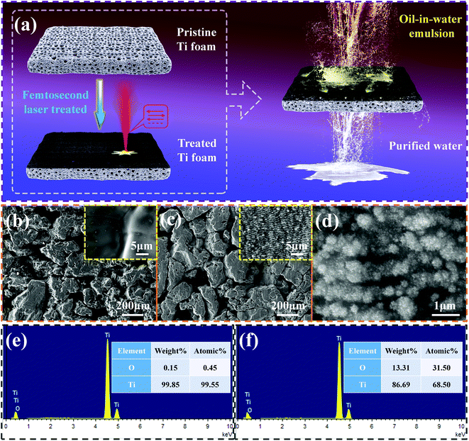
Fig. 1a shows a schematic of the laser ablation process on one side of the Ti foam. The laser beam was focused on the foam surface and a 2.3 × 2.6 cm2 region was fabricated via a line-by-line scanning process with a time cost of 45 s, which is the highest preparation efficiency of presently existing methods (Table S1 in ESI†). Fig. 1b–d show SEM images of the surface morphologies of the pristine (Fig. 1b) and laser-treated Ti foams (Fig. 1c and d). Comparing Fig. 1b and c, it is evident that the original Ti foam is porous with a smooth flat surface, becoming rough after the femtosecond laser treatment. A further increase in image resolution reveals many striped micro/nanostructures formed on the treated surface whereupon many nanoparticles are randomly distributed (Fig. 1d), which result in the surface appearing black after treatment. Finally, the laser-structured Ti foam patterns were uniformly formed on the treated area (Fig. S1 in ESI†). Fig. 1e and f exhibit the EDS elemental composition analysis of the Ti foam surface before and after laser ablation, where the oxygen content is observed to increase after laser treatment.The micro/nanostructures formed on the femtosecond laser-ablated foam surface were next investigated in more detail. Fig. 2a shows the LCM topography and skeleton map of the sample surface, revealing hundred-micrometer-scale flat blocks and dozens of micro-pores, where the latter facilitate the penetration of water through the sample. Details of the nanostructures are shown by AFM imaging (Fig. 2b), clearly showing the generated nanoripple structures on the block surface with depths of 100–200 nm and widths of 0.5–1 μm. Both the micro- and nanostructures contribute to the surface wettability characteristics.
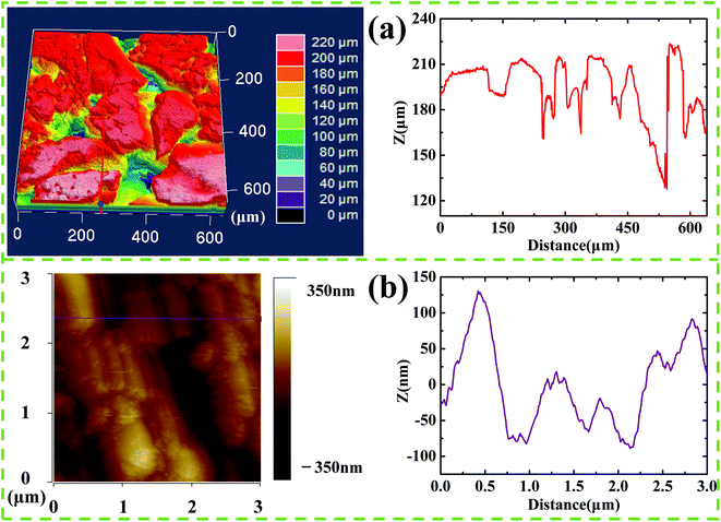 | ||
| Fig. 2 Surface morphology analysis of laser-treated Ti foam by (a) laser confocal microscopy and (b) atomic force microscopy, showing the topography (left) the corresponding skeleton maps (right). | ||
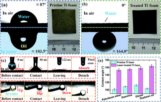
The wettability characteristics and optical images of the pristine and laser treated Ti foam are exhibited in Fig. 3a and b, respectively. The color of the sample surface turns black after femtosecond laser treatment, meanwhile the wettability of the sample is also obviously changed. The WCA for the pristine and laser-treated Ti foams were ∼87.0° and 0°, respectively, indicating that the wettability of the foam surface changes from hydrophilic to superhydrophilic with treatment. When the Ti foam was immersed in water, the OCA of the pristine and treated Ti foams were ∼103.5° and ∼164.0°, respectively, indicating that the underwater wettability of the samples has changed from oleophobic to superoleophobic with treatment. This unique wettability characteristic of superhydrophilicity with underwater superoleophobicity will facilitate the separation of oil-in-water emulsions. Fig. 3c shows the dynamic process of a 4 μL water droplet placed on the treated superhydrophilic surface, where it is quickly absorbed into the Ti foam surface (Movie S1 in ESI†). The underwater low oil adhesion of the treated superoleophobic foam surface is also verified in Fig. 3d, illustrating an underwater oil droplet controlled by a needle gradually connecting with the treated sample surface. The droplet is then slipped along the surface while the needle continues to exert an upward force, and finally the oil droplet leaves the sample surface and detaches with no residual oil on the sample surface. This phenomenon not only confirms that the treated Ti foam surface is superoleophobic in water, but also its extremely low adhesion to oil. In addition, the underwater OCAs of different oils on the pristine and treated Ti foams were explored, including petroleum, ether gasoline, diesel, and soybean oil, and the results are given in Fig. 3e. The different oils exhibit underwater OCAs ranging from 100–120° on the original Ti foam, and OCAs greater than 150° on the treated Ti foam surface. It is clear that the type of oil has little effect on the wettability, so the treated Ti foam has potential application for the separation of a variety of oil-in-water emulsions.
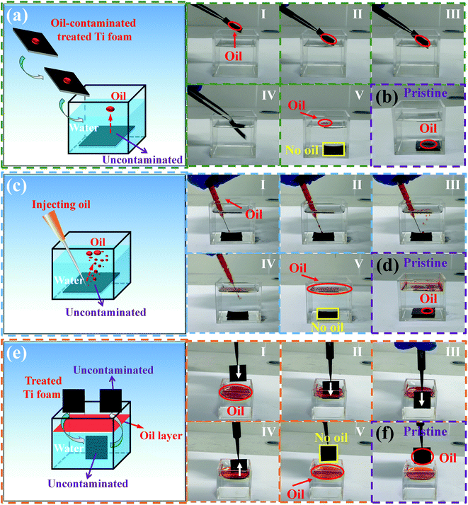
As reported above, the surface of the femtosecond laser-treated Ti foam exhibits underwater superoleophobicity and low oil adhesion, and the corresponding anti-oil fouling and self-cleaning performances is also important. Three methods for testing the anti-oil contamination properties of the sample surface are shown in Fig. 4, wherein the oil was dyed red with Sudan III for ease of observation. In the first test, an oil droplet was placed on the wet surface of the Ti foam sample, which was then submerged into clean water with the oily surface facing up. During this process using the femtosecond laser-treated Ti foam sample, the oil droplet separated from the surface and floated on the water surface because of the low oil adhesion of the treated surface (Fig. 4a and Movie S2 in ESI†). However, when the pristine Ti foam surface with an oil droplet was immersed in the water, the surface remained polluted with oil (Fig. 4b). In the second anti-fouling test, the Ti foam samples were submerged in water and a syringe with oil was used to spray oil on the underwater surface of the sample. Interestingly, the treated surface remained clean (Fig. 4c and Movie S3 in ESI†), while the pristine surface became polluted with an oil stain (Fig. 4d). In the final anti-fouling test, the pre-wetted Ti foam samples were immersed in an oily sewage and then removed from the sewage. It was found that the treated Ti foam surface was as clean as its pre-test state and was not polluted (Fig. 4e and Movie S4 in ESI†), while the pristine Ti foam surface was contaminated with oils (Fig. 4f). The above three anti-fouling experiments proved that the laser-treated surface possesses excellent oil resistance and a self-cleaning ability.
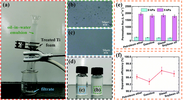
A self-made experimental device was constructed to verify the ability of the laser-treated Ti foam for oil-in-water emulsion separation (Fig. 5a). In this setup, the oil-in-water emulsion was poured into an upper glass tube separated from a lower glass tube by a membrane comprising the treated Ti foam. The emulsion in the upper glass tube flowed through the membrane and the resulting filtrate flowed from the lower glass tube into a beaker. To explore the oil content in the liquid before and after separation, optical microscope images of the oil-in-water emulsion (Fig. 5b) and the filtrate (Fig. 5c) were tested. Many small oil droplets with diameters less than 20 μm randomly distributed in the oil-in-water emulsion can be observed (Fig. 5b), while the filtrate appears clean with no oil droplets (Fig. 5c). Fig. 5d shows photographs comparing vials of the initial oil-in-water emulsion and the filtrate after separation, where it is clearly seen that the liquid becomes relatively transparent after separation. Several types of oil-in-water emulsions were prepared and used in the separation test (i.e., petroleum ether-in-water, gasoline-in-water, diesel-in-water, and soybean oil-in-water). The permeation flux of the four types of oil-in-water emulsions at normal atmospheric pressure (0 kPa) were found to be 205–260 L m−2 h−1, which was further improved to 1790–1950 L m−2 h−1 under the pressure of −5 kPa (Fig. 5e) and the surface structure remained stable after repeated tests (Fig. S2 in ESI†). It can be seen that applying an appropriate pressure improves the permeation flux of oil-in-water emulsion separation. In addition to permeation flux, another important index to evaluate the quality of oil-in-water emulsion separation is the separation efficiency, which was characterized herein by an oil measurement instrument. The oil rejection coefficient (R, %) can be calculated using47–51
Fig. 6 presents a possible theoretical explanation for the oil-in-water emulsion separation using laser-treated foam. First, a water film forms on the surface after pre-wetting owing to the superhydrophilicity of the as-prepared foam.52–54 Under the combined action of superhydrophilicity and superoleophobicity, the as-prepared surface prevents the small oil droplets from contacting the Ti foam, only allowing water to pass through the foam under the force of gravity and a downward capillary force driven by the superhydrophilicity.55–57 With the decrease of water content in the oil-in-water emulsion, the concentration of oil droplets begins to increase and the droplets accumulate and their size increases significantly. Finally, the water is filtered and the remaining oil forms a continuous phase, thus achieving the purpose of separating an oil-in-water emulsion.
 | ||
| Fig. 6 Schematic of the possible mechanism of the as-prepared Ti foam for oil-in-water emulsion separation. | ||
4. Conclusion
In this paper, an ultrafast and one-step strategy for fabrication of superwetting Ti foam via a femtosecond laser line-by-line scanning process is reported. The treated Ti foam surface exhibits superhydrophilicity in air and underwater superoleophobicity. As a consequence, it can be used for the separation of oil-in-water emulsions with high separation efficiency (above 99%). More importantly, the as-prepared foam possesses outstanding antifouling characteristics and stability for harsh environment applications. The as-prepared Ti foam herein combines numerous virtues that demonstrate its potential application for real-life oily wastewater treatment in industry and daily life.Conflicts of interest
The authors declare no competing financial interests.Acknowledgements
This research is supported by National Natural Science Foundation of China (Grant No. 51805553), the National Key R&D Program of China (Grant No. 2017YFB1104801), Natural Science Foundation of Hunan Province (Grant No. 2018JJ3666), the Project of State Key Laboratory of High Performance Complex Manufacturing, Central South University (Grant No. ZZYJKT2019-12).References
- J. Ge, L. A. Shi, Y. C. Wang, H. Y. Zhao, H. B. Yao, Y. B. Zhu, Y. Zhang, H. W. Zhu, H. A. Wu and S. H. Yu, Nat. Nanotechnol., 2017, 12, 434–440 CrossRef CAS PubMed
.
- C. H. Peterson, S. D. Rice, J. W. Short, E. Daniel, J. L. Bodkin, B. E. Ballachey and D. B. Irons, Science, 2003, 302, 2082–2086 CrossRef CAS PubMed
.
- G. N. Ren, Y. M. Song, X. M. Li, Y. L. Zhou, Z. Z. Zhang and X. T. Zhu, Appl. Surf. Sci., 2018, 428, 520–525 CrossRef CAS
.
- T. Tadros, P. Izquierdo, J. Esquena and C. Solans, Adv. Colloid Interface Sci., 2004, 108, 303–318 CrossRef PubMed
.
- A. K. Kota, G. Kwon, W. Choi, J. M. Mabry and A. Tuteja, Nat. Commun., 2012, 3, 1025 CrossRef PubMed
.
- G. Q. Li, H. Fan, F. F. Ren, C. Zhou, Z. Zhang, B. Xu, S. Z. Wu, Y. L. Hu, W. L. Zhu, J. W. Li, Y. S. Zeng, X. H. Li, J. R. Chu and D. Wu, J. Mater. Chem. A, 2016, 4, 18832–18840 RSC
.
- K. Yin, D. K. Chu, X. R. Dong, C. Wang, J. A. Duan and J. He, Nanoscale, 2017, 9, 14229–14235 RSC
.
- J. Rubio, M. L. Souza and R. W. Smith, Miner. Eng., 2002, 15, 139–155 CrossRef CAS
.
- L. X. Xu, Y. N. Chen, N. Liu, W. F. Zhang, Y. Yang, Y. Z. Cao, X. Lin, Y. Wei and L. Feng, ACS Appl. Mater. Interfaces, 2015, 7, 22264–22271 CrossRef CAS PubMed
.
- S. Y. Khew, C. F. Tan, H. P. Yan, S. D. Lin, E. S. Thian, R. Zhou and M. H. Hong, Appl. Surf. Sci., 2019, 465, 995–1002 CrossRef CAS
.
- B. Hervé, D. Thierry, T. D. G. Elisabeth and G. Frédéric, Chem. Rev., 2014, 114, 2694–2716 CrossRef PubMed
.
- P. Calcagnile, D. Fragouli, I. S. Bayer, G. C. Anyfantis, L. Martiradonna, P. D. Cozzoli, R. Cingolani and A. Athanassiou, ACS Nano, 2012, 6, 5413–5419 CrossRef CAS PubMed
.
- X. T. Zhu, J. W. Lu, X. M. Li, B. Wang, Y. M. Song, X. Miao, Z. J. Wang and G. N. Ren, Ind. Eng. Chem. Res., 2019, 58, 8148–8153 CrossRef CAS
.
- H. Chen, S. Q. Zhang, Z. X. Zhao, M. Liu and Q. R. Zhang, Prog. Chem., 2019, 4, 571–579 Search PubMed
.
- H. Li, K. Shin and G. Henkelman, J. Chem. Phys., 2018, 149, 174705 CrossRef PubMed
.
- F. Gao, J. Wang, H. W. Zhang, H. Jia, Z. Cui and G. Yang, J. Membr. Sci., 2019, 570–571, 156–167 CrossRef CAS
.
- H. Li, K. Shin and G. Henkelman, J. Phys. Chem. C, 2017, 121, 27504–27510 CrossRef CAS
.
- X. Li, S. F. Tang, D. L. Yuan, J. C. Tang, C. Zhang, N. Li and Y. D. Rao, Ecotoxicol. Environ. Saf., 2019, 177, 77–85 CrossRef CAS PubMed
.
- J. L. Wang, L. H. Tang, L. Y. Zhao and Z. E. Zhang, Energy, 2019, 172, 1066–1078 CrossRef
.
- L. Kang, H. L. Du, X. Du, H. T. Wang, W. L. Ma, M. L. Wang and F. B. Zhang, Desalin. Water Treat., 2018, 125, 296–301 CrossRef CAS
.
- H. Li, L. Luo, P. Kunal, C. S. Bonifacio, Z. Y. Duan, J. C. Yang, S. M. Humphrey, R. M. Crooks and G. Henkelman, J. Phys. Chem. C, 2018, 122, 2712–2716 CrossRef CAS
.
- C. Duan, F. Li, M. Yang, H. Zhang, Y. Wu and H. Xi, Ind. Eng. Chem. Res., 2018, 57, 15385–15394 CAS
.
- C. Duan, Y. Cao, L. Hu, D. Fu, J. Ma and J. Youngblood, J. Hazard. Mater., 2019, 373, 141–151 CrossRef CAS PubMed
.
- W. J. Ma, J. T. Zhao, O. Oderinde, J. Q. Han, Z. C. Liu, B. H. Gao, R. H. Xiong, Q. L. Zhang, S. H. Jiang and C. B. Huang, J. Colloid Interface Sci., 2018, 532, 12–23 CrossRef CAS PubMed
.
- X. Lin, F. Lu, Y. N. Chen, N. Liu, Y. Z. Cao, L. X. Xu, Y. Wei and L. Feng, ACS Appl. Mater. Interfaces, 2015, 7, 8108–8113 CrossRef CAS PubMed
.
- Y. Y. Zhang, Y. E. Chen, L. L. Hou, F. Y. Guo, J. C. Liu, S. S. Qiu, Y. Xu, N. Wang and Y. Zhao, J. Mater. Chem. A, 2017, 5, 16134–16138 RSC
.
- Y. E. Chen, N. Wang, F. Y. Guo, L. L. Hou, J. C. Liu, Y. Xu, Y. Zhao and J. Lei, J. Mater. Chem. A, 2016, 4, 12014–12019 RSC
.
- Z. Y. Luo, S. S. Lyu, Y. Q. Wang and D. C. Mo, Ind. Eng. Chem. Res., 2017, 56, 699–707 CrossRef CAS
.
- B. Jiang, Z. X. Chen, H. Z. Dou, Y. L. Sun, H. J. Zhang, Z. Q. Gong and L. H. Zhang, Appl. Surf. Sci., 2018, 456, 114–123 CrossRef CAS
.
- L. Hu, S. J. Gao, X. G. Ding, D. Wang, J. Jiang, J. Jin and L. Jiang, ACS Nano, 2015, 9, 4835–4842 CrossRef CAS PubMed
.
- K. Yin, C. Wang, J. A. Duan and C. L. Guo, Appl. Phys. A, 2016, 122, 834–837 CrossRef
.
- D. K. Chu, K. Yin, X. R. Dong, Z. Luo, Y. X. Song and J. A. Duan, Chin. Opt. Lett., 2018, 16, 011401 CrossRef
.
- K. Yin, S. Yang, X. R. Dong, D. K. Chu, J. A. Duan and J. He, Appl. Phys. Lett., 2018, 112, 243701 CrossRef
.
- J. L. Yong, Q. Yang, C. L. Guo, F. Chen and X. Hou, RSC Adv., 2019, 9, 12470–12495 RSC
.
- D. Pan, Z. Cai, S. Y. Ji, S. Y. Fan, P. R. Wang, Z. X. Lao, L. Yang, J. C. Ni, C. W. Wang, J. W. Li, Y. L. Hu, D. Wu, S. C. Chen and J. R. Chu, ACS Appl. Mater. Interfaces, 2018, 10, 36369–36376 CrossRef CAS PubMed
.
- J. A. Duan, X. R. Dong, K. Yin, S. Yang and D. K. Chu, Appl. Phys. Lett., 2018, 113, 203704 CrossRef
.
- K. Yin, S. Yang, J. R. Wu, Y. J. Li, D. K. Chu, J. He and J. A. Duan, J. Mater. Chem. A, 2019, 7, 8361–8367 RSC
.
- D. D. Han, Y. L. Zhang, Y. Liu, Y. Q. Liu, H. B. Jiang, B. Han, X. Y. Fu, H. Ding, H. L. Xu and H. B. Sun, Adv. Funct. Mater., 2015, 25, 4548–4557 CrossRef CAS
.
- F. Wang, C. F. Zhang, X. L. Yan, L. M. Deng, Y. F. Lu, M. Nastasi and B. Cui, J. Am. Ceram. Soc., 2018, 101, 4933–4941 CrossRef CAS
.
- K. Yin, H. F. Du, X. R. Dong, C. Wang, J. A. Duan and J. He, Nanoscale, 2017, 9, 14620–14626 RSC
.
- H. P. Yan, M. R. B. Rashid, F. P. Li and M. H. Hong, Appl. Surf. Sci., 2018, 427, 369–375 CrossRef CAS
.
- S. Yang, K. Yin, D. K. Chu, J. He and J. A. Duan, Appl. Phys. Lett., 2018, 113, 203701 CrossRef
.
- K. Yin, J. A. Duan, X. Y. Sun, C. Wang and Z. Luo, Appl. Phys. A, 2015, 119, 69–74 CrossRef CAS
.
- S. J. Jiang, Y. L. Hu, H. Wu, Y. C. Zhang, Y. Y. Zhang, Y. L. Wang, Y. H. Zhang, W. L. Zhu, J. W. Li, D. Wu and J. R. Chu, Adv. Mater., 2019, 1807507 CrossRef PubMed
.
- K. Yin, X. R. Dong, F. Zhang, C. Wang and J. A. Duan, Appl. Phys. Lett., 2017, 110, 121909 CrossRef
.
- K. Yin, J. A. Duan, C. Wang, X. R. Dong, Y. X. Song and Z. Luo, Appl. Phys. Lett., 2016, 108, 241601 CrossRef
.
- Z. X. Xue, S. T. Wang, L. Lin, L. Chen, M. J. Liu, L. Feng and L. Jiang, Adv. Mater., 2011, 23, 4270–4273 CrossRef CAS PubMed
.
- J. B. Fan, Y. Y. Song, S. T. Wang, J. X. Meng, G. Yang, X. L. Guo, L. Feng and L. Jiang, Adv. Funct. Mater., 2015, 25, 5368–5375 CrossRef CAS
.
- Z. X. Wang, S. Q. Ji, F. He, M. Y. Cao, S. Q. Peng and Y. X. Li, J. Mater. Chem. A, 2018, 8, 3391–3396 RSC
.
- N. Li, C. L. Yu, Y. F. Si, M. R. Song, Z. C. Dong and L. Jiang, ACS Appl. Mater. Interfaces, 2018, 10, 7504–7511 CrossRef CAS PubMed
.
- C. X. Li, L. Wu, C. L. Yu, Z. C. Dong and L. Jiang, Angew. Chem., Int. Ed., 2017, 56, 13623–13628 CrossRef CAS PubMed
.
- E. Barry, J. A. Libera, A. U. Mane, J. R. Avila, D. Devitis, K. V. Dyke, J. W. Elam and S. B. Darling, Environ. Sci.: Water Res. Technol., 2018, 4, 40–47 RSC
.
- E. Barry, A. U. Mane, J. A. Libera, J. W. Elam and S. B. Darling, J. Mater. Chem. A, 2017, 5, 2929–2935 RSC
.
- H. C. Yang, Y. S. Xie, H. Chan, B. Narayanan, L. Chen, R. Z. Waldman, S. K. R. S. Sankaranarayanan, J. W. Elam and S. B. Darling, ACS Nano, 2018, 12, 8678–8685 CrossRef CAS PubMed
.
- J. Wei, G. Zhang, J. Dong, H. T. Wang, Y. L. Guo, X. Zhuo, C. G. Li, H. Liang, S. H. Gu, C. H. Li, X. Y. Dong and Y. F. Li, ACS Sustainable Chem. Eng., 2018, 6, 11335–11344 CrossRef CAS
.
- J. F. Ou, B. Wu, M. S. Xue and F. J. Wang, Mater. Lett., 2019, 237, 134–136 CrossRef CAS
.
- B. B. Zhang, W. C. Xu, Q. J. Zhu, Y. T. Li and B. R. Hou, J. Colloid Interface Sci., 2018, 532, 201–209 CrossRef CAS PubMed
.
Footnotes |
| † Electronic supplementary information (ESI) available. See DOI: 10.1039/c9nr04381k |
| ‡ These authors contributed equally to the paper. |
| This journal is © The Royal Society of Chemistry 2019 |

