DOI:
10.1039/C8RA09645G
(Paper)
RSC Adv., 2019,
9, 2018-2025
Synthesis and photocatalytic activities of a CuO/TiO2 composite catalyst using aquatic plants with accumulated copper as a template
Received
23rd November 2018
, Accepted 21st December 2018
First published on 15th January 2019
Abstract
A CuO/TiO2 composite photocatalyst was synthesized by using a hydrolysis method. In the synthesis of the CuO/TiO2 composite catalyst, the aquatic plant Eichhornia crassipes containing accumulated copper was used and combined with titanium chloride precursor. X-ray diffraction (XRD), X-ray photoelectron spectroscopy (XPS), scanning electron microscopy (SEM), transmission electron microscopy (TEM), UV-Vis diffuse spectroscopy (DRS), and N2 adsorption–desorption isotherms were used for CuO/TiO2 characterization. The results showed that the CuO/TiO2 synthesized with Eichhornia crassipes as a template had smaller crystallite size (12.6 nm), higher specific surface area (109 m2 g−1), and higher pore volume (0.135 cm3 g−1). The catalytic activity of the CuO/TiO2 composite catalyst was also investigated by the degradation of phenol under ultraviolet (UV) and visible light irradiation, showing excellent catalytic activity. Complete removal of phenol was achieved at 80 and 120 min under UV and visible light sources, respectively. The catalytic performances may be due to the higher porosity and surface area of the composite catalyst. The Eichhornia crassipes aquatic plant also controls the crystal growth and prevents aggregation, which could enhance the catalytic activity. Moreover, the formation of the p–n CuO/TiO2 heterojunction also facilitates the separation of electrons and holes, and improves the photocatalytic activity of the material.
1. Introduction
Nowadays, the energy crisis and environmental pollution problems are current and global issues, and significant attention has been given to solving these problems by different methods.1–5 The application of suitable semiconductor materials for hydrogen production, CO2 reduction, pollutant degradation, and solar cells is also a current issue for scientists.6–10 In particular, treatment of industrial wastewater containing toxic heavy metals and aromatic organic pollutants has become a very big challenge for researchers.11–13 For this reason, researchers have tried to decontaminate wastewaters with the aid of different techniques, such as photocatalysis, biological, and other conventional methods.14–18 Among the techniques used, photocatalysis is a powerful method for the decontamination of wastewaters.19,20 The photocatalytic degradation of pollutants by using high performance semiconductor catalysts has been also confirmed as one of the most promising strategies to clean the environment.21
Currently, the remediation of environmental pollution is focused on using metal oxide based photocatalysts, and TiO2 has become a promising metal oxide photocatalytic material because of its stability and catalytic efficiency.22,23 However, the photocatalytic activities with TiO2 catalysts is typically suitable under UV irradiation owing to the large band gap energy (3.2 eV), and this limits TiO2 in practical applications.22–24 For this reason, researchers have tried to modify the TiO2 semiconductor material to be active in the visible region of the electromagnetic spectrum for different applications.25,26 Among the methods used for making TiO2 semiconductors active under visible light are doping, combination of TiO2 with other lower band gap metal oxides and others.27–29 In addition to doping or combination of TiO2 with other materials, the application of porous metal oxides has also many advantages in the remediation of environmental pollution.30,31 Reports have also shown that synthesized mesoporous TiO2 exhibits a high specific surface area and enhances the catalytic activity.32,33 For this purpose, biological renewable resources such as lignin and cellulose templates for the preparation of mesoporous metal oxide materials are significantly important for wastewater treatment, as reported by different researchers.34–36 Also, biotemplate methods for the synthesis of materials for the decontamination of wastewater are believed to be green and environment-friendly and so are favored by the scientific community.37–39
Recently, Chen et al. synthesized mesoporous TiO2 nanoparticles using the biological renewable resource unmodified lignin and N-doped mesoporous TiO2 nanoparticles with biological renewable nanocrystalline cellulose as template for photocatalytic degradation of pollutants.40,41 Zhou et al. synthesized TiO2 nanocubes induced by cellulose nanocrystals (CNCs) at low temperature.42 Moreover, Miao et al. prepared mesoporous TiO2 films using titanium tetrabutyloxide and cellulose.43 TiO2 immobilized on carbon materials derived from renewable and biodegradable resources and morph-TiO2 from green-leaf biotemplates have also been synthesized to enhance photocatalytic activity.34,44 However, utilization of the aquatic plant Eichhornia crassipes containing accumulated copper combined with TiO2 has not previously been reported.
In this paper, a CuO/TiO2 composite photocatalyst was prepared by a simple and green method using Eichhornia crassipes aquatic plant containing accumulated copper as a template. The effects of the Eichhornia crassipes template on the catalytic activity were studied systematically. Moreover, TiO2-Tep with the Eichhornia crassipes and without copper aqueous solution, and TiO2 without using the Eichhornia crassipes template were also prepared and used for comparison purposes. Commercially available P25-TiO2 was also compared with the synthesized composite catalyst. To investigate the catalytic activities of the materials under UV and visible light sources, phenol was used as pollutant. Hence, the synthesis of combined p-type CuO semiconductor from copper-enriched Eichhornia crassipes and n-type TiO2 semiconductor is expected to enhance the photocatalytic degradation of phenol under UV and visible light sources.
2. Experimental methods
2.1. Chemicals
All chemicals in this experiment were analytical grade and used without further purifications.
2.2. Preparation of template
In this experiment, the aquatic plant Eichhornia crassipes was used as a template. The plant was used after it had been immersed in 20 mg L−1 copper nitrate solution for one week. Then, the Eichhornia crassipes, which had accumulated copper, was dried and crushed to a particle size of about 100–120 mesh. Finally, the resulting crushed samples were collected and stored for further use.
2.3. Catalyst preparation
The composite catalyst was prepared with a simple and green method. In this particular procedure, 10 ml of TiCl4 was added dropwise into 200 ml solution containing 1 g L−1 Eichhornia crassipes with accumulated copper and stirred for 30 min. Subsequently, the solution was heated at 80 °C under continuous stirring. After stirring for 30 min, NH3·H2O was added dropwise into the solution in order to adjust the pH to 7. After stirring for another 30 min, the precipitate was aged for 10 h at room temperature. The resulting precipitate was washed with distilled water and anhydrous ethanol. Finally, the product was dried at 85 °C under vacuum for 24 h, and calcined at 500 °C for 2 h in air. Then, the CuO/TiO2 composite catalyst was obtained. For comparison purposes, TiO2-Tep made with Eichhornia crassipes and without copper aqueous solution, and TiO2 without using the Eichhornia crassipes template were prepared by similar procedures. Commercially available P25-TiO2 was also used for comparison in this experiment.
2.4. Characterizations
An X-ray diffraction (XRD) system (Rigaku diffractometer with Cu Kα radiation source) was used to examine the crystal structure of the photocatalytic composite material. Transmission electron microscopy (TEM, Tecnai G2 F20) with an accelerating voltage of 200 kV was used to observe the microstructure of the catalysts. X-ray photoelectron spectrometry measurement was conducted by means of a Physical Electronics PHI5700 photoelectron spectrometer with Al Kα (hv = 1486.6 eV) radiation source. The ultraviolet–visible diffuse reflectance spectra measurements were recorded using a TU-1901 UV-Vis spectrophotometer. N2 adsorption–desorption experiments were also performed using a SSA4300 analyzer after degassing for 2 h at 200 °C.
2.5. Catalyst activity measurements
The performance of the composite catalyst was tested in a home-made jacketed quartz reactor. A mercury lamp (8 W) was used as a source of UV light. A Xe lamp (350 W) with wavelength filtered to below 400 nm was used as a source of visible light. We used 250 ml of phenol solution (50 mg L−1) for the photocatalytic degradation test. In the reaction mixture, 0.125 g of the catalyst was used and the mixture was stirred for 30 min in the dark to obtain adsorption–desorption equilibrium. Air flow was supplied into the reactor throughout the reaction. Finally, a 5 ml aliquot of solution was taken out at intervals of 20 min from the reactor and centrifuged. Then, the supernatant was examined by using a TU-1901 UV-Vis spectrophotometer and concentration was calculated by means of the Lambert–Beer law.
3. Results and discussion
3.1. XRD analysis
The XRD diffraction patterns of the CuO/TiO2 composite, TiO2-Tep, and TiO2 annealed at 500 °C are shown in Fig. 1. As we see from Fig. 1, the characteristic peak positions of anatase and rutile at 25.27° and 27.48°, respectively, were not affected by the Eichhornia crassipes template. However, the amounts of rutile formed in the CuO/TiO2 composite and TiO2-Tep were smaller as compared with the template-free TiO2 after calcination at 500 °C. Thus, the transition from anatase to rutile was controlled by the Eichhornia crassipes template and the change was relatively difficult. Moreover, the average crystallite sizes of the catalysts calculated by means of the Scherrer formula are listed in Table 1. As we see from Table 1, the crystallite sizes of the CuO/TiO2 and TiO2-Tep were 12.6 and 12.3 nm, respectively. However, the crystallite size of the template-free TiO2 was 18.1 nm. This shows that the use of the Eichhornia crassipes template in the synthesis TiO2 nanoparticles made the crystallite size smaller. The smaller crystallite size may be due to the three-dimensional network of Eichhornia crassipes blocking the crystal growth. On the other hand, the functional groups on the surface of the Eichhornia crassipes template may bond with hydroxides of Ti which could limit agglomeration and inhibit the TiO2 transition from anatase to rutile.45 In addition to this, a smaller peak was also observed at about 35.4° due to the presence of CuO in the composite catalyst.
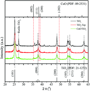 |
| | Fig. 1 XRD pattern of CuO/TiO2, TiO2-Tep, and TiO2 catalysts. | |
Table 1 Crystallite size and surface area of catalysts, and the kinetic parameters of phenol photocatalytic degradationa
| Sample |
Crystallite size/nm |
SBET/(m2 g−1) |
Phenol removalb/% |
k/min−1 |
R2 |
| k, reaction constant. At 80 min. |
| CuO/TiO2 |
12.6 |
109 |
100 |
0.1405 |
0.8782 |
| TiO2-Tep |
12.3 |
112 |
77.3 |
0.0694 |
0.8756 |
| TiO2 |
18.1 |
43.8 |
55.8 |
0.0323 |
0.9395 |
| P25-TiO2 |
21.0 |
50.0 |
64.1 |
0.0676 |
0.8898 |
3.2. XPS analysis
Fig. 2 shows the XPS spectra for the CuO/TiO2 composite and for TiO2 made without using the template. As we see from Fig. 2a, the high resolution Ti2p XPS spectra of CuO/TiO2 and TiO2, contain peaks located at 458.3 and 464.2 eV belonging to Ti2p3/2 and Ti2p1/2, respectively, of Ti4+. Fig. 2b shows the high resolution O1s XPS spectra of CuO/TiO2 and TiO2. The peaks at 529.6 and 531.3 eV belong to the lattice oxygen and the hydroxyl oxygen, respectively. Moreover, Fig. 2c shows the Cu2p XPS spectrum of the CuO/TiO2 composite catalyst. The peaks at 934.6 and 954.5 eV belong to Cu2p3/2 and Cu2p1/2, respectively, which indicates the formation of Cu2+ in the composite.46,47 The peaks at 944.2 eV and 963.8 eV are the satellite peaks for Cu2+. As we have seen from the results, the XPS and the XRD data further confirmed the formation of CuO in the composite.
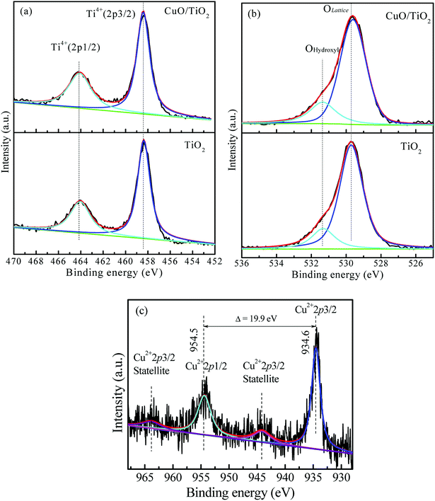 |
| | Fig. 2 XPS spectra of (a) Ti2p and (b) O1s for CuO/TiO2 and TiO2 catalysts. (c) Cu2p for the CuO/TiO2 catalyst. | |
3.3. N2 adsorption–desorption isotherm analysis
The N2 adsorption–desorption isotherms of the CuO/TiO2 composite and TiO2 catalysts prepared at 500 °C are shown in Fig. 3a. The results show hysteresis loops and the type IV adsorption–desorption isotherm. It is known that a hysteresis loop indicates the presence of mesoporous structure in the catalyst.48 Fig. 3b displays the pore size distribution curve. A pore diameter of 1–11 nm and a total pore volume of 0.135 cm3 g−1 were obtained for the CuO/TiO2 prepared with the Eichhornia crassipes template. However, 1–30 nm pore diameter and 0.0159 cm3 g−1 total pore volume were obtained for the TiO2 prepared without template. Furthermore, the specific surface areas of the samples were calculated according to the BET equation and are shown in Table 1. The SBET for CuO/TiO2 was 109 m2 g−1, which was higher than that of 43.8 m2 g−1 for TiO2. This indicates that the utilization of the Eichhornia crassipes template was advantageous for narrowing pore size distribution and increasing pore volume and specific surface area. This may be due to the decomposition of the Eichhornia crassipes template at high temperature and attributed to the formation of a porous networked structure in the TiO2 particles.
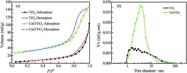 |
| | Fig. 3 (a) Nitrogen adsorption–desorption isotherms and (b) pore size distribution curves of CuO/TiO2 and TiO2. | |
3.4. SEM and TEM analysis
The SEM and TEM images of TiO2 and CuO/TiO2 are shown in Fig. 4a–e. As we see from the SEM (Fig. 4a) and TEM (Fig. 4c) images, the TiO2 prepared without template contained larger aggregated particles. However, the CuO/TiO2 composite catalyst prepared in the presence of Eichhornia crassipes template had smaller aggregates with a particle size of 30–100 nm (Fig. 4b). In the TEM image (Fig. 4d), we observe several pores measuring 2–10 nm and well distributed CuO/TiO2 particles. However, there was no porosity in the TiO2 particle prepared without Eichhornia crassipes (Fig. 4b). It is known that the presence of many uniform nanopores is advantageous because it enhances the surface permeability and improves its adsorption performance. It also enables the rapid transfer of light-excited carriers to the particle surface, to effectively reduce the carrier recombination rate and accelerate photocatalytic reactions.49 Fig. 4e shows the HR-TEM image of CuO/TiO2. The d-spacing value of TiO2 was 3.52 Å for the (101) plane, and the d-spacing value of CuO was 2.540 Å for the (002) plane. These results further confirm the presence of CuO and TiO2 particles in the composite catalyst.
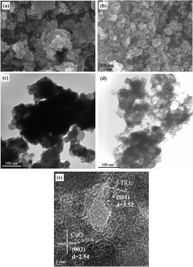 |
| | Fig. 4 SEM images of (a) TiO2 and (b) CuO/TiO2, TEM images of (c) TiO2 and (d) CuO/TiO2, and HR-TEM image (e) of CuO/TiO2 catalyst. | |
3.5. UV-Vis diffuse reflectance spectrum analysis
The UV-Vis diffuse reflectance spectrum (DRS) spectra of the CuO/TiO2, TiO2-Tep and TiO2 catalysts are shown in Fig. 5. It can be seen that the copper-free Eichhornia crassipes template had no effect on the absorption threshold of TiO2, and the light in the ultraviolet and visible light regions. However, CuO/TiO2 synthesized with Cu-enriched Eichhornia crassipes template significantly increased the absorption in the visible region, owing to the absorption of light by CuO nanoparticles. But, the TiO2 had no influence in the ultraviolet light region and on the light absorption threshold of the lattice structure. It is suggested that the combination of n-type semiconductor with p-type semiconductor creates an internal electric field and causes the formation of a p–n heterojunction. The formation of this p–n heterojunction and the band alignment between CuO and TiO2 also greatly facilitate the electron–hole separation and enhance the catalytic activity.32,50
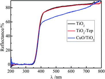 |
| | Fig. 5 Diffuse reflectance spectra of CuO/TiO2, TiO2-Tep, and TiO2 catalysts. | |
3.6. Photocatalytic activity
Fig. 6a shows the catalytic activities of the CuO/TiO2, TiO2-Tep, TiO2, and P25-TiO2 under UV light irradiation. It was observed that the catalytic activity of the CuO/TiO2 was significantly higher than those of the TiO2-Tep, TiO2, and P25-TiO2. Phenol was completely removed by CuO/TiO2 in 80 min. However, phenol removal by TiO2-Tep, TiO2, and P25-TiO2 reached 100%, 82.6%, and 91.4%, respectively, in 140 min. Based on the kinetic analysis, the phenol photocatalytic degradation reaction was also well fitted with pseudo-first-order kinetics. The first-order reaction rate constant (k) sequence was CuO/TiO2 (k = 0.1405 min−1) > TiO2-Tep (k = 0.06942 min−1) > P25-TiO2 (k = 0.06756 min−1) > TiO2 (k = 0.03232 min−1). Fig. 6b shows the activities of the different catalysts under visible light. It is obvious that CuO/TiO2 completely removed phenol in 120 min, but only 19.6%, 8.1%, and 11.3% was removed by TiO2-Tep, TiO2, and P25-TiO2, respectively. In order to test the CuO/TiO2 capability and reusability, the CuO/TiO2 catalyst was continuously tested for six runs under visible light, with the results shown in Fig. 6c. The CuO/TiO2 composite catalyst proved to be stable, retaining good degradation activity for removal of phenol of about 92.5% on the 6th run.
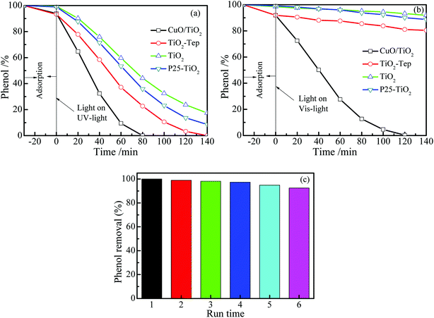 |
| | Fig. 6 Phenol photocatalytic degradation over CuO/TiO2, TiO2-Tep, TiO2, and P25-TiO2 under (a) UV and (b) visible light. (c) The reusability of CuO/TiO2 for phenol degradation under visible light. | |
The improvement of catalytic efficiency of the CuO/TiO2 could be due to the combination of p-type CuO and n-type TiO2 semiconductors. When p-type and n-type semiconductors combine together, a p–n heterojunction is formed. Owing to the presence of carrier concentration gradients, photogenerated holes diffuse from p-type to n-type region and electrons diffuse from n-type to p-type region. At equilibrium, an electric field is created at the junction.51,52 During photocatalysis, the photogenerated electrons can move to the conduction band of the n-type TiO2 and holes can move to the valence band of the p-type CuO. The p–n CuO/TiO2 heterojunction formation facilitates the separation of photogenerated electrons and holes and improves the photocatalytic activities of the materials.29 For this reason, the CuO/TiO2 catalyst had higher photocatalytic activity than TiO2-Tep, TiO2, and P25-TiO2.
3.7. Mechanism for Eichhornia crassipes template synthesis of TiO2
The aquatic plant Eichhornia crassipes has a natural three-dimensional network structure with many hydroxyl groups. The following mechanism is proposed for the synthesis of TiO2 with Eichhornia crassipes template. When the TiCl4 is added into the Eichhornia crassipes suspension, hydrolyzed products of Ti(OH)4−nn+ are obtained (equn (1)).40 Then, the Ti(OH)4−nn+ rapidly disperses through the mesh in Eichhornia crassipes and attaches to the mesh wall (Fig. 7). Ti(OH)4−nn+ interacts with the hydroxy group on the surface of the template and further hydrolyzes to form the nucleation OnTi–(O-template)4−n (eqn (2)). After addition of NH3·H2O, template-TiO2 (eqn (3)) is formed. During the reaction process, the growth of TiO2 is blocked by the three-dimensional network structure of Eichhornia crassipes, the hydroxyl group of the Eichhornia crassipes combines with the hydroxy group of TiO2 (Fig. 7), and crystalline growth and grain agglomeration of the TiO2 precursor are inhibited.40,42 Finally, the template is removed by calcination, leaving CuO/TiO2.| |
 | (1) |
| |
 | (2) |
| |
 | (3) |
 |
| | Fig. 7 The proposed mechanism for the synthesis of TiO2 with Eichhornia crassipes template. | |
4. Conclusions
A CuO/TiO2 composite photocatalyst was prepared by a facile hydrolysis method using the aquatic plant Eichhornia crassipes as a template. The CuO/TiO2 catalyst had excellent catalytic activity for the removal of phenol under UV and visible light irradiation. Phenol was completely removed by CuO/TiO2 in 80 min and 120 min under UV and visible light sources, respectively. The CuO/TiO2 synthesized with the Eichhornia crassipes template was effective for degradation of phenol. The catalytic efficiency of the CuO/TiO2 catalyst may be due to the porosity of the material, which is governed by the three-dimensional network structure and the hydroxyl functional group of the Eichhornia crassipes in the synthetic process. The Eichhornia crassipes also prevents the crystal growth and aggregation and enhances the catalytic activity. Moreover, the formation of a p–n CuO/TiO2 heterojunction facilitates the separation of photogenerated electrons and holes and improves the photocatalytic activity of the material.
Conflicts of interest
There are no conflicts to declare.
Acknowledgements
This work was supported by the National Natural Science Foundation of China under the Grant No. 31000269, China Postdoctoral Program under the grant No. 2018M632562, and Strait Postdoctoral Program under the grant No. 1323H0005.
References
- M. Wang, L. Sun, Z. Lin, J. Cai, K. Xie and C. Lin, Energy Environ. Sci., 2013, 6, 1211 RSC.
- X. Hu, Q. Zhu, X. Wang, N. Kawazoe and Y. Yang, J. Mater. Chem. A, 2015, 3, 17858–17865 RSC.
- Y.-T. Liao, C.-W. Huang, C.-H. Liao, J. C. S. Wu and K. C. W. Wu, Appl. Energy, 2012, 100, 75–80 CrossRef CAS.
- Z. Zhang, X. Jiang, B. Liu, L. Guo, N. Lu, L. Wang, J. Huang, K. Liu and B. Dong, Adv. Mater., 2018, 30, 1705221 CrossRef PubMed.
- Z. Zhang, Y. Liu, Y. Fang, B. Cao, J. Huang, K. Liu and B. Dong, Adv. Sci., 2018, 5, 1800748 CrossRef PubMed.
- N. Lu, Z. Zhang, Y. Wang, B. Liu, L. Guo, L. Wang, J. Huang, K. Liu and B. Dong, Appl. Catal., B, 2018, 233, 19–25 CrossRef CAS.
- Z. Zhang, J. Huang, Y. Fang, M. Zhang, K. Liu and B. Dong, Adv. Mater., 2017, 29, 1606688 CrossRef PubMed.
- B. Khezri, A. C. Fisher and M. Pumera, J. Mater. Chem. A, 2017, 5, 8230–8246 RSC.
- W.-c. Peng, X. Wang and X.-y. Li, Nanoscale, 2014, 6, 8311 RSC.
- H.-W. Chen, C.-Y. Hong, C.-W. Kung, C.-Y. Mou, K. C. W. Wu and K.-C. Ho, J. Power Sources, 2015, 288, 221–228 CrossRef CAS.
- B. Lai, Y. Zhang, Z. Chen, P. Yang, Y. Zhou and J. Wang, Appl. Catal., B, 2014, 144, 816–830 CrossRef CAS.
- H. M. Saleh, T. A. Bayoumi, H. H. Mahmoud and R. F. Aglan, Nucl. Eng. Des., 2017, 315, 194–199 CrossRef CAS.
- P. J. C. Favas, J. Pratas and M. N. V. Prasad, Sci. Total Environ., 2012, 433, 390–397 CrossRef CAS PubMed.
- C. Yu, Z. Wu, R. Liu, D. D. Dionysiou, K. Yang, C. Wang and H. Liu, Appl. Catal., B, 2017, 209, 1–11 CrossRef CAS.
- H. He, B. Huang, G. Fu, Y. Du, D. Xiong, C. Lai and X. Pan, J. Hazard. Mater., 2017, 340, 120–129 CrossRef CAS PubMed.
- I. Zinicovscaia, in Cyanobacteria for Bioremediation of Wastewaters, ed. I. Zinicovscaia and L. Cepoi, Springer International Publishing, Cham, 2016, pp. 17–25, DOI:10.1007/978-3-319-26751-7_3.
- C. A. Martínez-Huitle and E. Brillas, Appl. Catal., B, 2009, 87, 105–145 CrossRef.
- D. P. Zagklis, P. G. Koutsoukos and C. A. Paraskeva, Ind. Eng. Chem. Res., 2012, 51, 15456–15462 CrossRef CAS.
- A. Ajmal, I. Majeed, R. N. Malik, M. Iqbal, M. A. Nadeem, I. Hussain, S. Yousaf, G. Zeshan, G. Mustafa, M. I. Zafar and M. A. Nadeem, J. Environ. Chem. Eng., 2016, 4, 2138–2146 CrossRef CAS.
- J. E. Chen, H.-Y. Lian, S. Dutta, S. M. Alshehri, Y. Yamauchi, M. T. Nguyen, T. Yonezawa and K. C. W. Wu, Phys. Chem. Chem. Phys., 2015, 17, 27653–27657 RSC.
- Z. Zhang, J. Huang, M. Zhang, Q. Yuan and B. Dong, Appl. Catal., B, 2015, 163, 298–305 CrossRef CAS.
- X. Xu, X. Fang, T. Zhai, H. Zeng, B. Liu, X. Hu, Y. Bando and D. Golberg, Small, 2011, 7, 445–449 CrossRef CAS PubMed.
- O. A. Zelekew, D.-H. Kuo, J. M. Yassin, K. E. Ahmed and H. Abdullah, Appl. Surf. Sci., 2017, 410, 454–463 CrossRef CAS.
- S. Naraginti, F. B. Stephen, A. Radhakrishnan and A. Sivakumar, Spectrochim. Acta, Part A, 2015, 135, 814–819 CrossRef CAS PubMed.
- N. Wei, H. Cui, Q. Song, L. Zhang, X. Song, K. Wang, Y. Zhang, J. Li, J. Wen and J. Tian, Appl. Catal., B, 2016, 198, 83–90 CrossRef CAS.
- B. Jiang, L. Jiang, X. Shi, W. Wang, G. Li, F. Zhu and D. Zhang, J. Sol-Gel Sci. Technol., 2014, 73, 314–321 CrossRef.
- M. Daous, V. Iliev and L. Petrov, J. Mol. Catal. A: Chem., 2014, 392, 194–201 CrossRef CAS.
- Y. Yu, Y. Tang, J. Yuan, Q. Wu, W. Zheng and Y. Cao, J. Phys. Chem. C, 2014, 118, 13545–13551 CrossRef CAS.
- J. Bandara, C. P. K. Udawatta and C. S. K. Rajapakse, Photochem. Photobiol. Sci., 2005, 4, 857–861 RSC.
- E. Ovodok, H. Maltanava, S. Poznyak, M. Ivanovskaya, A. Kudlash, N. Scharnagl and J. Tedim, Mater. Today Proc., 2017, 4, 11526–11533 CrossRef.
- X. Yang, H. Fu, A. Yu and X. Jiang, J. Colloid Interface Sci., 2012, 387, 74–83 CrossRef CAS PubMed.
- Y.-T. Liao, Y.-Y. Huang, H. M. Chen, K. Komaguchi, C.-H. Hou, J. Henzie, Y. Yamauchi, Y. Ide and K. C. W. Wu, ACS Appl. Mater. Interfaces, 2017, 9, 42425–42429 CrossRef CAS PubMed.
- J. L. Vivero-Escoto, Y.-D. Chiang, K. Wu and Y. Yamauchi, Sci. Technol. Adv. Mater., 2012, 13, 013003 CrossRef PubMed.
- J. C. Colmenares, R. S. Varma and P. Lisowski, Green Chem., 2016, 18, 5736–5750 RSC.
- M. A. Mohamed, W. N. W. Salleh, J. Jaafar, Z. A. Mohd Hir, M. S. Rosmi, M. A. Mutalib, A. F. Ismail and M. Tanemura, Carbohydr. Polym., 2016, 146, 166–173 CrossRef CAS PubMed.
- B. A. Marinho, R. O. Cristóvão, R. Djellabi, J. M. Loureiro, R. A. R. Boaventura and V. J. P. Vilar, Appl. Catal., B, 2017, 203, 18–30 CrossRef CAS.
- S. Rezania, S. M. Taib, M. F. Md Din, F. A. Dahalan and H. Kamyab, J. Hazard. Mater., 2016, 318, 587–599 CrossRef CAS PubMed.
- B. Lu, Z. Xu, J. Li and X. Chai, Ecol. Eng., 2018, 110, 18–26 CrossRef.
- I. Panfili, M. L. Bartucca, E. Ballerini and D. Del Buono, Sci. Total Environ., 2017, 601–602, 1263–1270 CrossRef CAS PubMed.
- X. Chen, D.-H. Kuo, D. Lu, Y. Hou and Y.-R. Kuo, Microporous Mesoporous Mater., 2016, 223, 145–151 CrossRef CAS.
- X. Chen, D.-H. Kuo and D. Lu, Chem. Eng. J., 2016, 295, 192–200 CrossRef CAS.
- Y. Zhou, E.-Y. Ding and W.-D. Li, Mater. Lett., 2007, 61, 5050–5052 CrossRef CAS.
- S. Miao, Z. Miao, Z. Liu, B. Han, H. Zhang and J. Zhang, Microporous Mesoporous Mater., 2006, 95, 26–30 CrossRef CAS.
- X. Li, T. Fan, H. Zhou, S.-K. Chow, W. Zhang, D. Zhang, Q. Guo and H. Ogawa, Adv. Funct. Mater., 2009, 19, 45–56 CrossRef CAS.
- X. Shari Li, G. E. Fryxell, C. Wang and J. Young, Inorg. Chem. Commun., 2006, 9, 7–9 CrossRef.
- X. Chen and D.-H. Kuo, ACS Sustainable Chem. Eng., 2017, 5, 4133–4143 CrossRef CAS.
- X. Chen, D.-H. Kuo, A. D. Saragih, Z.-Y. Wu, H. Abdullah and J. Lin, Chem. Eng. Sci., 2019, 194, 105–115 CrossRef CAS.
- L. S. G. Y. N. Z. C. Mingqing, Chin. J. Mater. Res., 2010, 24, 610–614 Search PubMed.
- X. Chen and S. S. Mao, Chem. Rev., 2007, 107, 2891–2959 CrossRef CAS PubMed.
- J. Low, B. Cheng and J. Yu, Appl. Surf. Sci., 2017, 392, 658–686 CrossRef CAS.
- S. Ma, J. Xue, Y. Zhou and Z. Zhang, J. Mater. Chem. A, 2014, 2, 7272–7280 RSC.
- O. Ahmed Zelekew and D.-H. Kuo, Phys. Chem. Chem. Phys., 2016, 18, 4405–4414 RSC.
|
| This journal is © The Royal Society of Chemistry 2019 |
Click here to see how this site uses Cookies. View our privacy policy here.  Open Access Article
 b,
Angaw Kelemework Abay
 c,
Qitang Huanga,
Xiaoyun Chen
 *d and
Yushan Zheng*a


