 Open Access Article
Preparation of a porous graphite felt electrode for advance vanadium redox flow batteries†
Lei Zhang‡
ab,
Junpei Yue‡d,
Qi Deng b,
Wei Lingb,
Chun-Jiao Zhoub,
Xian-Xiang Zengb,
Congshan Zhou
 *a,
Xiong-Wei Wu*b and
YuPing Wu
 *bc
*bc
aCollege of Chemistry and Chemical Engineering, Hunan Institute of Science and Technology, Yueyang, Hunan 414006, China. E-mail: zhoucongsh@126.com
bSchool of Chemistry and Materials Science, Hunan Agricultural University, Changsha, Hunan 410128, China. E-mail: wxwcsu05@aliyun.com
cCollege of Energy and Institute for Advanced Materials, Nanjing Tech University, Nanjing, Jiangsu 211816, China. E-mail: wuyp@fudan.edu.cn
dCAS Key Laboratory of Molecular Nanostructure and Nanotechnology, Institute of Chemistry, Chinese Academy ofSciences (CAS), Beijing 100190, China. E-mail: jpyue@iccas.ac.cn
First published on 1st April 2020
Abstract
Rapid mass transfer and great electrochemical activity have become the critical points for designing electrodes in vanadium redox flow batteries (VRFBs). In this research, we show a porous graphite felt (GF@P) electrode to improve the electrochemical properties of VRFBs. The generation of pores on graphite felt electrodes is based on etching effects of iron to carbon. The voltage and energy efficiencies of VRFB based on the GF@P electrode can reach 72.6% and 70.7% at a current density of 200 mA cm−2, respectively, which are 8.3% and 7.9% better than that of untreated GF@U (graphite felt). Further, the VRFBs based on GF@P electrodes possess supreme stability after over 500 charge–discharge cycles at 200 mA cm−2. The high-efficiency approach reported in this study offers a new strategy for designing high-performance electrode materials applied in VRFBs.
1. Introduction
Exploiting large-scale energy storage technologies to accomplish highly-efficient utilization of renewable energy sources is becoming one of the hottest study fields.1,2 Among them, vanadium redox flow batteries (VRFBs) possess many advantages including flexible capacity design, long cycle lifetime and environmental friendliness. Hence, they are considered as the most promising large-scale energy storage system, e.g. they have been equipped with a megawatt–hour-scale.In spite of such great success, its low energy efficiency cannot compete with other electrochemical energy storage technologies, for instance lithium ion batteries, and finding approaches to enhance it is essentially important in the field. The electrodes, which offer sites for the vanadium-ion redox reactions, are regarded as the key for the high-efficiency VRFB. At present, the graphite felts are widely applied as electrode materials for VRFBs owing to their great stability and high conductivity under concentrated acidic conditions.3 Their low catalytic activity and low specific surface area cannot facilitate and promote the redox process. Thus, various electrocatalysts are utilized to modify GF to enhance the redox process. For instance, some metal or metal oxides, such as Ir, Pt, Mn3O4, ZrO2, etc., were deposited on the surface of electrodes as catalysts and they can significantly promote the redox process.4–7 However, precious metals are expensive and prone to promote hydrogen evolution; furthermore, the preparation process is tedious and complicated, limiting their further development. Recently, carbon-based electrocatalysts attracted more and more attentions. Compared with metal-modified GF materials, carbon-based materials are inexpensive and possess good stability under acidic conditions.8 Moreover, most carbon-based catalyst materials have good electronic conductivity and high specific surface area, such as carbon nanotubes,9 graphene oxides,10 porous carbon,11 and other categories.12 Heteroatom doped carbon materials can promote the catalytic activity towards vanadium redox couples by offering the effective active surface sites and electron affinity.13
Additionally, maintaining the stability of the VFRB is another challenge due to the unavoidable decrease in catalytic activity or even mass loss of catalysts. From this standing view, modifying GF themselves to enable them with good catalytic activity is more reliable than decorating them with catalysts. Recently, the porous GF-based materials produced via thermal or KOH etching have been reported in lithium-ion batteries,14 supercapacitors,15 and VRFB.16
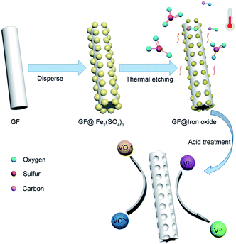
Herein, we present a simple and economical approach to prepare porous graphite felt (GF@P) for VRFB (illustrated in Fig. 1). The porous morphology of GF@P offers it a great surface area and further active sites for the electrochemical reaction of vanadium redox coupling. The porous structure can reduce the electrochemical polarization due to fast mass transportation. Beneficial from this structure, the electrode shows enhanced electrochemical activity and reversibility in redox reactions along with stability at high current densities.
2. Results and discussion
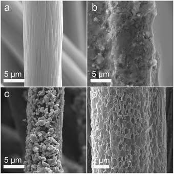
In the process of scientific research, carbon is widely used as a reductant to extract metal from metal oxide ore. The related reaction is called carbon-thermal reduction. In this study, we used the carbon-thermal reduction to construct the proposed porous network-based GF@P electrode. The preparation process of the GF@P fiber electrode is shown in Fig. 1. The whole process can be expressed as follows:11,17 (i) firstly, the thin layer of iron species precursors was coated onto the graphite felt surfaces; (ii) at the high temperature process, the precursors were transferred to iron oxides and subsequently such iron oxides went through carbon-thermal reduction and were reduced to iron species with low valences (this process consumes carbon species on graphite felt); (iii) finally, the iron species were removed with hydrochloric acid to left porous GF.In order to confirm such process, the intermediate products were monitored and examined through SEM images and XRD (Fig. S4†) patterns. Their SEM images of the GF@U, GF@B, GF@A and GF@P are shown in Fig. 2. For the untreated graphite felts, their surface is smooth and clean, while it can be clearly observed that the surface is coated with iron species for GF@B (Fig. 2a and b). From EDS mapping (Fig. S1†), Fe, C, S, O can be found and the XRD pattern indicates the amorphous phase. It can be deduced that the iron species precursors partially hydrolyze to form amorphous phases. After heat treatment, the GF surfaces are covered by numerous small nanoparticles and EDS mapping shows the existence of only Fe, O, and C (Fig. S2†). Meanwhile, XRD pattern indicates the Fe3O4 phase. The existence of Fe2+ in Fe3O4 demonstrate the occurrence of carbon-thermal reduction. After removing iron species on the surface of GF by washing with HCl, numerous pores are generated as expected (Fig. S3† and 2d). All these results perfectly confirm the abovementioned principle.
Raman spectroscopy is of great importance to examine the microstructure of carbon materials and the results are shown in Fig. 3a. Two vibration bands of carbon located at 1350 and 1600 cm−1, which are attributed to D and G peaks. The intensity ratio of D and G peaks (ID/IG) can reflect the defect degree carbon materials. Compared with untreated GF, the abovementioned processes not only create porous on their surface but also increase defects, which can be confirmed from the increased ID/IG ratio (from 1.01 to 1.12). These defects can provide the abundant active sites for redox process (VO2+/VO2+ and V3+/V2+). In order to further understand the atomic environments of carbon, XPS measurements were carried out on these two materials, as shown in Fig. 3. Aside from C, O, and N, the signal of S2p can be found in GF@P, as marked in Fig. 3b. The sulfur can be derived from the iron precursors species. Interestingly, the contents of O and N in GF@P get less than the pristine GF@U, which may be caused by the thermal reduction at high temperature as well. The chemical environments and chemical bonding of these atoms are analyzed via their core level XPS. In order to calibrate the charge effects, the binding energy of C–C bonds was shifted to 284.8 eV. C1s bands can be deconvoluted into three peaks: 284.8 (C1), 285.9 (C2), and 289.8 (C3) eV, which can be contributed to C–C/C–H, C![[double bond, length as m-dash]](https://www.rsc.org/images/entities/char_e001.gif) N/C–N, and O–C
N/C–N, and O–C![[double bond, length as m-dash]](https://www.rsc.org/images/entities/char_e001.gif) O, respectively. It can be clearly seen that the contents of C
O, respectively. It can be clearly seen that the contents of C![[double bond, length as m-dash]](https://www.rsc.org/images/entities/char_e001.gif) O/C–N and O
O/C–N and O![[double bond, length as m-dash]](https://www.rsc.org/images/entities/char_e001.gif) C–O get less for GF@P, in good agreement with the XPS survey results.18,19 The O 1s peak Fig. 3d was divided into two peaks, mainly from C–OH (O2, 533.3 eV) and C
C–O get less for GF@P, in good agreement with the XPS survey results.18,19 The O 1s peak Fig. 3d was divided into two peaks, mainly from C–OH (O2, 533.3 eV) and C![[double bond, length as m-dash]](https://www.rsc.org/images/entities/char_e001.gif) O or O
O or O![[double bond, length as m-dash]](https://www.rsc.org/images/entities/char_e001.gif) C–N (O1, 531.8 eV) groups.20 It can be seen from Fig. 3e that nitrogen elements can be composed of four characteristic peaks, N4 (401.9), N3 (401.1 eV), N2 (399.8 eV), and N1 (398.3 eV), which can be attributed to oxygenated-N, graphitic-N, pyrrolic-N, and pyridinic-N,respectively.21 Simultaneously, the high-resolution S2p spectra (Fig. 3f) exhibited three main peaks at 167.8 (S3), 165.1 (S2), and 163.9 (S1) eV, which can be assigned to –C–SOx, –C–SOy, C–S, respectively.22 Sulfur doping is conducive to mutual conversion between V2+/V3+ and VO2+/VO2+.23 The porous morphology of the electrode surface promotes vanadium ion diffusion, and then the C–OH, pyridinic N and pyrrolic N on the electrode surface provide active sites for vanadium redox reaction. Finally, the sulfur element can form S–O–V transition state with the vanadium and accelerate the vanadium ion conversion. So these factors together improve the performance of the battery.10,12,22
C–N (O1, 531.8 eV) groups.20 It can be seen from Fig. 3e that nitrogen elements can be composed of four characteristic peaks, N4 (401.9), N3 (401.1 eV), N2 (399.8 eV), and N1 (398.3 eV), which can be attributed to oxygenated-N, graphitic-N, pyrrolic-N, and pyridinic-N,respectively.21 Simultaneously, the high-resolution S2p spectra (Fig. 3f) exhibited three main peaks at 167.8 (S3), 165.1 (S2), and 163.9 (S1) eV, which can be assigned to –C–SOx, –C–SOy, C–S, respectively.22 Sulfur doping is conducive to mutual conversion between V2+/V3+ and VO2+/VO2+.23 The porous morphology of the electrode surface promotes vanadium ion diffusion, and then the C–OH, pyridinic N and pyrrolic N on the electrode surface provide active sites for vanadium redox reaction. Finally, the sulfur element can form S–O–V transition state with the vanadium and accelerate the vanadium ion conversion. So these factors together improve the performance of the battery.10,12,22
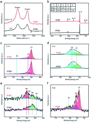 | ||
| Fig. 3 (a) Raman spectra of GF@U and GF@P of electrode materials. (b) XPS spectra of GF@U and GF@P. (c–f) High-resolution of C1s, O1s, N1s and S2p for GF@U and GF@P. | ||
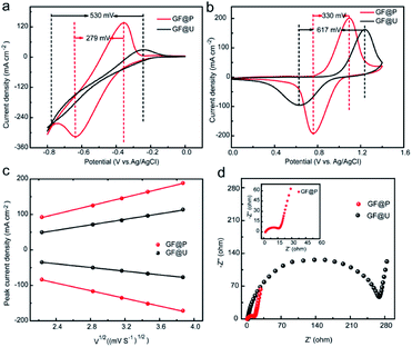
The effects of such treatment on electrochemical performance of GF electrodes for VRFB were examined using cyclic voltammetry in a three-electrode system, shown in Fig. 4a and b. It can be clearly observed that the anodic and cathodic peak potential difference (ΔE) for V3+/V2+ and VO2+/VO2+ using GF@P are 279 and 330 mV, respectively. These values are significantly less than the ones using GF@U electrode. The related parameters are listed in Table S1.† The decrease in potential separation demonstrates the small polarization for redox process and the fast kinetic process. The fast kinetic process of redox couples on GF@P electrodes may be originated from the high surface area and high electrocatalytic activity from heteroatom doping, as shown in SEM and XPS spectra. In addition, for the redox couple of V3+/V2+ the one using GF@U electrode showed no obvious redox peak when compared with the one using GF@P electrode, which may be due to the relatively weak catalysis of GF@U electrode to V2+/V3+ ion conversion and the occurrence of hydrogen evolution reaction. All these results confirm, GF@P electrodes present excellent catalytic activity for both V2+/V3+ and VO2+/VO2+ redox couples.
In order to understand the detailed kinetic process, scanning rate dependent CVs are carried out and shown in Fig. S5.† The ratio of −Ipc/Ipa for the VO2+/VO2+ redox reaction using GF@U and GF@P electrodes at different sweep rates are shown in Fig. S6.† Compared with the blank GF (0.706), the value for GF@P (0.932) is close to 1, indicating the high reversibility. Moreover, the sweep rate does not change the ratio too much for GF@P, indicating the much improved kinetic process. Furthermore, the good linear relationship between ip and the square root of the scanning rates (ν1/2) (Fig. 4c) shows that the diffusion process controls the electrochemical reaction of the VO2+/VO2+ couple. For the electrochemically reversible process, Randles Sevcik equation can be used to estimate the diffusion coefficient.24
| ip = 2.99 × 10⁵α1/2An3/2D01/2ν1/2C0. | (1) |
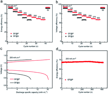
Furthermore, the flow batteries based GF@P electrodes were assembled and evaluated, as shown in Fig. 5. The charge and discharge curves of VRFBs using GF@U and GF@P electrodes at the current density of 200 mA cm−2 (Fig. 5c) confirmed the small potential polarization when using GF@P electrodes again. In addition, it can be clearly seen from Fig. S7† that GF@P battery shows a lower charging and discharging overpotential and has a higher charging and discharging capacity. This small polarization can stand for the application of high current density, e.g. more than 300 mA cm−2 when using GF@P while this value is only 225 mA cm−2 for GF@U. Furthermore, the voltage and energy efficiencies of the battery using GF@P electrode at 200 mA cm−2 are 72.6% and 70.7%, respectively, each of which increases by 8.3% and 7.9% compared with GF@U. The cycling stability was evaluated as well and the energy efficiency at 200 mA cm−2 of VRFBs using GF@P electrodes maintain very stable after 500 cycles. These excellent electrochemical performances confirm the success of porous electrode design, which works as good electrocatalytic activity, promotes mass diffusion, increase the cycling lifetime.
3. Experiment
3.1 Preparation of GF@P
Firstly, GF (3 × 4 cm2) was immersed in 50 mL 1.6 mol L−1 ferric sulfate solution. The resulted samples were then dried at 60 °C for 12 hours. Next, the modified GF was annealed in N2 atmosphere at 900 °C for 3 h with a heating rate of 5 °C min−1. Finally, the activated GF was soaked in concentrated hydrochloric acid to dissolve oxides and obtain porous graphite felt. The resulted GF was referred to as GF@P and untreated GF was referred to as GF@U. In order to better observe the changes of graphite felt in the reaction process, the graphite felts before and after the heat treatment were named GF@B and GF@A, respectively. All samples were repeatedly rinsed with deionized water before testing.3.2 Characterization
The morphology of the sample was observed by field emission scanning electron microscope (Tescan Mira3) under 15 kV and graphitisation degree and defects of the electrode materials were studied by Raman spectroscopy (LabRAM HR Evolution) using 532 nm laser excitation. The Elemental composition of the electrode materials was determined using X-ray photoelectron spectroscopy (XPS) using an EscaLab 250Xi equipped with a 200 W Al-Kα radiation source. The crystallinity of samples was detected by XRD in the condition of Cu Kα radiation (40 kV, 40 mA, 10° min−1 from 10 to 80°).3.3 Electrochemical measurement
The electrochemical properties of the three-electrode systems were tested using Ag/AgCl as a reference electrode, platinum network as the counter electrode, and graphite felt (0.5 × 0.5 cm−2) as the working electrode. Cyclic voltammetry was tested in the range of −0.8–1.4 V with different scanning rates the CHI604E electrochemical workstation. Electrochemical impedance spectra measurements were carried out with a voltage amplitude of 5 mV and a frequency scope of 0.01 Hz to 100 kHz. An aqueous solution with 0.1 M VOSO4 and 3 M H2SO4 was used as the electrolyte for these measurements. For VRFB, the vanadium battery Nafion 115 membrane was used as an ion-exchange membrane and the size of graphite felt electrode used is 2 × 2 cm2. 15 mL electrolytes composed of 1.5 M V3+, 1.5 M VOSO4, 3 M H2SO4 solution was circulated though the electrodes with the flow velocity of 40 mL min−1 using a peristaltic pump. The charge–discharge profiles were collected on Land electrochemical systems (Land CT2001A) with cut-off voltage of approximately 0.8–1.65 V, which can prevent the high-voltage corrosion of the graphite plate and electrode.4. Conclusions
In conclusion, we have successfully prepared porous GF electrodes using chemical etching. The formation of uniform pores significantly increased the specific surface area of the electrode, supplying more active sites for the redox reaction of vanadium ions, thus improving its electrochemical activity and kinetic reversibility. The discharge-specific capacity of the VRFB assembled with GF@P electrode was higher than that of the GF@U electrode. Under the high current density of 200 mA cm−2, the VRFB with the GF@P electrode can work for 500 cycles without a significant attenuation, showing excellent rate performance and ultra-long cycle stability. The method employed in this study can be extended to other carbon-based electrodes. It provides a new way to prepare various electrodes and has a broad application prospect in the energy storage and conversion processes.Conflicts of interest
The authors declare no conflict of interest.Acknowledgements
This research was supported by Natural Science Foundation of Hunan Province of (2019JJ50214 and 2019JJ50215), the National Natural Science Foundation Committee of China (Distinguished Youth Scientists Project of 51425301, U1601214, 51573013 and 51772147), the Double First-Class Construction Project of Hunan Agricultural University (Grant no. SYL201802002, SYL201802008).Notes and references
- X. Ke, J. M. Prahl, J. I. D. Alexander, J. S. Wainright, T. A. Zawodzinski and R. F. Savinell, Chem. Soc. Rev., 2018, 47, 8721–8743 RSC
.
- S. Hennessey and P. Farràs, Chem.Commun., 2018, 54, 6662–6680 RSC
.
- P. C. Ghimire, R. Schweiss, G. G. Scherer, N. Wai, T. M. Lim, A. Bhattarai, T. D. Nguyen and Q. Yan, J. Mater. Chem. A, 2018, 6, 6625–6632 RSC
.
- H. Zhou, Y. Shen, J. Xi, X. Qiu and L. Chen, ACS Appl. Mater. Interfaces, 2016, 8, 15369–15378 CrossRef CAS PubMed
.
- C. Flox, J. Rubio-Garcia, R. Nafria, R. Zamani, M. Skoumal, T. Andreu, J. Arbiol, A. Cabot and J. R. Morante, Carbon, 2012, 50, 2372–2374 CrossRef CAS
.
- Z. He, L. Dai, S. Liu, L. Wang and C. Li, Electrochimi. Acta, 2015, 176, 1434–1440 CrossRef CAS
.
- W. H. Wang and X. D. Wang, Electrochimi. Acta, 2007, 52, 6755–6762 CrossRef CAS
.
- Y. Xiang and W. A. Daoud, J. Mater. Chem. A, 2019, 7, 5589–5600 RSC
.
- Y. Chung, C. Noh and Y. Kwon, J. Power Sources, 2019, 438, 227063 CrossRef CAS
.
- Q. Deng, P. Huang, W. X. Zhou, Q. Ma, N. Zhou, H. Xie, W. Ling, C.-J. Zhou, Y. X. Yin, X. W. Wu, X. Y. Lu and Y. G. Guo, Adv. Energy Mater., 2017, 7, 1700461 CrossRef
.
- Y. Liu, Y. Shen, L. Yu, L. Liu, F. Liang, X. Qiu and J. Xi, Nano Energy, 2018, 43, 55–62 CrossRef CAS
.
- Q. Ma, X. X. Zeng, C. Zhou, Q. Deng, P. F. Wang, T. T. Zuo, X. D. Zhang, Y. X. Yin, X. Wu, L. Y. Chai and Y. G. Guo, ACS Appl. Mater. Interfaces, 2018, 10, 22381–22388 CrossRef CAS PubMed
.
- R. Wang and Y. Li, J. Power Sources, 2019, 421, 139–146 CrossRef CAS
.
- M. S. Balogun, W. Qiu, F. Lyu, Y. Luo, H. Meng, J. Li, W. Mai, L. Mai and Y. Tong, Nano Energy, 2016, 26, 446–455 CrossRef CAS
.
- T. Li, W. Zhang, L. Zhi, H. Yu, L. Dang, F. Shi, H. Xu, F. Hu, Z. Liu, Z. Lei and J. Qiu, Nano Energy, 2016, 30, 9–17 CrossRef CAS
.
- T. Liu, X. Li, C. Xu and H. Zhang, ACS Appl. Mater. Interfaces, 2017, 9, 4626–4633 CrossRef CAS PubMed
.
- H. Wu, J. B. Jespersen, F. J. Frandsen, P. Glarborg, M. Aho, K. Paakkinen and R. Taipale, AIChE J., 2013, 59, 4314–4324 CrossRef CAS
.
- P. Han, Y. Yue, Z. Liu, W. Xu, L. Zhang, H. Xu, S. Dong and G. Cui, Energy Environ. Sci., 2011, 4, 4710 RSC
.
- Z. He, Y. Jiang, Y. Wei, C. Zhao, F. Jiang, L. Li, H. Zhou, W. Meng, L. Wang and L. Dai, Electrochimi. Acta, 2018, 259, 122–130 CrossRef CAS
.
- H. Sheng, Q. Ma, J. G. Yu, X. D. Zhang, W. Zhang, Y. X. Yin, X. Wu, X. X. Zeng and Y. G. Guo, ACS Appl. Mater. Interfaces, 2018, 10, 38922–38927 CrossRef CAS PubMed
.
- Y. Gao, H. Wang, Q. Ma, A. Wu, W. Zhang, C. Zhang, Z. Chen, X. X. Zeng, X. Wu and Y. Wu, Carbon, 2019, 148, 9–15 CrossRef CAS
.
- Y. Xie, Z. Meng, T. Cai and W. Q. Han, ACS Appl. Mater. Interfaces, 2015, 7, 25202–25210 CrossRef CAS PubMed
.
- A. B. Shah, Y. Wu and Y. L. Joo, Electrochimi. Acta, 2019, 297, 905–915 CrossRef CAS
.
- W. Ling, Z. A. Wang, Q. Ma, Q. Deng, J. F. Tang, L. Deng, L. H. Zhu, X. W. Wu, J. P. Yue and Y. G. Guo, Chem. Commun., 2019, 55, 11515–11518 RSC
.
Footnotes |
| † Electronic supplementary information (ESI) available. See DOI: 10.1039/d0ra00666a |
| ‡ The authors equally contributed to this work. |
| This journal is © The Royal Society of Chemistry 2020 |

