 Open Access Article
Creative Commons Attribution 3.0 Unported Licence
Wood modification for the synthesis of MOF@wood composite materials with increased metal–organic framework (MOF) loading†
Alex
Spieß
,
Janis
Wiebe
,
Egor
Iwaschko
,
Dennis
Woschko
 and
Christoph
Janiak
 *
*
Abteilung für nanoporöse und nanoskalierte Materialien, Institut für Anorganische Chemie und Strukturchemie, Heinrich-Heine-Universität Düsseldorf, 40204 Düsseldorf, Germany. E-mail: janiak@uni-duesseldorf.de; Tel: +49 211 81 12286
First published on 13th September 2022
Abstract
For potential applications it is necessary to shape metal–organic frameworks (MOFs) into composite materials. Due to its naturally porous and highly ordered structure, wood is a candidate for the synthesis of MOF-composite materials. Herein, we report two easy wood functionalization methods using maleic anhydride (MA) and (3-aminopropyl)triethoxysilane (APTES) to achieve MOF@wood composites with increased, in situ formed MOF loading compared to unfunctionalized wood. With the carboxylate-donating maleate anchor from MA and the carboxylate MOF MIL-53(Al) or with the amino-donating anchor APTES and the imidazolate MOF ZIF-8 MOF loadings up to 13 wt% could be reached in each case, forming composites with micro–meso–macrohierarchical porosity. The resulting composite materials were tested for water purification, represented by the adsorption of methylene blue, and heterogeneous catalysis, represented by the Knoevenagel condensation between benzaldehyde and malononitrile. Both potential applications were tested under static and continuous conditions, showing promising results for the application of MOF@wood composite materials in flow-through filtration and catalysis.
Design, System, ApplicationThrough the two molecular functionalization agents we could optimize the formation of a carboxylate MOF by using the carboxylate-forming MA and of a nitrogen-linker MOF by using the amino-containing APTES. To the best of our knowledge this strategy is new for MOFs and should be generally applicable to any carboxylate or imidazolate MOF. MOFs are generally investigated for their porosity for gas, vapor or molecule uptake, as heterogeneous catalysts etc. The MOF@wood composites also fulfill these desired functionalities as a formulated or shaped MOF material. The MOF@wood design should be applicable to many more roles for which MOFs are already investigated. The porosity, as the desired systems functionality, was fully preserved in the wood, unlike in MOF@polymer composites. Design constraints can be due to the difference between wood types. The MOF@wood composites may open the way to incorporate MOFs in wood consumer goods for air or water purification, humidity control through the water-uptake and release of the MOF or to deliver fragrances through the slow release from the MOF. The mechanical stability of wood may also increase through the inside MOF skeleton. |
Introduction
Metal–organic frameworks (MOFs) are a class of potentially porous and crystalline coordination networks comprised of inorganic metal nodes which are connected by multitopic organic ligands (linkers).1 Due to the huge variety of possible structures, by modifying metals and linkers, and the resulting design possibilities,2,3 MOFs have found multiple potential applications, such as gas storage and separation,4–6 water and air purification,7,8 catalysis,9–11 heat transformation12,13 and drug delivery.14,15 However, MOFs are usually obtained as microcrystalline powders, which limits their manageability.16,17 For realistic applications, MOFs would have to be shaped into monoliths, films, membranes etc. by being processed as composite materials in a matrix through the addition of polymers, binders etc.18–21 The additive matrix has to be chosen according to the envisioned application. A general prerequisite for any matrix has to be to retain the MOF porosity and access to the MOF pores which is not necessarily guaranteed with organic polymers.22Wood can be a natural material overcoming these problems. It is a hierarchical composite containing intrinsic porosity and great mechanical stability.23–25 Its hierarchical structure is composed of cellulose and hemicelluloses, which form the porous structure, and of lignin, which provides the mechanical stability. A schematic construction of wood is shown in Fig. 1a. An individual wood cell is constructed of a primary and a secondary wall with the lumen, the porous element, in the center. The primary and secondary walls mainly consist of semi-crystalline cellulose-microfibrils which are supported by a variety of hemicelluloses. These cells are connected by the lignin-rich middle lamella, which accounts for the rigidity and mechanical stability of wood.26,27 Lignin itself is a random polymer consisting of the three monomers: coumaryl alcohol, coniferyl alcohol and sinapyl alcohol (Fig. 1b).28 Wood can generally be differentiated into softwood and hardwood (Fig. 1c). Softwoods are usually only comprised of one cell type, which varies in thickness and diameter depending on the life cycle around the seasons, which results in the characteristic growth rings of wood (the so called “latewood” consist of cells with smaller diameter and thicker cell walls resulting in a darker color). Hardwoods contain different cell types resulting in a more complex structure compared to softwood. In both types, the lumina are interconnected by pits and wood rays, which grow radially to the growth direction of the tree. Together this gives the hierarchically porous and oriented anisotropic properties of wood.26,29,30
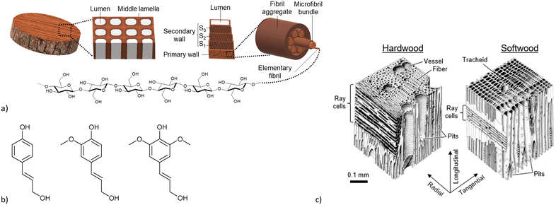 | ||
| Fig. 1 a) Schematic construction of wood, from the bulk via the individual cell to the elemental fibril. b) Lignin monomers, from left to right: coumaryl alcohol, coniferyl alcohol, sinapyl alcohol. c) Structural differences between hard- and softwoods. Reprinted from ref. 30 © 2019 by MDPI. | ||
As a result of these intrinsic properties wood can be a potential host matrix for the synthesis of MOF@wood composite materials with hierarchical micro, meso and macro porosity and directional mass transport.31 Only a few MOF@wood composite materials have been reported so far (Table S2, ESI†). MOFs in wood materials include UiO-66, HKUST-1 and ZIF-8. The resulting composites were characterized by increased mechanical stability compared to natural wood and other MOF@polymer composite materials. When the Cu-MOF HKUST-1 (Cu-BTC) was incorporated increased antibacterial properties compared to natural wood were found. MOF@wood composites were tested for potential applications such as the removal of organic pollutants from water,32–34 solar steam generation for freshwater production by increasing the water evaporation efficiency using solar light35 and iodine capture.36 Furthermore, wood composite materials have been synthesized with metal nanoparticles incorporated into MOF@wood materials which can be used for continuous flow through hydrogen generation.37 However, the reported materials contain only small amounts of MOF. There are also reports of MOF-composite materials using wood-based materials such as wood aerogel and carbonized wood or carbonized MOF@wood materials,38–44 but most of these materials lose mechanical stability after delignification or carbonization. Huang et al. were able to increase the MOF loading without delignification of the wood by deploying the method of localized magnetic induction heating (LMIH), where the wood was first functionalized by Fe2O3 nanoparticles and the MOF synthesis was conducted in a magnetic field. Using this LMIH method, the MOF precursor solution was heated only inside the wood lumina resulting in MOF-loadings up to 50 wt% without destroying the structural integrity of the wood.45
Herein, we present two wood functionalization methods using maleic anhydride (MA) and (3-aminopropyl)triethoxysilane (APTES) to achieve MOF@wood composite materials with increased MOF loadings. Functionalization of cellulosic substrates has been reported before.46,47 Cyclic acid anhydrides like maleic anhydride can be used to functionalize substrates, including wood, with carboxylic acid groups.48–50 APTES is a well-known agent to introduce amino-groups on surfaces like alumina and titania to induce the targeted growth of zeolitic imidazolate frameworks (ZIFs) on the surface of the so functionalized substrates.51,52 Two exemplary MOFs have been used here to examine the effects of the different functionalization methods: MIL-53(Al) with Al-carboxylate bonds and ZIF-8 with Zn–N coordination (see section 5, ESI† for MOF structures). These newly synthesized MOF@wood composite materials are then tested for the adsorption of methylene blue from aqueous solution and as a catalyst for the Knoevenagel reaction between benzaldehyde and malononitrile, which are known potential applications for MIL-53(Al) and ZIF-8, respectively.53,54 These experiments are performed both in static and continuous conditions.
Materials and methods
Pine wood rods with a diameter of 14 mm were cut into disks with a thickness of 3 mm using a band saw. Afterwards, the wood surface was polished using a smoothing plane (Fig. S1, ESI†). All chemicals were obtained from commercial suppliers and used without further purification. A list of all chemicals and suppliers can be found in the ESI† (Table S1).Wood NaOH-pretreatment
Wood was pretreated with NaOH according to the procedure described by Tu et al.32 with minor modifications. Approximately 0.5 g of pine wood disks were added to 50 mL of aqueous NaOH (15% w/v), vacuum impregnated three times by evacuating the flask and venting it to atmospheric pressure with nitrogen and stirred for one hour. Afterwards, the wood was removed and washed with water until the pH = 9 was reached. Then the wood was first dried in air at room temperature for at least 24 h followed by drying at 60 °C under vacuum overnight to minimize shrinking of the wood. The wood pretreated with this method is denoted as Pine-NaOH.Wood functionalization with maleic anhydride (MA)
Wood was functionalized with maleic anhydride according to the method by Montanari et al.50 Freshly dried untreated pine wood (∼1.4 g) was first soaked with acetone (20 mL). Maleic anhydride (∼50 g) was loaded into a flask and melted in an oven at 100 °C. Then, the acetone-soaked wood was added into the molten maleic anhydride and left to react at 100 °C for 24 h with no stirring. Afterwards, the hot wood was directly transferred into acetone and washed extensively with altogether about 250 mL of acetone, dried at room temperature in air for 4 hours and then at 60 °C under vacuum overnight. The wood pretreated with this method is denoted as Pine-MA.Wood functionalization with (3-aminopropyl)triethoxysilane (APTES)
The pine wood disks (∼1.4 g) were first evacuated for one hour in a flask equipped with a septum. The amount of 6 mL (25 mmol) of APTES (threefold molar excess relative to the wood, assuming the wood is only composed of cellulose with a molecular weight of 162 g mol−1 per anhydroglucose unit) was first dissolved in 12 mL of DMSO (about twice the volume relative to APTES) and then added to the flask (still under vacuum) through the septum. The mixture was vented with nitrogen to atmospheric pressure and left to react at 70 °C for 6 hours. Then the wood was removed, quickly rinsed with 10 mL of ethanol and kept at 70 °C overnight. Afterwards, the wood was washed three times with 20 mL of ethanol, dried in air at room temperature for 4 hours and then dried at 60 °C under vacuum overnight. The wood pretreated with this method is denoted as Pine-APTES.MIL-53(Al) and MIL-53(Al)@wood synthesis
MIL-53(Al) was synthesized according to the method described by Mounfield III et al.55 Briefly, 1.3 g (3.5 mmol) of aluminum nitrate nonahydrate and 1.3 g (7.8 mmol) of terephthalic acid were dissolved in 30 mL of dimethylformamide (DMF). The clear solution was transferred into a screwcap bottle and heated at 120 °C for 72 h. The resulting precipitate was centrifuged, washed three times each with 20 mL of DMF and 20 mL of ethanol and dried at 60 °C under vacuum overnight. The procedure to synthesize the MOF@wood composite materials was the same but included a vacuum impregnation of the wood before heating: two wood disks (∼0.5 g) from the same pretreatment (Pine, Pine-NaOH, Pine-MA or Pine-APTES) were first evacuated in a flask equipped with a septum for one hour. Then, the prepared MOF-precursor solution was injected to the flask through the septum while still under vacuum, followed by venting with nitrogen to atmospheric pressure and soaking for one hour. Directly afterwards, the synthesis and workup were conducted as for neat MIL-53(Al).ZIF-8 and ZIF-8@wood synthesis
ZIF-8 was synthesized according to the method described by Tu et al.32 Briefly, 1.6 g (5.4 mmol) of zinc nitrate hexahydrate was dissolved in 2 mL of water and 16.6 mL of methanol, while 8.8 g (107.2 mmol) of 2-methylimidazole were separately dissolved in the same amount of the same solvent mixture. Then, both solutions were combined and stirred at room temperature for 24 h. The resulting precipitate was centrifuged at 10![[thin space (1/6-em)]](https://www.rsc.org/images/entities/char_2009.gif) 000 rpm (max. 10
000 rpm (max. 10![[thin space (1/6-em)]](https://www.rsc.org/images/entities/char_2009.gif) 400 g), washed three times each with 20 mL of water and 20 mL of ethanol, and dried at 60 °C overnight. The procedure to synthesize the MOF@wood composite materials was the same but included a vacuum impregnation of the wood with the zinc nitrate solution: Two pieces of wood (Pine, Pine-NaOH, Pine-MA or Pine-APTES) were first evacuated in a flask equipped with a septum for one hour. Then, the prepared zinc nitrate solution was injected into the flask through the septum while still under vacuum and vented with nitrogen to atmospheric pressure. The wood was first soaked for two hours with the zinc metal salt, before adding the solution of 2-methylimidazole. Directly afterwards, the synthesis and workup were conducted as for neat ZIF-8.
400 g), washed three times each with 20 mL of water and 20 mL of ethanol, and dried at 60 °C overnight. The procedure to synthesize the MOF@wood composite materials was the same but included a vacuum impregnation of the wood with the zinc nitrate solution: Two pieces of wood (Pine, Pine-NaOH, Pine-MA or Pine-APTES) were first evacuated in a flask equipped with a septum for one hour. Then, the prepared zinc nitrate solution was injected into the flask through the septum while still under vacuum and vented with nitrogen to atmospheric pressure. The wood was first soaked for two hours with the zinc metal salt, before adding the solution of 2-methylimidazole. Directly afterwards, the synthesis and workup were conducted as for neat ZIF-8.
Methylene blue (MB) adsorption experiments
The amount of 50–60 mg (a composite disk was broken apart to achieve the targeted amount) of dried wood or MOF@wood composite material or 5–6 mg of dried MOF was shaken in 20 mL of an aqueous MB solution with a concentration of 5 mg L−1. After 48 h the change in concentration of the solution was checked via UV/VIS-spectroscopy (at 664 nm). For kinetic sorption studies 50–60 mg of wood or MOF@wood composite were shaken in 50 mL aqueous MB solution (5 mg L−1) and aliquots of 1 mL were taken after 1, 2, 8, 24, 32 and 48 h. The concentration of MB was followed by UV/VIS-spectroscopy (at 664 nm). For sorption isotherm studies, 50–60 mg of MOF@wood composite material was shaken for 48 h in 20 mL of MB solutions with different concentrations (1, 5, 10, 100, 250 and 500 mg L−1). Afterwards, the change in concentration was determined by UV/VIS-spectroscopy (at 664 nm). For the measurement the solutions were diluted to an approximate concentration of 5 mg L−1 from their initial concentration if necessary. All experiments were performed in duplicate and the similar values were averaged. For continuous filtration experiments, a disk of the MOF@wood composite (diameter = 14 mm, thickness = 3 mm, mass = 234 mg) was first soaked in water overnight and then fixed into a custom-made filtration setup (see below). To this, a syringe filled with 20 mL of methylene blue solution in water (5 mg L−1) was connected and pressed through the composite using a syringe pump at a pumping rate of 0.05 or 0.03 mL min−1. Four fractions were collected, each after 5 mL of solution pressed out of the syringe, and the remaining concentration of methylene blue was determined by UV/VIS-spectroscopy (at 664 nm).Catalytic studies for the Knoevenagel condensation
For catalytic studies, 50–60 mg of dried wood or MOF@wood composite material or 5–6 mg of MOF were added to a solution of benzaldehyde (1 mmol) and malononitrile (1 mmol) in 2 mL of anhydrous toluene. The reaction vessel was then shaken on a VWR Mini Shaker for 48 h at room temperature. After 1, 2, 6, 23, 31, 48 and 72 h aliquots of 10 μL were taken, diluted to 1 mL with toluene and the concentrations were determined using gas chromatography. For catalyst reusability tests, the MOF@wood composite material was washed with toluene and ethanol for at least 24 h and reused again applying the same procedure as before. For the non-catalytic wood, no reusability tests were performed. For continuous catalysis experiments, the same setup was used as for continuous filtration experiments. In this case the MOF@wood composite (diameter = 14 mm, thickness = 3 mm, mass = 338 mg) was first soaked in toluene, before 5 mL of a solution of benzaldehyde and malononitrile in toluene (1 mol L−1 each) were pressed through the composite at a pumping rate of 0.02 or 0.01 mL min−1. Five fractions were collected, each after 1 mL of solution were pressed out of the syringe. From each fraction 10 μL solution were taken and diluted to 1 mL with toluene before being analyzed with gas chromatography.Powder X-ray diffraction (PXRD) patterns were recorded on a Bruker D2 Phaser equipped with a copper X-ray generator (Cu-Kα1λ = 1.5406 Å) at 30 kV and 10 mA. Samples were dusted onto a Si-low background sample holder and measured in the 2θ range of 5–50° at a scan rate of 0.024° s−1. To collect the PXRD patterns of the composite materials, a disk of MOF@wood was fractured and a sample was scratched off of the cross-section.
Nitrogen physisorption isotherms were obtained on a Quantachrome Autosorb-6 at 77 K with nitrogen gas of 99.9990% purity. Prior to the measurement, samples were degassed at 120 °C for at least 3 hours to a pressure of less than 30 mTorr. Brunauer–Emmett–Teller (BET) surface areas were determined at relative pressures p p0−1 between 0.03 and 0.06 for MIL-53(Al) and its composites or between 0.01 and 0.04 for ZIF-8 and its composites. The isotherms were collected on a standard Autosorb-6 device with a pressure transducer accuracy of 0.11% and a maximum vacuum of 5 × 10⁻³ mbar. As a result, the ultra-low-pressure region cannot reliably be measured, causing the isotherms to start above an uptake of 0 cm3 g−1.
Fourier-transform infrared (FT-IR) spectra were recorded on a Bruker FT-IR Tensor 37 spectrometer in the attenuated total reflection (ATR) mode in the range of 4000–550 cm−1.
Scanning electron microscopy (SEM) images and energy dispersive X-ray (EDX) analysis were recorded on a Jeol JSM-6510LV QSEM electron microscope equipped with a LaB6 filament and a Bruker XFlash 410-M EDX detector at an acceleration voltage of 20 kV. Prior to the measurement, samples were coated with gold using a Jeol JFC 1200 sputter coater.
Atomic absorption spectroscopy (AAS) was conducted on a PerkinElmer PinAAcle 900 T with Zn and Al hollow cathode lamps. For zinc, an acetylene–air flame was used for atomization, while for aluminum, a graphite furnace was used. Samples were prepared by digestion of 15–20 mg of MOF@wood composite in aqua regia (4 mL of a 3![[thin space (1/6-em)]](https://www.rsc.org/images/entities/char_2009.gif) :
:![[thin space (1/6-em)]](https://www.rsc.org/images/entities/char_2009.gif) 1 v
1 v![[thin space (1/6-em)]](https://www.rsc.org/images/entities/char_2009.gif) :
:![[thin space (1/6-em)]](https://www.rsc.org/images/entities/char_2009.gif) v mixture of 37% HCl and 65% HNO3) at 120 °C until the solvent evaporated completely, dissolving the residue in 5 mL HNO3 (0.5 mol L−1) and dilution in purified water to appropriate concentrations. The calibrating samples were prepared from commercial aluminum and zinc standard solutions (1000 mg L−1) by dilution to required concentrations.
v mixture of 37% HCl and 65% HNO3) at 120 °C until the solvent evaporated completely, dissolving the residue in 5 mL HNO3 (0.5 mol L−1) and dilution in purified water to appropriate concentrations. The calibrating samples were prepared from commercial aluminum and zinc standard solutions (1000 mg L−1) by dilution to required concentrations.
Mercury intrusion porosimetry (MIP) was performed on a combined Porotec Pascal P140 + P440 device, where the P140 device reaches pressures up to 400 kPa and the P440 device reaches pressures up to 400 MPa, ultimately reaching a determinable pore size from 100 μm down to 4 nm. Both measurements have been combined into one using the SOLID Software Ver 1.6.6 by ThermoFisher Scientific. Pore size and surface characterization was performed using the “cylindrical and plate” model.
UV/Vis spectra were recorded on an Analytik Jena Specord S 600 spectrometer from 190 to 1000 nm in a quartz glass cuvette with a light path length of 10 mm.
Gas chromatography was conducted on a Shimadzu GC-2010 system with a flame ionization detector operated at 350 °C. The used column (type SB-1 by HP) was 30 m long and 0.25 mm in diameter. The column was first heated at 40 °C for 4 min, then heated to 220 °C within 3.5 min and kept at this temperature for a further 5 min. Product yield was determined by calibration using a commercially purchased sample of the benzylidene malononitrile product of the Knoevenagel condensation.
Thermogravimetric analyses (TGA) were performed on a Netzsch Tarsus TG 209 under synthetic air (20.5 ± 0.5% O2 in N2) from room temperature to 1000 °C with a heating rate of 10 °C min−1 in Al2O3-crucibles.
Purified water with a residual conductivity of 0.05 μS cm−1 (at 25 °C) has been obtained from a Millipore Synergy® water purification system.
Results and discussion
Wood functionalization
Pine wood disks with a diameter of 14 mm and a thickness of 3 mm were either pretreated with aqueous sodium hydroxide (NaOH), maleic anhydride (MA) or (3-aminopropyl)triethoxysilane (APTES). Pine, a softwood, was chosen for its more uniform structure, which is only composed of one cell type.26 Pretreatment with NaOH causes the deprotonation of carboxylic acid groups which are more common in hemicelluloses, creating carboxylate coordination sites for metal cations in the wood surface (Scheme 1a).32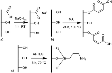 | ||
| Scheme 1 Functionalization methods of wood. a) Pretreatment with sodium hydroxide, b) functionalization with maleic anhydride, c) functionalization with (3-aminopropyl)triethoxysilane. In the cases of functionalization with MA and APTES only representative configurations are shown (see ESI† for more details). | ||
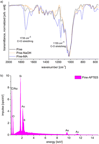
Functionalization with MA and APTES results in the formation of covalent bonds between the abundant hydroxyl groups and the functionalizing agent and leads to additional carboxylic acid or amine coordination sites for metal ions (Scheme 1b and c).47,50 Successful deprotonation by NaOH pretreatment is evidenced by the decreasing intensity of the carboxylic acid C![[double bond, length as m-dash]](https://www.rsc.org/images/entities/char_e001.gif) O-stretching vibration at 1735 cm−1 in the ATR-IR spectrum (Fig. 2a).32 Likewise, after esterification with MA, the same vibration increases in intensity due to the presence of more COOH-groups after functionalization (a slight shift to 1722 cm−1 is observed), which is furthermore visible with the increasing intensity of the band at 1155 cm−1 which is assigned to the C–O stretching in aliphatic esters.50 For functionalization with APTES, ATR-IR does not yield any significant identification of a successful reaction, since all expected Si–O-stretching and Si–O–CH3-rocking bands between 950 and 1200 cm−1 are masked by the vibrational peaks of the wood.56 Only the decrease of the OH-vibrational band at 3338 cm−1, as a result of the covalent bond between the hydroxyl-O and silicon, indicates the reaction (Fig. S3, ESI†). However, SEM–EDX can be used in this case to verify that silicon is present after the functionalization, which is evidenced by the prominent EDX peak at 1.74 keV (Fig. 2b). Additionally, the success of functionalization can be determined by the weight percent gain (WPG) (eqn (1)), which determines the increase in mass after functionalization compared to the weight before functionalization.49
O-stretching vibration at 1735 cm−1 in the ATR-IR spectrum (Fig. 2a).32 Likewise, after esterification with MA, the same vibration increases in intensity due to the presence of more COOH-groups after functionalization (a slight shift to 1722 cm−1 is observed), which is furthermore visible with the increasing intensity of the band at 1155 cm−1 which is assigned to the C–O stretching in aliphatic esters.50 For functionalization with APTES, ATR-IR does not yield any significant identification of a successful reaction, since all expected Si–O-stretching and Si–O–CH3-rocking bands between 950 and 1200 cm−1 are masked by the vibrational peaks of the wood.56 Only the decrease of the OH-vibrational band at 3338 cm−1, as a result of the covalent bond between the hydroxyl-O and silicon, indicates the reaction (Fig. S3, ESI†). However, SEM–EDX can be used in this case to verify that silicon is present after the functionalization, which is evidenced by the prominent EDX peak at 1.74 keV (Fig. 2b). Additionally, the success of functionalization can be determined by the weight percent gain (WPG) (eqn (1)), which determines the increase in mass after functionalization compared to the weight before functionalization.49
 | (1) |
Synthesis of neat MOFs
MIL-53(Al) was synthesized by the solvothermal reaction between aluminum nitrate and terephthalic acid in dimethylformamide. The experimental PXRD data match the simulation from the deposited structure files (Fig. 3a),57 except that the experimental diffraction peaks are broadened and slightly shifted to higher 2θ values compared to the simulated diffraction pattern which is caused by the lower synthesis temperature of 120 °C instead of the commonly used temperature of 220 °C.58 This low-temperature synthesis was chosen with regard to the synthesis of the MOF@wood composites, where a high temperature synthesis would cause thermal degradation of the wood matrix. As a result, the synthesized MIL-53(Al) crystallites are nanosized (as evidenced by SEM, Fig. S5, ESI†), which causes the diffraction peak broadening. Also, the low-temperature MIL-53(Al) contains a significant amount of mesopore defects (as evidenced by the pore size distribution from N2 sorption, Fig. S9, ESI†) which causes the diffraction peak shift.55,59 We assume that the lower synthesis temperature results in the formation of a defect-rich MIL-53(Al) with mesopores.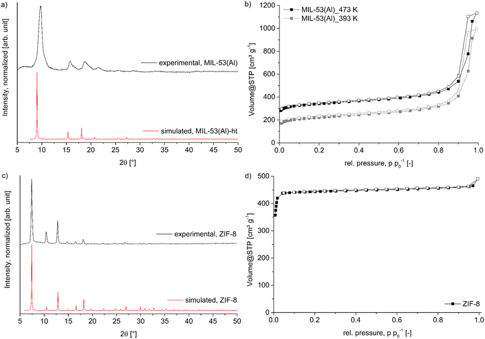 | ||
| Fig. 3 a) PXRD pattern of synthesized MIL-53(Al) compared to the simulated pattern of the ht-form (CSD-Refcode: SABVUN01, ref. 57). b) Nitrogen-sorption isotherms of MIL-53(Al) after degassing at 393 K and 473 K. c) PXRD pattern of synthesized ZIF-8 compared to the simulated pattern (CSD-Refcode: FAWCEN, ref. 61). d) Nitrogen-sorption isotherm of ZIF-8. For the nitrogen-sorption isotherms the filled symbols represent the adsorption branch, while the empty symbols represent the desorption branch. | ||
Nitrogen sorption measurements (Fig. 3b) of the synthesized material revealed a Brunauer–Emmett–Teller (BET) surface area of 1315 m2 g−1 when degassed at 200 °C (literature 1140–1520 m2 g−1).58,60 However, this degassing temperature will again not be applicable for the wood composites, therefore an additional N2 sorption with degassing at 120 °C was measured and resulted in a decreased BET surface area of 835 m2 g−1. This surface area will later be used as reference to compare to the composite materials. Pore size distribution shows a maximum at 12 Å, which corresponds well to the diagonal of the 8.5 × 8.5 Å channel opening in the ht-form of MIL-53(Al).58 The mesopores are most prominently distributed at around 160 Å. The MOF ZIF-8, was readily synthesized in a room temperature reaction between zinc nitrate and 2-methylimidazole in a mixture of methanol and water. The resulting PXRD (Fig. 3c) shows very good agreement with the simulated pattern, confirming the identity of the framework.61 The BET surface area determined by N2 sorption (Fig. 3d) revealed a specific surface area of 2100 m2 g−1 and a maximum in the pore size distribution (Fig. S10, ESI†) at 12 Å, in good agreement with the expected values of 1950 m2 g−1 and of 11.6 Å, respectively.62 SEM images (Fig. S6†) show the typical dodecahedral crystallites with a uniform size of approximately 1 μm.
Synthesis of MOF@wood composite materials
MOF@wood composite materials were synthesized the same way as the pristine MOFs, but with a preceding soaking of the wood with precursor solution. For MIL-53(Al), both precursors were dissolved in DMF and simultaneously soaked into the wood, since the MOF formed only at elevated temperatures. In the case of ZIF-8, the matrix was only soaked with the zinc-salt solution, since ZIF-8 precipitates immediately after adding the linker solution. However, this is not a problem, as the linker is used in a 20-fold molar excess and plenty of linker will be able to diffuse into the wood. For each MOF, four composite materials have been synthesized with Pine, Pine-NaOH, Pine-MA and Pine-APTES to compare the effect of different wood modification methods on the growth of MOFs with different metal coordination chemistry inside the lumen.The PXRD patterns for all MIL-53(Al)@wood composite materials (Fig. 4a) show the presence of a new diffraction peak in comparison to the pristine wood, which corresponds to the most intense reflection of MIL-53(Al) at 9.8 °2θ, indicating the successful in situ synthesis of the MOF inside the wood matrix. The wood itself includes two broad diffraction peaks centered around 16 and 22 °2θ which correspond to the reflections of semi-crystalline cellulose strands.50 When comparing the results of nitrogen sorption experiments (Fig. 4b), a more differentiated result unfolds. While the wood itself does not have a significant BET surface area, it is appreciably increased to 50 m2 g−1, 68 m2 g−1, 72 m2 g−1 and 92 m2 g−1 for MIL-53(Al)@Pine-APTES, MIL-53(Al)@Pine, MIL-53(Al)@Pine-NaOH and MIL-53(Al)@Pine-MA, respectively (Table 1). These results indicate, that the wood pretreatment has a significant influence on the amount of MOF that grows inside the matrix. As expected for the Al-carboxylate MOF, functionalization with carboxyl-forming MA results in the highest BET surface area, while functionalization with the amino-groups of APTES results in the lowest BET surface area. This indicates, that the functionalization method which provides the most metal coordination sites, has the highest positive influence on MOF growth. AAS measurements (Table 1) confirmed the BET results, with the sample MIL-53(Al)@Pine-MA containing the highest amount of aluminum or MOF. In the case of ZIF-8 composite materials, the opposite trend is seen for the Zn-nitrogen MOF with respect to APTES and MA. The PXRD data (Fig. 4c) clearly exhibits the characteristic reflections at 7.5, 10.5 and 12.8 °2θ except for the material ZIF-8@Pine-MA where no MOF diffraction peaks can be seen. For the composite ZIF-8@Pine-APTES, even the lower intensity diffraction peaks are clearly distinguishable, indicating a high amount of incorporated MOF inside the wood matrix due to the amino-anchor groups provided with APTES. These results are also in agreement with the determination of BET surface areas (Fig. 4d, Table 1) which increases from 1 m2 g−1 over 31 and 42 to 236 m2 g−1 for ZIF-8@Pine-MA, ∼@Pine, ∼@Pine-NaOH to ZIF-8@Pine-APTES, respectively. These results are again confirmed by AAS measurements (Table 1; for a MOF determination by TGA and SEM–EDX see section S11, ESI†). However, in the case of ZIF-8@Pine-MA, an increased amount of 7.9 wt% MOF was measured, while the BET surface area can be considered to be non-existent. We assume that the carboxylate groups still coordinate to the zinc ions, thereby making them unavailable for coordination of the 2-methylimidazole linker, thus preventing the formation of the ZIF structure. As a result, the determined amount of Zn2+ corresponds to carboxylate-bound metal ions which are not part of a ZIF structure. Again, as observed for MIL-53(Al), the wood functionalization which best mimics the metal coordination of the MOF results in the composite materials with the highest MOF loading. These results are in good agreement with the expectations from the HSAB concept (hard and soft acids and bases), where the comparably harder metal ion Al3+ coordinates better with the harder carboxylate groups provided by maleic anhydride, while the softer metal ion Zn2+ coordinates better with the softer amino groups introduced by the APTES functionalization. These results show, that a simple chemical modification of wood can strongly improve the targeted formation of MOF@wood composite materials with increased MOF loading compared to using pristine wood or only NaOH pretreated wood. A picture of the composite materials MIL-53(Al)@Pine-MA and ZIF-8@Pine-APTES is shown in Fig. S1 (ESI†).
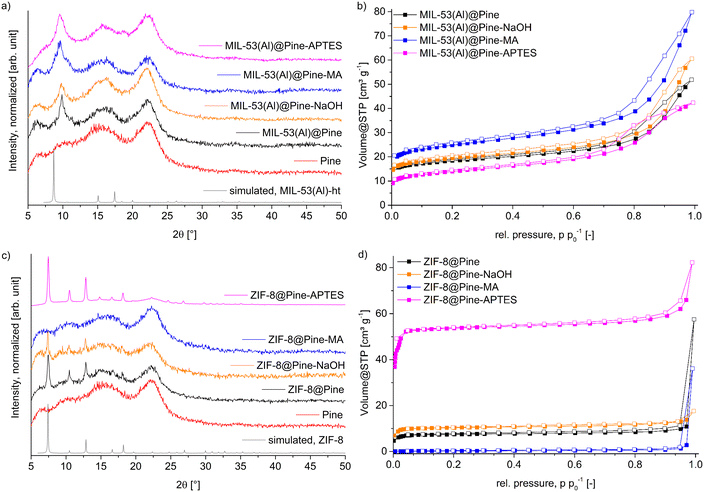 | ||
| Fig. 4 a) and c) PXRD patterns of MIL-53(Al) and ZIF-8@wood composite materials. Simulated patterns were obtained from the crystal structures of MIL-53(Al) (CSD-Refcode: SABVUN01)57 and ZIF-8 (CSD-Refcode: FAWCEN).61 b) and d) Nitrogen-sorption isotherms (at 77 K) of MIL-53(Al) and ZIF-8@wood composite materials. For nitrogen-sorption isotherms, the filled symbols represent the adsorption branch, while the empty symbols represent the desorption branch. | ||
| MOF | Matrix | BET surface area [m2 g−1] | Micro–/mesopore volume for pores ≤4 nm [10−2 cm3 g−1] | Amount MOF expected from BETa [wt%] | Amount MOF by AAS [wt%] |
|---|---|---|---|---|---|
| a Calculated by BETcomposite/BETMOF assuming that the wood matrix does not have a BET surface area (see section 9, ESI† for more details). For MIL-53(Al), the BET surface area of 835 m2 g−1 (after activation at 120 °C) was chosen. The BET surface area of ZIF-8 was 2100 m2 g−1. | |||||
| MIL-53(Al)@ | Pine | 68 | 2.3 | 8.2 | 7.1 |
| Pine-NaOH | 72 | 2.5 | 8.6 | 7.5 | |
| Pine-MA | 92 | 3.1 | 11.0 | 13.4 | |
| Pine-APTES | 50 | 1.6 | 6.0 | 4.3 | |
| ZIF-8@ | Pine | 31 | 1.1 | 1.5 | 2.1 |
| Pine-NaOH | 42 | 1.5 | 2.0 | 4.0 | |
| Pine-MA | 1 | 0.06 | 0 | 7.9 | |
| Pine-APTES | 236 | 7.6 | 11.2 | 13.4 | |
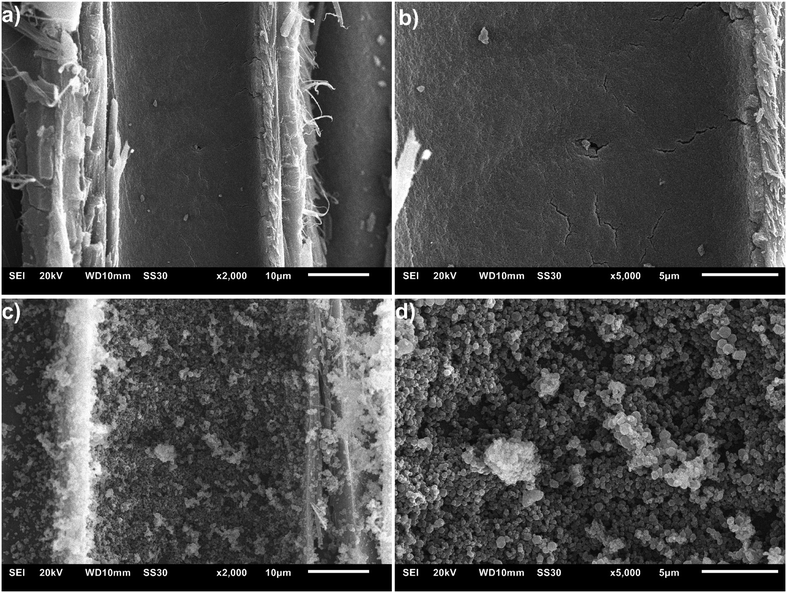
Scanning electron images (SEM) images were taken from freshly fractured cross-sections of the composite disks MIL-53(Al)@Pine-MA (Fig. 5a and b) and ZIF-8@Pine-APTES (Fig. 5c and d). For MIL-53(Al)@Pine-MA an even coating on the surface of the lumen can be seen which consist of particles smaller than 100 nm (a SEM image of pristine wood is shown in Fig. S7, ESI†). The thickness of this MOF layer can be estimated from Fig. 5 where at the right side of the image, a cross section of the MOF layer on the surface of the lumen is visible. Using the scale bar, a thickness of about 700 nm can be measured (see Fig. S8, ESI†). In the case of ZIF-8@Pine-APTES, the lumina are filled with larger particles of a size around 1 μm. Again, there is an even layer of particles across the surface of the lumen. In both cases, the successful in situ growth of MOF inside the wood matrix can be confirmed with SEM. It should be noted however, that this uniform coating could not be observed in all lumina channels across the sample. Since wood itself is a highly heterogeneous material, a homogeneous growth of MOF crystallites in the whole matrix cannot be ensured.
In their recently published review article, Ma et al. concluded that MOFs can fill wood lumina by three modes: (i) inner filler, (ii) inner cladding and (iii) inner anchor, with the inner anchor mode ensuring the highest uniformity and interaction.31 Our results show that this inner anchor mode can efficiently be achieved by chemical modification of the wood, resulting in a strong MOF-wood interaction and hence increased MOF-loading.
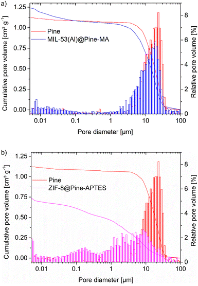
Mercury intrusion porosimetry (MIP) can be used to determine the amount of macropores and mesopores down to 4 nm (depending on the pressure) in a sample. The non-wetting liquid mercury is forced into the pores by increasing the pressure and thereby fills increasingly smaller pores. The pore size can then be calculated form the pressure using the Washburn equation (eqn (2)):
 | (2) |
In combination with the results from the pore size distribution from nitrogen sorption (Fig. S11–S12, ESI†) the MOF@wood composite materials show a hierarchically porous structure with micro-, meso- and macropores.
Sorption of methylene blue
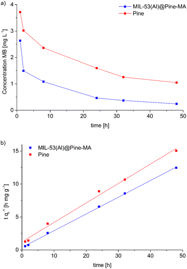
The composite material MIL-53(Al)@Pine-MA was tested for the sorption of the dye methylene blue (MB) from aqueous solution. Due to its large pore size, MIL-53(Al) is known to adsorb high amounts of methylene blue.53 In the first experiments, we compared the sorption capability of the materials when exposed to 20 mL of a MB solution with a concentration of 5 mg L−1 for 48 h. While the pristine wood is able to remove 90.4% of the MB (resulting in a sorption capacity of 1.5 mg g−1) the neat MOF itself is able to remove 95.0% of the MB at the given conditions (corresponding to a sorption capacity of 14.8 mg g−1). The functionalized wood Pine-MA showed no difference in MB removal and sorption capacity compared to the unfunctionalized wood, hence the following experiments were conducted only for the neat pine wood. Compared to this, the composite material MIL-53(Al)@Pine-MA was able to remove 98.4% of the MB under the same conditions, representing a sorption capacity of 1.7 mg g−1. Due to its porous structure, the wood itself is able to remove a large amount of MB. After the incorporation of MOF, the efficiency can be increased to near quantitative removal. When the amount of MB solution is increased to 50 mL, the difference becomes even more evident. In this case, the wood itself is able to remove 77.1% after 48 h (sorption capacity of 3.2 mg g−1) whereas the composite can remove 94.7% of the presents MB, equivalent to a sorption capacity of 3.9 mg g−1. Therefore, the effect of the incorporated MOF on the adsorption properties is clearly visible. Pictures of the discoloration of the MB solution for visualization can be found in the ESI.†Additionally, we studied the sorption kinetics of MB for the pine wood and the composite MIL-53(Al)@Pine-MA by taking aliquots after specific times (see Experimental section for details) and measuring the decrease in MB concentration (Fig. 7a). As can be seen, the MB concentration decreases by more than half after only 2 h in the case of MIL-53(Al)@Pine-MA, whereas the neat Pine wood takes nearly 8 h to reach this value. This indicates that the composite material not only shows an increased sorption capacity, but also increased sorption kinetics. To validate, the experimental data was fitted using pseudo second order kinetics in the linearized form (eqn (3)), the resulting fitting curves are shown in Fig. 7b.
 | (3) |
 | (4) |
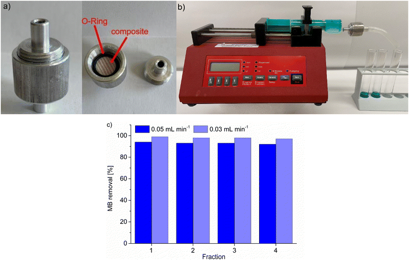
Following the static adsorption, we also tested the composite MIL-53(Al)@Pine-MA for the continuous filtration of MB from aqueous solution. To do so, we used a custom-made filtration capsule (Fig. 8a) into which the composite was mounted. Prior to the experiment, the composite was soaked in water to account for the tangential swelling of the wood in solution.64 This capsule was then connected to a syringe containing 20 mL of a 5 mg L−1 solution of MB, which was continuously pushed through the composite using a syringe pump at a pump rate of 0.05 mL min−1 (Fig. 8b). Four fractions of eluate were collected, one after every 5 mL of solution, and the remaining concentration of MB after filtration was analyzed using UV/VIS-spectroscopy (Fig. 8c). The removal is quite remarkable when compared to the static experiments, since the contact time of the solution with the adsorbent is drastically reduced. Considering the pump rate and the accessible volume of the composite (which is limited by the used O-ring with a diameter of 9 mm), a contact time of roughly only 4 minutes is calculated. Hence, the removal efficiency will even be increased when using slower pump rates and hence longer contact times. This was confirmed by repeating the experiment with a reduced pumping rate of 0.03 mL min−1 (and a resulting contact time of roughly 6.5 min), where the MB removal could be increased from 93 ± 1% to 98 ± 1% (Fig. 8c). This shows that the synthesized composite material could find potential applications in continuous water filtration and purification, which is exemplarily shown here with the adsorption of MB, especially when multiple composite disks are connected in series. Cui et al. tested their material for continuous MB filtration as well, reaching a removal of 94% when using a solution of 8 mg L−1 MB.63
Catalytic properties for the Knoevenagel condensation
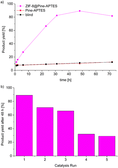
In the case of ZIF-8@Pine-APTES, we studied the ability of the material to heterogeneously catalyze the Knoevenagel condensation between benzaldehyde and malononitrile to form benzylidene malononitrile (Scheme 2), which is a known catalytic reaction for ZIF-8.54 To check the catalytic activity, the composite material, ZIF-8 or Pine-APTES were added to a vessel containing 1 mmol of each precursor in 2 mL of toluene and were allowed to react for 48 h at room temperature. Afterwards, the solution was analyzed by gas chromatography (GC). For ZIF-8@Pine-APTES, a conversion of 89% was observed for the given conditions, which corresponds well to the 85% conversion of neat ZIF-8. For Pine-APTES a low conversion of only 11% was determined. This product yield does not exceed that of the blind control test (precursors mixed without catalyst), hence the wood itself does not catalyze the Knoevenagel condensation between benzaldehyde and malononitrile. The MOF-modified wood composite shows a nine-fold higher activity compared to the Pine-APTES sample and the blind control, indicating the catalytic effect from the MOF.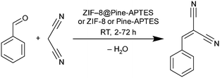 | ||
| Scheme 2 Reaction equation of the catalyzed Knoevenagel condensation between benzaldehyde and malononitrile to form benzylidene malononitrile. | ||
To determine the catalysis kinetics for ZIF-8@Pine-APTES, aliquots were taken from the reaction vessel after different times (see Experimental section for details) and analyzed via GC (Fig. 9a). For the Pine-APTES sample and the control, the product yield remains nearly constant after 5 h, indicating a low reactivity. For the composite ZIF-8@Pine-APTES, however, the product yield steadily rises up to a value of 89% after 48 h of reaction, showing that the MOF is the catalytically active component. If the reaction time is increased to 72 h, a reduction in product yield can be observed. We assume that this is caused by the product being adsorbed into the wood material after the catalysis is finished, thereby decreasing the concentration in the supernatant solution. We believe that combining ZIF-8 with the wood matrix offers two advantages: first the MOF is considered hydrophobic,65 thereby it facilitates the transport of the precursors dissolved in the non-polar solvent toluene into the wood matrix. Secondly, the wood matrix in contrast is hydrophilic, thereby it can easily adsorb the water that is formed during the condensation, shifting the reaction to the site of the products. In total, the material ZIF-8@Pine-APTES presents a hierarchically porous material with mixed hydrophilic-hydrophobic properties. Additionally, the product yield might possibly be increased by altering the synthesis conditions of the ZIF-8 particles inside the wood. Zhang et al. showed that the shape of ZIF-8 crystallites has a significant influence on the conversion during the Knoevenagel condensation, with ring-shaped crystallites achieving the highest conversion.66
Catalyst reusability was tested by washing the material in toluene and ethanol and repeating the catalysis with a duration of 48 h, the reusability was tested over 5 cycles (Fig. 9b). It becomes evident, that the catalytic activity strongly decreases after the first run. The product yield decreases from 89% during the first run to only 29% during the fifth catalysis run which was unexpected since the reusability of ZIF-8 for this reaction was already proven.54 A possible explanation might be that some of the incorporated MOF is washed out of the wood matrix during the reaction, indicating a weaker coordination of the MOF on the wood surface or that the product cannot be efficiently removed from the pores, thereby blocking the catalytically active centers. Hence, further experiments to increase the stability of the MOF@wood composite materials or to improve the washing seem to be necessary, but are out of the scope of this research.
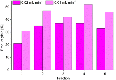
Following the static catalytic tests, we also conducted a continuous catalysis using the same setup as described for the continuous adsorption of MB by MIL-53(Al)@Pine-MA (Fig. 8a and b). Here, however, we used 5 mL of a solution of benzaldehyde and malononitrile (each 1 mol L−1) in toluene, which was pumped through the catalyst ZIF-8@Pine-APTES with a pump rate of 0.02 mL min.1. The composite was similarly soaked in toluene prior to the experiment. Five fractions were collected, one after every 1 mL of solution had been pushed through the catalyst, and the product yield was determined via GC (Fig. 10). For the first fraction, a product yield of 21% was determined. However, the concentration of the first fraction is reduced by the solvent that is trapped inside the wood after soaking, therefore the actual yield is higher. For the next four fractions, a nearly constant product yield around 35% was determined. Compared to the static catalysis, this value is again greater than expected for the short contact time of the precursor solution with the catalyst. Using the pump rate of 0.02 mL min−1, the thickness of the composite of 3 mm and the accessible diameter of 13 mm (limited by the O-ring), a contact time of only 20 minutes is calculated. For the static catalysis, a yield of 35% is not achieved even after 2 hours. Lei et al. synthesized a ZIF-8@melamin sponge composite material with up to 30 wt% MOF loading and achieved a nearly quantitative yield after 2 hours for the same reaction.67 Compared to our results with a contact time of only 20 minutes, the ZIF-8@Pine-APTES composite seems to slightly outperform the ZIF-8@melamin sponge material, with the former having a lower amount of MOF incorporated. Therefore, the continuous catalysis seems to increase the reaction kinetics, which is probably a result of the continuous flow created by the syringe pump. Again, the yield could probably be increased even further by either decreasing the pump rate or by using multiple MOF@wood composite disks in series. We again tested this by reducing the pump rate to 0.01 mL min−1 (achieving a contact time of 40 min). Again, for the first fraction a reduced conversion is observed, but for the following fractions, an increased yield of 47 ± 5% can be achieved (Fig. 10).
Conclusions
Herein, two easy methods were used to functionalize the surface of wood lumina with maleic anhydride (MA) and (3-aminopropyl)triethoxysilane (APTES). These functionalized wood samples were used to synthesize MOF@wood composite materials with increased MOF loading compared to pristine or NaOH-pretreated wood, reaching MOF loadings up to 13 wt% using the MOFs MIL-53(Al) and ZIF-8. It was shown that different functionalization methods have different effects on the MOF loading, depending on the used metal, according to the HSAB concept. The functionalization with MA creates more carboxylic acid groups which coordinate stronger to harder metal cations such as Al3+, whereas the functionalization with APTES creates additional amino groups on the surface of the lumina which coordinate stronger to softer metal cations such as Zn2+. The resulting composite materials show hierarchical porosity, combining micro- and mesoporosity of the MOFs and macroporosity of the wood. Furthermore, the composite materials show directional mass transport characteristics as a result of the anisotropic structure of the wood matrix.The resulting composite materials could potentially be used as filtration membranes or heterogeneous catalysts, which was shown in both static and continuous experiments. MIL-53(Al)@Pine-MA is able to efficiently remove 95% of methylene blue (MB) when exposed to 50 mL of 5 mg L−1 under static conditions for 48 hours. The composite shows both higher adsorption capacity and faster adsorption kinetics compared to the pristine wood. Furthermore, the composite material is able to remove more than 90% of MB in a 5 mg L−1 solution in continuous filtration experiments with contact times as short as 4 minutes. On the other hand, ZIF-8@Pine-APTES is able to catalyze the Knoevenagel condensation between benzaldehyde and malononitrile to form benzylidene malononitrile. While neither the pristine wood, nor the functionalized wood Pine-APTES show any conversion, the composite material yields 89% of the desired product after 48 h under static conditions. Catalyst reusability tests indicate a rather low stability of the composite ZIF-8@Pine-APTES with the yield dropping from 89% to 29% after five catalysis runs which might be a result of MOF leaching or pore blocking by the product. The composite was additionally tested for continuous catalysis, showing a yield of 35% after only 20 minutes of contact time. For both continuous experiments, MB removal and product yield can potentially be increased by slower pump rates or by using multiple composite disks in series.
Author contributions
Conceptualization A. S., C. J.; data curation A. S.; formal analysis A. S., J. W., E. I., D. W., C. J.; funding acquisition C. J.; investigation A. S., J. W., E. I., D. W.; methodology A. S.; project administration A. S., C. J.; resources C. J.; supervision C. J.; validation A. S.; visualization A. S.; writing – original draft A. S.; writing – review and editing A. S., C. J.Conflicts of interest
There are no conflicts to declare.Acknowledgements
C. J. is indebted to the DFG for funding within the priority program SPP 1928 “COORNET” (grant Ja466–43/1). The authors thank Mrs. Birgit Tommes for carrying out the FT-IR-experiments, Mrs. Annette Ricken for the AAS measurements and Mrs. Thi Hai Yen Beglau for helpful discussions.Notes and references
- S. R. Batten, N. R. Champness, X.-M. Chen, J. Garcia-Martinez, S. Kitagawa, L. Öhrström, M. O'Keeffe, M. Paik Suh and J. Reedijk, Pure Appl. Chem., 2013, 85, 1715–1724 CrossRef CAS
.
- H. Furukawa, K. E. Cordova, M. O'Keeffe and O. M. Yaghi, Science, 2013, 341, 1230444 CrossRef PubMed
.
- C. Janiak and J. K. Vieth, New J. Chem., 2010, 34, 2366 RSC
.
- K. Adil, Y. Belmabkhout, R. S. Pillai, A. Cadiau, P. M. Bhatt, A. H. Assen, G. Maurin and M. Eddaoudi, Chem. Soc. Rev., 2017, 46, 3402–3430 RSC
.
- M. H. Alkordi, Y. Belmabkhout, A. Cairns and M. Eddaoudi, IUCrJ, 2017, 4, 131–135 CrossRef CAS
.
- Y. He, W. Zhou, G. Qian and B. Chen, Chem. Soc. Rev., 2014, 43, 5657–5678 RSC
.
- K. Maru, S. Kalla and R. Jangir, New J. Chem., 2022, 46, 3054–3072 RSC
.
- X. H. Sihai Yang and M. Schröder, Nat. Rev. Chem., 2019, 3, 108–118 CrossRef
.
- J. Lee, O. K. Farha, J. Roberts, K. A. Scheidt, S. T. Nguyen and J. T. Hupp, Chem. Soc. Rev., 2009, 38, 1450–1459 RSC
.
- Y.-B. Huang, J. Liang, X.-S. Wang and R. Cao, Chem. Soc. Rev., 2017, 46, 126–157 RSC
.
- A. Herbst and C. Janiak, CrystEngComm, 2017, 19, 4092–4117 RSC
.
- S. K. Henninger, F. Jeremias, H. Kummer and C. Janiak, Eur. J. Inorg. Chem., 2012, 2012, 2625–2634 CrossRef CAS
.
- E. Hastürk, S.-J. Ernst and C. Janiak, Curr. Opin. Chem. Eng., 2019, 24, 26–36 CrossRef
.
- P. Horcajada, C. Serre, M. Vallet-Regí, M. Sebban, F. Taulelle and G. Férey, Am. Ethnol., 2006, 118, 6120–6124 Search PubMed
.
- P. Horcajada, R. Gref, T. Baati, P. K. Allan, G. Maurin, P. Couvreur, G. Férey, R. E. Morris and C. Serre, Chem. Rev., 2012, 112, 1232–1268 CrossRef CAS PubMed
.
- B. Valizadeh, T. N. Nguyen and K. C. Stylianou, Polyhedron, 2018, 145, 1–15 CrossRef CAS
.
- L. D. O'Neill, H. Zhang and D. Bradshaw, J. Mater. Chem., 2010, 20, 5720 RSC
.
- H. B. Tanh Jeazet, C. Staudt and C. Janiak, Dalton Trans., 2012, 41, 14003–14027 RSC
.
- E. Hastürk, C. Schlüsener, J. Quodbach, A. Schmitz and C. Janiak, Microporous Mesoporous Mater., 2019, 280, 277–287 CrossRef
.
- N. Stock and S. Biswas, Chem. Rev., 2012, 112, 933–969 CrossRef CAS PubMed
.
- F. Lorignon, A. Gossard and M. Carboni, Chem. Eng. J., 2020, 393, 124765 CrossRef CAS
.
- P. Su, W. Li, C. Zhang, Q. Meng, C. Shen and G. Zhang, J. Mater. Chem. A, 2015, 3, 20345–20351 RSC
.
- M. Plötze and P. Niemz, Eur. J. Wood Wood Prod., 2011, 69, 649–657 CrossRef
.
- M. Zauer, S. Hempel, A. Pfriem, V. Mechtcherine and A. Wagenführ, Wood Sci. Technol., 2014, 48, 1229–1240 CrossRef CAS
.
- T. Jelonek, K. Klimek, J. Kopaczyk, M. Wieruszewski, M. Arasimowicz-Jelonek, A. Tomczak and W. Grzywiński, Forests, 2020, 11, 980 CrossRef
.
- C. Chen, Y. Kuang, S. Zhu, I. Burgert, T. Keplinger, A. Gong, T. Li, L. Berglund, S. J. Eichhorn and L. Hu, Nat. Rev. Mater., 2020, 5, 642–666 CrossRef CAS
.
- L. A. Berglund and I. Burgert, Adv. Mater., 2018, 30, e1704285 CrossRef PubMed
.
- J. Ralph, C. Lapierre and W. Boerjan, Curr. Opin. Biotechnol., 2019, 56, 240–249 CrossRef CAS PubMed
.
- C. Jia, Y. Li, Z. Yang, G. Chen, Y. Yao, F. Jiang, Y. Kuang, G. Pastel, H. Xie, B. Yang, S. Das and L. Hu, Joule, 2017, 1, 588–599 CrossRef
.
- J. E. Jakes, C. G. Hunt, S. L. Zelinka, P. N. Ciesielski and N. Z. Plaza, Forests, 2019, 10, 1084 CrossRef
.
- X. Ma, Y. Xiong, Y. Liu, J. Han, G. Duan, Y. Chen, S. He, C. Mei, S. Jiang and K. Zhang, Chem, 2022, 8, 1–20 Search PubMed
.
- K. Tu, B. Puértolas, M. Adobes-Vidal, Y. Wang, J. Sun, J. Traber, I. Burgert, J. Pérez-Ramírez and T. Keplinger, Adv. Sci., 2020, 7, 1902897 CrossRef CAS PubMed
.
- M. Su, R. Zhang, H. Li, X. Jin, J. Li, X. Yue and D. Qin, RSC Adv., 2019, 9, 40277–40285 RSC
.
- R. Guo, X. Cai, H. Liu, Z. Yang, Y. Meng, F. Chen, Y. Li and B. Wang, Environ. Sci. Technol., 2019, 53, 2705–2712 CrossRef CAS
.
- Y. Lu, D. Fan, Z. Shen, H. Zhang, H. Xu and X. Yang, Nano Energy, 2022, 95, 107016 CrossRef CAS
.
- Z. Wang, Y. He, L. Zhu, L. Zhang, B. Liu, Y. Zhang and T. Duan, Mater. Chem. Phys., 2021, 258, 123964 CrossRef CAS
.
- K. Tu, S. Büchele, S. Mitchell, L. Stricker, C. Liu, C. Goldhahn, J. Allaz, Y. Ding, R. Günther, Z. Zhang, J. Sun, S. Stucki, G. Panzarasa, S. C. Zeeman, I. Burgert, J. Pérez-Ramírez and T. Keplinger, ACS Appl. Mater. Interfaces, 2022, 14, 8417–8426 CrossRef CAS PubMed
.
- S. Wang, C. Wang and Q. Zhou, ACS Appl. Mater. Interfaces, 2021, 13, 29949–29959 CrossRef CAS PubMed
.
- L. Xu, Y. Xiong, B. Dang, Z. Ye, C. Jin, Q. Sun and X. Yu, Mater. Des., 2019, 182, 108006 CrossRef CAS
.
- M.-B. Wu, C. Zhang, Y. Xie, S. Huang, C. Liu, J. Wu and Z.-K. Xu, ACS Appl. Mater. Interfaces, 2021, 13, 51039–51047 CrossRef CAS PubMed
.
- W. Zhang, M. Li, L. Zhong, J. Huang and M. Liu, Mater. Today Energy, 2022, 24, 100951 CrossRef CAS
.
- H. Qin, Y. Zhou, Q. Huang, Z. Yang, R. Dong, L. Li, J. Tang, C. Zhang and F. Jiang, ACS Appl. Mater. Interfaces, 2021, 13, 5460–5468 CrossRef CAS PubMed
.
- R. Tian, C. Duan, Y. Feng, M. Cao and J. Yao, Energy Fuels, 2021, 35, 4604–4608 CrossRef CAS
.
- X. Ma, S. Zhao, Z. Tian, G. Duan, H. Pan, Y. Yue, S. Li, S. Jian, W. Yang, K. Liu, S. He and S. Jiang, Chem. Eng. J., 2022, 446, 136851 CrossRef CAS
.
- G. Huang, C. Huang, Y. Tao and H. Li, Appl. Surf. Sci., 2021, 564, 150325 CrossRef CAS
.
- L. B. de Taillac, M. C. Porté-Durrieu, C. Labrugère, R. Bareille, J. Amédée and C. Baquey, Compos. Sci. Technol., 2004, 64, 827–837 CrossRef
.
- H. Khanjanzadeh, R. Behrooz, N. Bahramifar, W. Gindl-Altmutter, M. Bacher, M. Edler and T. Griesser, Int. J. Biol. Macromol., 2018, 106, 1288–1296 CrossRef CAS PubMed
.
- C.-A. Teacă, R. Bodîrlău and I. Spiridon, Cellul. Chem. Technol., 2014, 48, 863–868 Search PubMed
.
- S. Vitas, T. Keplinger, N. Reichholf, R. Figi and E. Cabane, J. Hazard. Mater., 2018, 355, 119–127 CrossRef CAS PubMed
.
- C. Montanari, P. Olsén and L. A. Berglund, Green Chem., 2020, 22, 8012–8023 RSC
.
- A. Huang, H. Bux, F. Steinbach and J. Caro, Angew. Chem., Int. Ed., 2010, 49, 4958–4961 CrossRef CAS PubMed
.
- Z. Xie, J. Yang, J. Wang, J. Bai, H. Yin, B. Yuan, J. Lu, Y. Zhang, L. Zhou and C. Duan, Chem. Commun., 2012, 48, 5977–5979 RSC
.
- C. Li, Z. Xiong, J. Zhang and C. Wu, J. Chem. Eng. Data, 2015, 60, 3414–3422 CrossRef CAS
.
- U. P. N. Tran, K. K. A. Le and N. T. S. Phan, ACS Catal., 2011, 1, 120–127 CrossRef CAS
.
- W. P. Mounfield III and K. S. Walton, J. Colloid Interface Sci., 2015, 447, 33–39 CrossRef PubMed
.
- A. Bragaru, M. Kusko, A. Radoi, M. Danila, M. Simion, F. Craciunoiu, R. Pascu, I. Mihalache and T. Ignat, Open Chem., 2013, 11, 205–214 CAS
.
- Y. Guo, J. Zhang, L.-Z. Dong, Y. Xu, W. Han, M. Fang, H.-K. Liu, Y. Wu and Y.-Q. Lan, Chem. – Eur. J., 2017, 23, 15518–15528 CrossRef CAS PubMed
.
- T. Loiseau, C. Serre, C. Huguenard, G. Fink, F. Taulelle, M. Henry, T. Bataille and G. Férey, Chem. – Eur. J., 2004, 10, 1373–1382 CrossRef CAS PubMed
.
- X.-D. Do, V.-T. Hoang and S. Kaliaguine, Microporous Mesoporous Mater., 2011, 141, 135–139 CrossRef CAS
.
- H. R. Abid, Z. H. Rada, J. Shang and S. Wang, Polyhedron, 2016, 120, 103–111 CrossRef CAS
.
- W. Morris, C. J. Stevens, R. E. Taylor, C. Dybowski, O. M. Yaghi and M. A. Garcia-Garibay, J. Phys. Chem. C, 2012, 116, 13307–13312 CrossRef CAS
.
- K. S. Park, Z. Ni, A. P. Côté, J. Y. Choi, R. Huang, F. J. Uribe-Romo, H. K. Chae, M. O'Keeffe and O. M. Yaghi, Proc. Natl. Acad. Sci. U. S. A., 2006, 103, 10186–10191 CrossRef CAS PubMed
.
- Z. Cui, J. Wu, Y. Xu, T. Wu, H. Li, J. Li, L. Kang, Y. Cai, J. Li and D. Tian, Chem. Eng. J., 2023, 451, 138371 CrossRef CAS
.
- G. I. Mantanis, R. A. Young and R. M. Rowell, Holzforschung, 1994, 48, 480 CrossRef CAS
.
- K. Zhang, R. P. Lively, C. Zhang, R. R. Chance, W. J. Koros, D. S. Sholl and S. Nair, J. Phys. Chem. Lett., 2013, 4, 3618–3622 CrossRef CAS
.
- P. Zhang, Y. Xiao, H. Sun, X. Dai, X. Zhang, H. Su, Y. Qin, D. Gao, A. Jin, H. Wang, X. Wang and S. Sun, Cryst. Growth Des., 2018, 18, 3841–3850 CrossRef CAS
.
- Z. Lei, Y. Deng and C. Wang, J. Mater. Chem. A, 2018, 6, 3258–3263 RSC
.
Footnote |
| † Electronic supplementary information (ESI) available: List of used chemicals, known MOF@wood materials, side reactions upon wood functionalization, structure of MIL-53 and ZIF-8, SEM images, N2 isotherms and pore size distributions, methylene blue adsorption isotherm modelling, TGA. See DOI: https://doi.org/10.1039/d2me00163b |
| This journal is © The Royal Society of Chemistry 2022 |

