 Open Access Article
Creative Commons Attribution 3.0 Unported Licence
Tribocharged granular assembly of polystyrene beads confined between plates using acoustic vibrations†
Arely G.
Jiménez-Díaz
 a,
Ignaas S. M.
Jimidar
 *bc and
Fernando
Donado-Pérez
 *a
*a
aInstituto de Ciencias Básicas e Ingeniería de la Universidad Autónoma del Estado de Hidalgo-AAMF, Pachuca 42184, Hidalgo, Mexico. E-mail: fernando@uaeh.edu.mx
bDepartment of Chemical Engineering CHIS, Vrije Universiteit Brussel, Brussels, 1050, Belgium. E-mail: ignaas.jimidar@vub.be
cMesoscale Chemical Systems, MESA+Institute, University of Twente, P.O. Box 217, 7500AE Enschede, The Netherlands. E-mail: i.s.m.jimidar@utwente.nl
First published on 13th November 2024
Abstract
In this work, we investigate the transition from an amorphous state to crystal ordering of 3 mm-sized polystyrene beads in a two-dimensional system between two plates, one of them fixed and the other is mobile and can move across the beads. The system is vibrated vertically, and we have investigated the effect of the frequency, the number of particles, and the different materials covering the bottom and top plate. We found that crystallisation is promoted by the motion of the upper plate, which pushes particles to the centre of the plate's configuration and by the onset of tribocharged-induced electrostatic interactions. The motion of the upper plate creates an effective pressure over the particles. Thus, the upper plate motion drives the ordered particle configuration, and electric charges stabilise it. By changing the bottom plate surface and experimenting with steel balls, we found that strong charging can demote crystal formation, and no charging inhibits crystal formation.
1. Introduction
Crystallisation is ubiquitously present in nature. Therefore, research on ordered systems has captivated scientists for centuries as these studies are essential in the fundamental understanding of the formation of crystals, glasses, polycrystals, and many other systems belonging to the condensed soft matter.1–5Ordering in systems is intrinsically governed by attractive and repulsive forces among the systems’ constituents. Still, external perturbations can notably affect it, which can drive or prevent ordered particle configurations. Vibrations, pressure, electric fields and shearing can be considered among these perturbations.6–9 These external factors can be exploited to control phase transitions or change a system's general ordering.
A detailed description of the crystallisation process occurring at the particle level at the microscale, or even smaller, is highly complex and challenging as size and temporal resolutions need to be acquired in these studies. Also, microscopic and colloidal particles in the dry state suffer from strong cohesive and adhesive interactions,10–13 adding to the complexity of studying their self-organisation. Nevertheless, the assembly of dry colloidal powders using rubbing,14–17 horizontal agitation10 or electric-field driven18 has been recently reported. Also, efforts are being made to study the assembly of microscopic spheres using acoustic levitation.19,20
On the other hand, macroscopic systems, besides their own importance, can serve as suitable models for processes that happen at the microscopic level.21 Some studies in macroscopic systems have addressed this general goal. For instance, a combination of vibration, sedimentation, and shearing is used to obtain crystal configuration in systems based on spheres or cubes.6,7 Some works have addressed the nucleation process, while the Whiteside group explored the formation of binary coulombic crystals by vibrating two different mm-sized polymer spheres.22–24
In contrast to microscopic systems, macroscopic systems encompass a great advantage as their temporal and spatial characteristic lengths can be quantified by tracking each particle using standard video microscopy. This data can be analysed to subsequently calculate the orientational and spatial order parameters, which can be utilised to determine the degree of order of the particle configurations.
In previous studies,25–27 the ordering and phase behaviour of a thin layer of steel balls has been explored between a bottom plate and a fixed lid that was place over a certain distance (>1.5 × particle diameter) from the bottom plate. Here, we present a study of crystallisation in a vibrated 2D-dimensional granular system of polystyrene beads between two plates: the bottom plate is fixed or immobilised, and the other is free and sits on top of the particles, i.e., the distance between the plates before the vibration experiments start is exactly one particle diameter. The ordering is promoted by vibration and is stabilised by triboelectric-induced charging. As we elaborate, the free plate creates an effective pressure over the particles and, combined with vibration, drives the system to ordered states. We perform an extensive investigation of the crystallisation of the system under varying conditions of frequencies and particle number and utilise different material plate combinations. This uncharted crystallisation mechanism could be used in packing and storage processes for granular systems to increase the volume fraction, reaching crystallisation ordering with arrangements that minimise empty spaces. In flowing problems where ordering influences the flowing properties, external perturbations such as vibrations, as we used in this work, could promote easy flow. Granular crystals could be used as modular structural materials with enhanced mechanical properties compared to traditional materials. Topologically interlocked, ordered structures display enhanced mechanical properties when forming panels, thin 2D and 3D structures. Their properties depend in a complex way on the geometry of the individual grains, their orientation, and the friction between their surfaces. Vibration is a way to promote self-assembly, but other mechanisms, such as triboelectricity, shearing and strong confinement could also be used.6,7,21,28–30
The manuscript is organised as follows: Section 2 describes the experimental details, and the construction of the sixth orientational order parameter is provided. Section 3 presents the crystallisation results for several configurations and the temporal evolution of the sixth-orientational-order parameter ψ6. Finally, in Section 4, the conclusions and perspectives of this work are given.
2. Experimental details
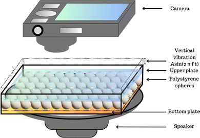
The system depicted in Fig. 1 comprises a planar square cell with an inner width of 70 mm surrounded by acrylic walls. The cell's bottom surface is made of glass and rigidly attached to a 6.5′′ Kenwood speaker. An additional thin plate of various materials is glued over the glass cell surface in the experiments. This thin plate is referred to as the bottom plate. Over the bottom plate, an ensemble of polystyrene spheres of 3 mm in diameter, d, is distributed; in the experiments, the number of particles varies. On top of the particles, another plate (usually glass) of 68 mm in width is allocated, such that the plate can move freely and may touch the particles; we refer to this plate as the upper plate. Also, no liquid or solvent is added in this cell, such that experiments are performed in air. Using an A(f)sin(2πft) signal with a frequency fixed in each experiment, we keep the system vibrating to compensate for the energy lost by dissipative processes and maintain an effective temperature. A camera (Canon DC4 3V) was employed to capture the beads' dynamics during the experiment. We recorded a 200-second video in AVI format at a standard resolution of 640 × 480 pixels at 30 fps. In the videos [system before of the upper plate] and [system with the upper plate] in ESI,† an experiment shows the particle motion without the upper plate and the motion and crystal formation after the upper plate was added.For the fabrication of indium tin oxide (ITO) and fluorocarbon-coated MEMPAX substrate, we refer the interested reader to earlier work.14 In some experiments, MEMPAX was used as the bottom plate. MEMPAX is a borosilicate glass substrate with mobile sodium ions for anodic bonding purposes.31
3. Results
3.1. The effect of the mobile upper plate on crystallisation
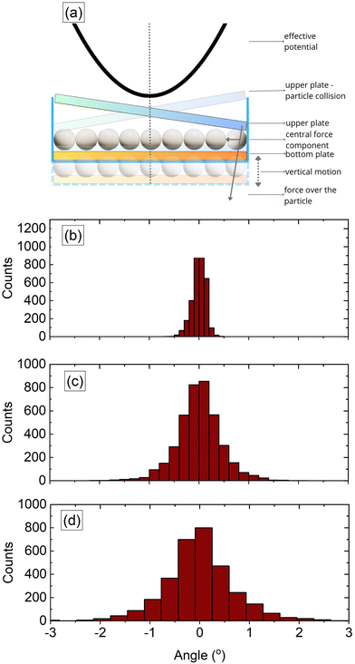
To rationalise the crystallisation mechanism observed in our experiments, we conducted experiments to determine the effects of the upper plate's vibration and how its motion promotes crystallisation. To our knowledge, studies of beads covered by a mobile plate precisely on top of them on a vibrating platform are unexplored. Instead, we found related studies that helped us understand the crystallisation mechanism. Dorbolo et al.32 reported a study of a dimer on a vibrating platform and observed three possible motions of the dimer. In one mode, the dimer bounces parallel to the plate; in the other mode, the dimer oscillates; in the third mode, the dimer drifts, keeping one end in contact with the plate and the other oscillating. In our experiment, the motion of the top plate and the particles against it corresponded to the first two modes in a 3D version (Fig. 2).The effective force by the upper plate on the particle layer in our system is illustrated in Fig. 2 when the system is vibrating vertically. Note that the upper plate does not remain in a fixed horizontal position while the system vibrates vertically. As such, during the experiments, the upper plate is inclined, first hitting the distant particles and pushing them to the centre. Of course, the direction of the effective pushing changes while the experiment runs. Thus, similar to Dorbolo et al.,32 it is understood that the main effect is to create an effective potential that drives particles to occupy a minimum energy configuration centred below the plate's centre of mass.
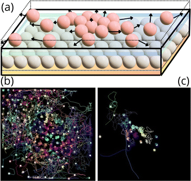
To corroborate that in the experiments, the upper plate created an effective potential driving the beads to the centre of the plate, we placed a second layer of particles on the top at the other side of the mobile upper plate, as shown in Fig. 3(a), such that this particle layer is not confined at the top. When the system vibrated, the second layer's particles were also fluidised and moved around, as shown in Fig. 3(b). Because these particles were not forced to move between plates, they experienced larger jumps as they were farther from the plate's centre. Interestingly, the particles close to the centre of the plate moved less than the particles near the edges of the upper plate. Eventually, most of the particles of this second layer were expelled from the container. Still, a few remained in the plate's centre, as shown in Fig. 3(c). Thus, the upper plate centre moves less than the plate edges and sides as it oscillates around its centre. The effect on the particles below the plate is the kicks toward the centre of the plate, creating an effective restitutive force or soft potential toward the centre of the plate.
In addition, lateral view recordings confirmed that the upper plate did not always move parallel to the bottom plate but got inclined and oscillated around its centre of mass, changing the direction of inclination as the system vibrated, see Fig. 2(b) and Video [upper plate movement] in ESI.† It can be observed that the plate centre moved relatively less than its corners and sides, which supports the observation that particles on the upper plate farther from the centre were expelled from the container, whereas particles in the centre remained there. On the other hand, the confined particles beneath the upper plate and farther from the centre experienced an effective lateral pressure when the upper plate hit them during the plate's inclination phase (cf.Fig. 2). This effective pressure pushes the particles to the centre of the box.
We use the dimensionless Γ parameter to characterise the system's vibration, showing the ratio between the acceleration of the system and the acceleration due to gravity, g. It is defined as follows:
 | (1) |
Besides the mechanical interactions between the upper plate and the particles, which is the primary interaction, the system's dynamics are governed by the particle–particle interactions, which are hard-sphere interactions when no charge is present. As the particles move across and hit the plates, they also experience friction.33 Furthermore, as the beads and plates are in frictional contact, the triboelectric charging phenomenon,34–38 in which charge is exchanged between bodies in contact, occurs. This may lead to attractive Coulombic forces between the beads and the plates and repulsive Coulombic interactions between the beads if they have the same polarity. Depending on the material of the plates, the electric charge can stabilise a particle configuration or prevent ordering if particles get stuck to the plates. It should also be remarked that the triboelectric charging may cause charge patches on the beads, such that only the areas in contact with the plates get charged, i.e., the bead surface is not uniformly charged.35,39,40
We characterised the configurational order of a system with n particles in terms of the sixth orientational order parameter ψ6 for each particle and its average value  , calculated as follows (cf.eqn (2)). First, we acquired each particle's position by capturing the centre of mass using the image processing software ImageJ.41 Then, we triangulated all mass centre positions following the Delaunay criterion to find the closest neighbours Ni for each particle i. We established a cut-off distance, as the size of a sphere diameter, to determine the nearest neighbours in contact with each particle i, its coordination number, NiB.42 We proceed to calculate the average of the six-fold bond-orientation, or hexatic, order parameter
  as expressed in eqn (2).
 | (2) |
In the next subsections, the effect of two different top plates, namely glass and ITO, on the ordering of the beads is delineated. Next, we elaborate on the influence of the bottom's plate material and the effect of residual charge on the attained order of the shaken polystyrene beads.
3.2. Glass–Glass plates
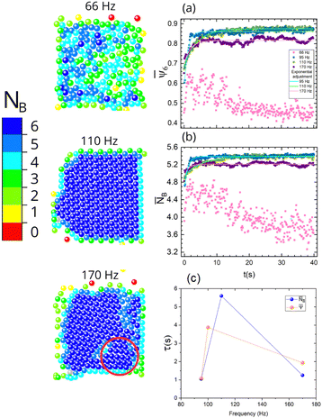
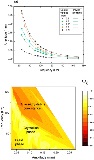
In Fig. 4, we present coloured maps where each particle position is coloured according to its coordination number at different frequencies for a fixed number of particles where both the bottom and upper plate were made of glass, i.e., the glass–glass combination, see, for instance, videos [290 66 Hz G–G], [290 100 Hz G–G] and [290 170 Hz G–G]. Note that increasing the frequency in our system leads to lower plate vibration amplitudes (cf.Fig. 5a), decreasing the system's energy. Thus, the fluidization of the granular media prevents the ordering at lower frequencies, i.e., high-energy systems. As the frequency increased, the fluidization decreased, and the system manifested a higher order. It can be inferred from Fig. 4 that the system reached its maximum order at frequencies around 110 Hz, whereas for frequencies around 170 Hz, the system presented some defects and vacancies. For lower and higher frequencies with respect to 110 Hz, the formation of a main grain and one or more additional grains oriented differently can be observed, preventing full ordering. Fig. 4 shows a grain enclosed by a red ellipse that has a different orientation from the main grain.
Fig. 4a and b displays the time behaviour of the average of the sixth orientational order parameter,  , and the average of the coordination number,
 ![[N with combining macron]](https://www.rsc.org/images/entities/i_char_004e_0304.gif) B, for different frequencies, showing similar temporal behaviour for both quantities. A sharp initial increase is observed, reaching a saturation value. It can be readily observed that the system did not reach ordering at a frequency of 66 Hz due to the high fluidization energy preventing ordering. It can be inferred that similar saturation values reached 95 Hz and 110 Hz, although the 95 Hz case reached this condition faster.
B, for different frequencies, showing similar temporal behaviour for both quantities. A sharp initial increase is observed, reaching a saturation value. It can be readily observed that the system did not reach ordering at a frequency of 66 Hz due to the high fluidization energy preventing ordering. It can be inferred that similar saturation values reached 95 Hz and 110 Hz, although the 95 Hz case reached this condition faster.
To quantify how fast saturation values were reached, we used the following fitting
 | (3) |
 or
or ![[N with combining macron]](https://www.rsc.org/images/entities/i_char_004e_0304.gif) B and t is the time and τ is the characteristic time. For
B and t is the time and τ is the characteristic time. For ![[N with combining macron]](https://www.rsc.org/images/entities/i_char_004e_0304.gif) B curves and for 95, 110 and 170 Hz, the corresponding τ values are 1.05, 5.60 and 1.25 s, respectively. For the
B curves and for 95, 110 and 170 Hz, the corresponding τ values are 1.05, 5.60 and 1.25 s, respectively. For the  curves, the τ values are 1.09, 3.88 and 1.94 s for 95, 100 and 170 Hz, respectively (cf.Fig. 4d). These characteristic time scales corroborate that, indeed, the order is reached more rapidly in the 95 Hz case. The lower energy system at 170 Hz case also rapidly becomes ordered, albeit less than the 95 Hz case. Additionally, more fluctuations can be observed than in the cases of 95 Hz and 110 Hz, elucidating that more perturbations of the ordered grain structure occur over time.
As mentioned before, the parameter Γ depends on the frequency f and amplitude A of the lower plate motion, and a separate control of both quantities is challenging in our system. The amplitude A depends on the speaker's response and, thus, is not controlled directly by the voltage control signal. Therefore, comparing results is not evident. We have carried out a series of experiments for several fixed frequencies, and by varying the amplitude of the voltage that feeds the speaker, we determine the parameter Γ and the orientational order parameter. Using eqn (1), we obtained the amplitude A. Fig. 5a shows that when the frequency was increased, the amplitude in the system decreased, and concurrently the decrement in the parameter Γ value is more significant than the increment due to the frequency. Fig. 5b shows a coloured map that is coloured according to the orientational order parameter. We observed that intermediate values of the parameter Γ promote crystallization observed in the region coloured in yellow. For high parameter Γ (=high amplitude and low frequency), the system presents the coexistence of a central crystalline configuration surrounded by a gas-like state. The system remains in a solid glass-like state configuration for low parameter Γ (low amplitude). Crystallization is observed for intermediate values of parameter Γ and intermediate frequencies. The coexistence of glass and crystalline phases is observed for intermediate values of parameter Γ and high frequency. The glass-like state and crystalline state can also be observed in g(r) curves (see Fig. 11(a) and (b) in Appendix). For the glass-like state in Fig. 11(a), some peaks in the g(r) around sizes that are multiples of particle diameter are observed, after which the curve approximates unity. For the crystalline state, the peaks are almost down until zero values are observed, and two close peaks around two particle sizes are observed, which is the footprint of a hexagonal arrangement.
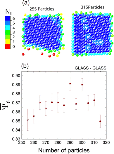
Next, we studied the effect of the number of particles on the system's ordering while keeping a fixed frequency. Fig. 6(a) compares two cases with different numbers of particles for a constant frequency at 110 Hz. For the case of 315 particles, some crystalline defects can be observed. Fig. 6(b) shows the behaviour of the order parameter as a function of particle number. We have observed that  increases as the frequency increases. However, for more than 295 particles, some defects in the attained structures can be noticed and the values of
  tend to decrease. Particularly, the formation of at least two grains separated by disordered boundaries can be observed. The grains presented limited mobility for systems with many beads because they were stuck, so the arrested beads could not dissolve the disordered boundaries. When more free space is available, particles are easily reordered because the fluidisation mechanism is more efficient than in cases where the particle's mobility is restricted by strong spatial confinement.
In open spaces where another substrate at the top does not cover the beads, increasing the particle concentration leads to the ordering of the particles.43,44 In confined conditions, as studied here, increasing the particle concentration promoted the ordering. The complete order, i.e., when each particle has a value of ψ6 = 1, is reached only if there is a commensurability between the particle size and the dimensions of the container. Without commensurability, the system's ordering could be high, but the complete order is not reached. For instance, there is no commensurability between a hexagonal arrangement and circular and square containers.45–49 Thus, complete order in our system could be reached if we used a hexagonal container where the container side is multiple of the particle size see video [hexagonal geometries] in ESI.† It reached a complete order in the biggest hexagonal container, where the container side is a multiple of the particle size. At the same time, in the smallest one, it did not because the container size is not a multiple of the particle size.
When the available free space is limited, the ordering driven by vibrations is prevented because particles are in jammed configurations, i.e., stuck in an ordered or disordered local configuration, forming grains separated by disordered boundaries.48 To attain larger ordered configurations, particles should be able to explore their surroundings to minimize the configurational energy. However, finding such minimum energy configurations remains elusive when free space is severely limited.
3.3. Glass–ITO plates
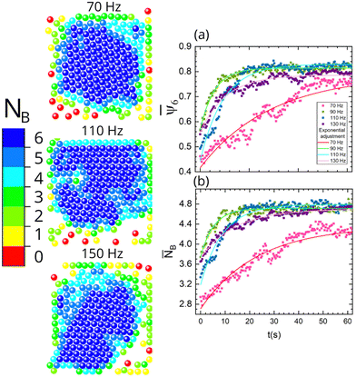
In the next set of experiments, we changed the upper plate with a MEMPAX substrate coated with a layer of indium tin oxide (ITO), while the bottom plate was still made of glass. Fig. 7 displays the final configuration for different frequency cases for the glass–ITO combination. It can be observed that the system already reached an ordered state at 70 Hz, while almost complete ordering is attained at 90 Hz. As the frequency increases, similar ordering is obtained, albeit some imperfections hinder complete order.We define the ordered particle crystal configurations in all experiments as an aggregate. In contrast to the glass–glass case, higher aggregate mobility was observed in the glass–ITO case; see video [upper plate L-GLASS R-ITO lower plate glass 250P 100 Hz] in ESI.† This distinct observation can plausibly be ascribed to tribocharging-driven electrostatic interactions. As mentioned earlier, tribocharging may occur as the beads are in frictional contact with the upper and bottom plates. Since ITO is conductive,14 weaker charging is expected in the glass–ITO case than in the glass–glass case,35 recently reported by Sotthewes et al.14 using Kelvin prove force microscopy (KPFM). Thus, in the latter case, the stronger tribocharging and concomitant attractive Coulombic interactions stabilized the aggregate, leading to lower mobility and higher stability of the particle crystal configuration.10
Fig. 7 shows the behaviour of the average of the sixth orientational order parameter and the average of the coordination number. Only for the case of 70 Hz, both parameters have low values, i.e., the system contained defects in the formed crystal structure, whereas the other cases have similar values. For ![[N with combining macron]](https://www.rsc.org/images/entities/i_char_004e_0304.gif) B curves at 70, 95, 110, and 130 Hz, the corresponding τ values are 22.9, 5.31, 8.9, and 13 s, respectively. Thus, as the frequency increases, ordering in the system is slower.
B curves at 70, 95, 110, and 130 Hz, the corresponding τ values are 22.9, 5.31, 8.9, and 13 s, respectively. Thus, as the frequency increases, ordering in the system is slower.
3.4. Other combination plates cases
To investigate how the bottom plate's conductivity affects the system's order, we performed experiments by changing the bottom plate and keeping the upper plate as glass or ITO. It is known that all these three bottom substrates (glass, Mempax, and Mempax + FC) tend to tribocharge, particularly the fluorocarbon surface can gain a strong tribocharged state.14,15,50 Based on the triboelectric series,34,35 different polarities can be predicted on the beads and the bottom and top plates, which are summarised in Table 1. Note that no charge was previously measured on the conductive ITO-coating and is therefore identified as neutral.14 The top side of the bead may acquire a negative polarity but can also discharge some of its charge through the ITO-coated surface, leading to weaker charging.14 On the other hand, the combination which involved the utilisation of a fluorocarbon-coated substrate illustrates a significant case where the top and bottom part of the polystyrene bead are expected to gain an opposite polarity, such that the final charge on the polystyrene bead can not be predicted. This fluorocarbon-coated case signifies that the polymer bead can acquire charge patches,35,39i.e., different polarities on the same particle surface.| Pair | Bottom | Top | Bead | Net charge on bead |
|---|---|---|---|---|
| Glass–glass | + | + | −/− | − |
| Glass–ITO | + | 0 | −/− | − |
| Mempax–glass | + | + | −/− | − |
| Mempax–ITO | + | 0 | −/− | − |
| Mempax + FC-Glass | − | + | +/− | × |
| Mempax + FC-ITO | − | 0 | +/− | × |
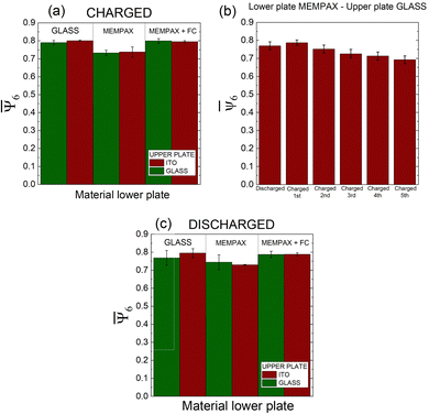
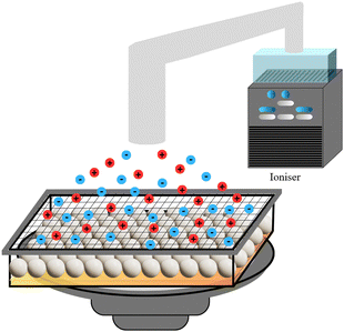
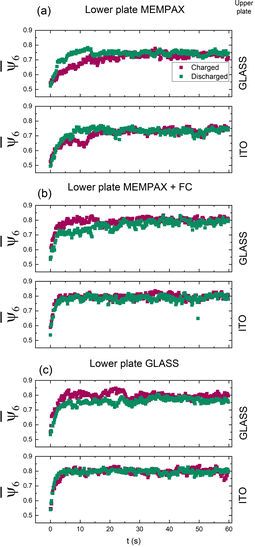
Fig. 8a shows the value of the average of the sixth orientational order parameter of the final particle configurations of the different combinations of plates after 60 s are displayed. It can be inferred that less-ordered stable crystal structures can be assembled on the MEMPAX substrate, while on the strong tribocharged fluorocarbon-coated substrate, a similar ordering is reached as for a glass substrate. However, in the fluorocarbon case, the charging from the top plate counteracts the charging of the bead with the bottom plate (cf.Table 1), such that the charging effect is negligible and the system can reach an ordered state. On the other hand, the data suggests that on MEMPAX, the charging inhibits the formation of ordered crystals, as a lower sixth orientational order parameter value was obtained. Fig. 8(b) supports this charging mechanism, as it can be readily observed that the ordering deteriorates as the number of cycles without discharging (using an ioniser in Fig. 9) the system is increased. Before proceeding with the next cycle, we disorder the beads again by stirring them. Thus, the history of the experiment affects the tribocharging51 and, concurrently, the order in the system. These results demonstrate that when the charging is too pronounced, the effective pressure created by the upper plate is insufficient to promote the ordering of the beads, as the beads become immobile due to the electrostatic interactions with the plate. Regarding the MEMPAX substrate, we should mention that recently, Jimidar et al.17 showed that 10 μm PMMA beads were also less ordered on MEMPAX substrate after rubbing dry powder. They attributed this to the stiffness of the substrate. Still, it remains an open question to be investigated, as also the surface interaction forces, e.g., contact mechanics, are more dominant in the case of the 10 μm polymer beads than our mm-sized polystyrene beads studied here.13
As the history of the system seems to affect the final order in the system, we studied the effect of residual charge, as can be observed from the data in Fig. 8c. First, we carried out experiments using initial uncharged particles and plates. For the discharging step, we used a Nutri-Tech System™—Carico air purification system with an ionisation stage; it reduced the spheres and plates’ charge almost entirely, see Fig. 9.
To further support that charging aids the stabilisation of formed crystals, we performed experiments using steel balls. In this case, we used steel particles with a remanent magnetization in the same container used in our experiments. Crystallization was not observed even though we used the same condition as the polystyrene beads between glass–glass plates. However, we can observe from [STEEL BALLS] movies in the ESI† that the configurations do not reach a minimum of energy due to the lack of an effective stabilization mechanism. When particles collide, they undergo elastic collisions and acquire enough energy to separate other particles that otherwise would form linear structures. Particle configurations form gaslike states. When order is reached, in a larger container, there is no stabilisation mechanism present to preserve it, see video [STEEL BALLS big plate] in ESI.† In this case, the effects of magnetization are more effective, and linear assembly is more evident than in the smaller container. The general structure evolves to be ordered. The reordering is slow, and even at the end, the structure is not stabilized.
It can be readily observed that, in the experiments we have described, the bottom plate material and residual charge obtained after one experiment of charged/discharged particles only has a small influence, albeit slightly better in the charged case, on the final order of a particle configuration. Seemingly, for most cases, regardless of the charged/discharged state of the beads, similar dynamics were observed when the ITO plate was used as the top plate. This suggests that as the ITO substrate is conductive, the charge beads intrinsically lose some of their charge, not affecting the formation of crystal structures.
Fig. 10 shows that, in the beginning, the system's behaviour differs depending on whether the discharge is used, see videos [L-charged R-discharged G–G] and [L-charged R-discharged M–G]. In the cases where the lower plate is glass Fig. 10(c), the differences between the initial charged and discharged state are small; however, when the lower plate is MEMPAX or MEMPAX + FC, Fig. 10(a) and (b), respectively, this difference is more pronounced, corroborating the strong tribocharging properties of the MEMPAX and fluorocarbon surfaces. After ≈20 s, the initial charge/discharge role had no significant effect as the system possibly reached a saturated charged state.
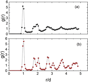 | ||
| Fig. 11 g(r) curves of the vibrated polystyrene beads in which the (a) glass-like state and (b) crystalline state can be observed. | ||
4. Conclusions and final remarks
We have studied the transition from an amorphous particle configuration to crystal ordering in a granular two-dimensional system between two plates, one fixed and the other that is free to move across the system. The system is under acoustic vibration, and we have investigated the effect of the frequency of the vibration, the number of particles in the system and the material properties of the plates on the attained crystal ordering in the system.Crystallisation is achieved through a combination of fluidisation created by the vibration of the system and the effective pressure created by the upper plate, from outside to inside of the plate, which lets particles find the minima of energy configurations. We found that the oscillatory motion of the upper plate around its centre creates an effective pressure over the ensemble, and particles are pushed toward the centre of the plate. This effective pressure acts independently of the charge of the particles.
By continuously rolling and hitting the particles with the plates, particles acquire electric charges and tend to stick to one of the plates. When a crystal, an ordered particle configuration, is reached, it is stabilised because of the electric interaction between particles and the material plates. Thus, the results corroborate that electrostatic interaction between the beads and the plates appears to play a significant role for a stabilised crystal configuration. In the absence of these forces, for instance, when steel beads are used, the order in the particle configurations is more challenging to reach, see video [STEEL BALLS small plate] in ESI.† This highlights the need for some particle charge to stabilise the ordered particle configuration. However, when electric particle-plate surface interactions are stronger, crystallisation order can be lowered in some cases, as was observed on the MEMPAX plate.
Our work opens a new research avenue on driven crystallisation using “kicks of pressure” stabilised by electric charges. Different particle materials can be used in different plate combinations (plastic plates), and the method could be extended to work with microspherical and colloidal particles in the future. In addition, the assembly of such beads or colloids can also be studied in electrolyte solutions,52 understanding the effect of electrostatic interactions on the assembled crystals, with a stronger focus on solid–liquid contact electrification phenomena.
Author contributions
F. D. and I. S. M. J. conceived and developed the experimental system, A. G. J.-D. and F. D. performed the experiments, F. D. and I. S. M. J. analysed and discussed the results. The three authors participated in the preparation of the manuscript. All authors reviewed the manuscript.Data availability
The data supporting this article have been included as part of the ESI.†Conflicts of interest
There are no conflicts to declare.Acknowledgements
The authors gratefully acknowledge financial support from CONACyT, Mexico, through Grant No. 731759 (Ciencia de Frontera 2019). A. G. J.-D. acknowledges the scholar fellowship from CONAHCyT, México: CVU 1332816 (2024). I. S. M. J. gratefully acknowledges funding from the Methusalem grant (METH7) and financial support (OZR4311) from the VUB and thanks Kai Sotthewes for fruitful discussions.References
- B. Li, D. Zhou and Y. Han, Nat. Rev. Mater., 2016, 1, 1–13 Search PubMed.
- J. Schockmel, E. Mersch, N. Vandewalle and G. Lumay, Phys. Rev. E: Stat., Nonlinear, Soft Matter Phys., 2013, 87, 062201 CrossRef CAS PubMed.
- J. S. Olafsen and J. S. Urbach, Phys. Rev. Lett., 1998, 81, 4369 CrossRef CAS.
- J. Kosterlitz and D. J. Thouless, Prog. Low Temp. Phys., 1978, 7, 371–433 Search PubMed.
- D. R. Nelson and B. Halperin, Phys. Rev. B: Condens. Matter Mater. Phys., 1979, 19, 2457 CrossRef CAS.
- F. López-González, A. M. Herrera-González and F. Donado, Phys. A, 2022, 590, 126756 CrossRef.
- F. López-González, F. Pacheco-Vázquez and F. Donado, Phys. A, 2023, 620, 128768 CrossRef.
- D. A. Morales-Barrera, G. Rodríguez-Gattorno and O. Carvente, Phys. Rev. Lett., 2018, 121, 074302 CrossRef CAS PubMed.
- Z. Zhang, Y. Wang, I. S. Jimidar and X. Ye, Int. J. Multiphase Flow, 2024, 179, 104907 CrossRef CAS.
- I. S. Jimidar, K. Sotthewes, H. Gardeniers, G. Desmet and D. van der Meer, Soft Matter, 2022, 18, 3660–3677 RSC.
- N. Preud'Homme, G. Lumay, N. Vandewalle and E. Opsomer, Phys. Rev. E, 2021, 104, 064901 CrossRef PubMed.
- S. Luding and J. Tomas, Granular Matter, 2014, 16, 279–280 CrossRef.
- K. Sotthewes and I. S. Jimidar, Small, 2024, 2405410 CrossRef PubMed.
- K. Sotthewes, G. Roozendaal, A. SÌŒutka and I. S. Jimidar, ACS Appl. Mater. Interfaces, 2024, 16, 12007–12017 CrossRef CAS PubMed.
- I. S. Jimidar, K. Sotthewes, H. Gardeniers and G. Desmet, Langmuir, 2020, 36, 6793–6800 CrossRef CAS PubMed.
- C. Park, T. Lee, Y. Xia, T. J. Shin, J. Myoung and U. Jeong, Adv. Mater., 2014, 26, 4633–4638 CrossRef CAS PubMed.
- I. Jimidar, M. de Waard, G. Roozendaal and K. Sotthewes, Soft Matter, 2024 10.1039/D4SM01196A.
- W. Van Geite, I. S. Jimidar, K. Sotthewes, H. Gardeniers and G. Desmet, Mater. Des., 2022, 216, 110573 CrossRef CAS.
- M. X. Lim, B. VanSaders, A. Souslov and H. M. Jaeger, Phys. Rev. X, 2022, 12, 021017 CAS.
- M. X. Lim and H. M. Jaeger, Phys. Rev. Res., 2023, 5, 013116 CrossRef CAS.
- C. O. Solano-Cabrera, P. Castro-Villareal, R. E. Moctezuma, F. Donado, J. C. Conrad and R. Castañeda-Priego, Ann. Rev. Condens. Matter Phys., 2025, 16 DOI:10.1146/annurev-conmatphys-041124-120513.
- R. Cademartiri, C. A. Stan, V. M. Tran, E. Wu, L. Friar, D. Vulis, L. W. Clark, S. Tricard and G. M. Whitesides, Soft Matter, 2012, 8, 9771–9791 RSC.
- S. Battat, A. A. Nagarkar, F. Spaepen, D. A. Weitz and G. M. Whitesides, Phys. Rev. Mater., 2023, 7, L040401 CrossRef CAS.
- S. Battat, D. A. Weitz and G. M. Whitesides, Soft Matter, 2023, 19, 3190–3198 RSC.
- A. Prevost, P. Melby, D. A. Egolf and J. S. Urbach, Phys. Rev. E: Stat., Nonlinear, Soft Matter Phys., 2004, 70, 050301 CrossRef PubMed.
- P. Melby, F. V. Reyes, A. Prevost, R. Robertson, P. Kumar, D. A. Egolf and J. S. Urbach, J. Phys.: Condens. Matter, 2005, 17, S2689 CrossRef CAS.
- J. Olafsen and J. Urbach, Phys. Rev. Lett., 2005, 95, 098002 CrossRef CAS PubMed.
- A. N. Kurariya and F. Barthelat, PNAS, 2022, 120, e2215508120 CrossRef PubMed.
- M. Mirkhalaf, T. Zhou and F. Barthelat, PNAS, 2018, 115, 9128–9133 CrossRef CAS PubMed.
- A. Bahmani, J. W. Pro and F. Barthelat, Appl. Mater. Today, 2022, 29, 101601 CrossRef.
- A. C. Lapadatu and H. Jakobsen, Handbook of Silicon Based MEMS Materials and Technologies, Elsevier, 2015, pp. 599–610 Search PubMed.
- S. Dorbolo, D. Volfson, L. Tsimring and A. Kudrolli, Phys. Rev. Lett., 2005, 95, 044101 CrossRef CAS PubMed.
- R. Fuchs, J. Meyer, T. Staedler and X. Jiang, Tribol.-Mater., Surf. Interfaces, 2013, 7, 103–107 CrossRef CAS.
- D. J. Lacks and T. Shinbrot, Nat. Rev. Chem., 2019, 3, 465–476 CrossRef CAS.
- K. Sotthewes, H. J. Gardeniers, G. Desmet and I. S. Jimidar, ACS Omega, 2022, 7, 41828–41839 CrossRef CAS PubMed.
- N. Mujica and S. Waitukaitis, Phys. Rev. E, 2023, 107, 034901 CrossRef CAS PubMed.
- A. Schella, S. Herminghaus and M. Schröter, Soft Matter, 2017, 13, 394–401 RSC.
- J. M. Harper, C. S. McDonald, E. J. Rheingold, L. C. Wehn, R. E. Bumbaugh, E. J. Cope, L. E. Lindberg, J. Pham, Y.-H. Kim and J. Dufek, et al. , Matter, 2024, 7, 266–283 CrossRef.
- N. Preudhomme, G. Lumay, N. Vandewalle and E. Opsomer, Soft Matter, 2023, 19, 8911–8918 RSC.
- M. R. Swift and M. I. Smith, Soft Matter, 2024, 20, 7038–7043 RSC.
- C. A. Schneider, W. S. Rasband and K. W. Eliceiri, Nat. Methods, 2012, 9, 671–675 CrossRef CAS PubMed.
- M. Ledesma-Motolinía, J. L. Carrillo-Estrada and F. Donado, Sci. Rep., 2021, 11, 16531 CrossRef PubMed.
- G. L. Hunter and E. R. Weeks, Rep. Prog. Phys., 2012, 75, 066501 CrossRef PubMed.
- H. J. Schope, G. Bryant and W. van Megen, J. Chem. Phys., 2007, 127, 084505 CrossRef PubMed.
- A. Mughal, H. K. Chan, D. Weaire and S. Hutzler, Phys. Rev. E, 2012, 85, 051305 CrossRef CAS PubMed.
- I. Castillo, F. J. Kampas and J. D. Pintér, Eur. J. Oper. Res., 2008, 191, 786–802 CrossRef.
- R. L. Graham, B. D. Lubachevsky, K. J. Nurmela and P. R. J. Ostergard, Discrete Math., 1998, 181, 139–154 CrossRef.
- N. Mladenovic, F. Plastriac and D. Urosevic, Reformulation descent applied to circle packing problems, Comput. Oper. Res., 2005, 32, 2419 CrossRef.
- P. Szabó, T. Csendes, L. Casado and I. G. García, Optimization Theory, Kluwer Academic, Netherlands, 2001, pp. 191–206 Search PubMed.
- I. S. Jimidar, W. Kwiecinski, G. Roozendaal, E. S. Kooij, H. J. Gardeniers, G. Desmet and K. Sotthewes, ACS Appl. Mater. Interfaces, 2023, 15, 42004–42014 CrossRef CAS PubMed.
- G. Grosjean and S. Waitukaitis, Phys. Rev. Lett., 2023, 130, 098202 CrossRef CAS PubMed.
- P. Karnchanaphanurach, B. Lin and S. A. Rice, Phys. Rev. E, 2000, 61, 4036 CrossRef CAS PubMed.
Footnote |
| † Electronic supplementary information (ESI) available: Experimental videos and additional graphs. See DOI: https://doi.org/10.1039/d4sm01017e |
| This journal is © The Royal Society of Chemistry 2024 |

