Conductive gradient hydrogels allow spatial control of adult stem cell fate†
Shang
Song
ade,
Kelly W.
McConnell
 a,
Dingying
Shan
a,
Cheng
Chen
b,
Byeongtaek
Oh
a,
Jindi
Sun
d,
Ada S. Y.
Poon
b and
Paul M.
George
a,
Dingying
Shan
a,
Cheng
Chen
b,
Byeongtaek
Oh
a,
Jindi
Sun
d,
Ada S. Y.
Poon
b and
Paul M.
George
 *ac
*ac
aDepartment of Neurology and Neurological Sciences, Stanford University, School of Medicine, 300 Pasteur Dr, MC5778 Stanford Stroke Center, Stanford, CA 94305-5778, USA. E-mail: pgeorge1@stanford.edu; Tel: +1 (650) 725-0013
bDepartment of Electrical Engineering, Stanford University, Stanford, CA, USA
cStanford Stroke Center and Stanford University School of Medicine, Stanford, CA, USA
dDepartment of Biomedical Engineering, The University of Arizona, Tucson, AZ, USA
eDepartments of Neuroscience GIDP, Materials Science and Engineering, BIO5 Institute, The University of Arizona, Tucson, AZ, USA
First published on 25th January 2024
Abstract
Electrical gradients are fundamental to physiological processes including cell migration, tissue formation, organ development, and response to injury and regeneration. Current electrical modulation of cells is primarily studied under a uniform electrical field. Here we demonstrate the fabrication of conductive gradient hydrogels (CGGs) that display mechanical properties and varying local electrical gradients mimicking physiological conditions. The electrically-stimulated CGGs enhanced human mesenchymal stem cell (hMSC) viability and attachment. Cells on CGGs under electrical stimulation showed a high expression of neural progenitor markers such as Nestin, GFAP, and Sox2. More importantly, CGGs showed cell differentiation toward oligodendrocyte lineage (Oligo2) in the center of the scaffold where the electric field was uniform with a greater intensity, while cells preferred neuronal lineage (NeuN) on the edge of the scaffold on a varying electric field at lower magnitude. Our data suggest that CGGs can serve as a useful platform to study the effects of electrical gradients on stem cells and potentially provide insights on developing new neural engineering applications.
1. Introduction
The microenvironment in which cells reside and interact provides complex physicochemical cues to drive dynamic cellular processes and behaviors.1–3 By harnessing this native machinery, the use of electrical stimulation has gained tremendous interest to modulate cellular activity and restore functions for biological and clinical applications. A wide range of stimulation conditions and cell types have been explored for cell proliferation, differentiation, directed migration, calcium signaling, ion channel densities, and neurotrophic factor changes.4–12 However, many of these studies solely focus on using a uniform electric field to probe cellular responses. It is worth noting that the variation of gradients, namely electrical gradients, directly contributes to the spatial patterning, development, and regeneration of human tissues and organs.13–15 Therefore, studying the variation in the electrical field strength and its cellular interaction may prove beneficial to understanding many intrinsic biological processes and create potential regenerative strategies for tissue repair.Conductive hydrogels consist of a network matrix made of entangled polymers with electrically conductive fillers to exhibit high mechanical flexibility and electrical conductivity.16 They are constructed in 3D structure with the ability to maintain high water content, porosity, softness, and mechanical integrity.17,18 The physical properties of conductive hydrogels to the native tissue extracellular matrix (ECM) which is primarily composed of water and biomolecules make them the ideal candidate to mimic the natural cellular environment. In addition, conductive hydrogels can be electrically stimulated which can be highly relevant and desirable in mimicking electrical activities for neural engineering applications.19,20 Developing new interactive conductive hydrogels that display gradual changes in electrical field strength is highly desirable to study the cellular response in a more physiological relevant manner.
In this study, we have developed conductive gradient hydrogels (CGGs) to investigate the effect of electrical gradients on neural differentiation of human mesenchymal stem cells (hMSCs). CGGs were porous and viscoelastic in nature which was ideal for cellular attachment. Importantly, they exhibited a uniform electric field in the center while displaying a varying electric field on the edge. Our results showed that applying an electrical field enhances hMSC viability and adhesion, but more importantly, the electrical field causes a distinct shift in cell differentiation. Our novel CGGs allow us not only to understand cellular behavior in a non-uniform electrical field mimicking the physiological environment, but also provide a deeper understanding on electrical modulation of cell development and functions.
2. Materials and Methods
Fabrication of the gradient gel
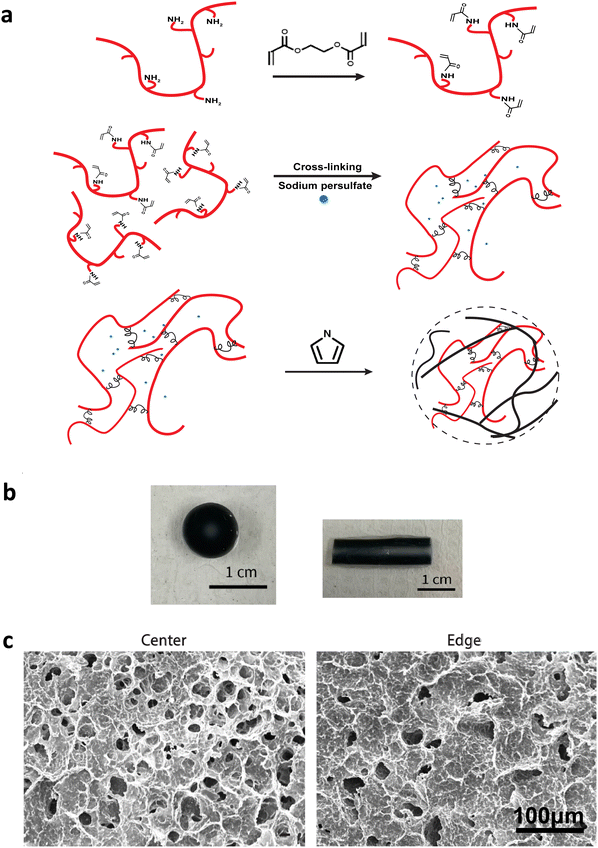
A final 2 wt% gelatin and 10 wt% poly(ethylene glycol) diacrylate (437441, Sigma) in Phosphate Buffered Saline (PBS) were mixed for 2 hours at 65 °C. The mixture was added with 10% potassium persulfate and casted into a cylindrical mold. After the mixture solidified into a gel, it was rinsed with DI water for 5 minutes. Subsequently, it was immersed in a 33 vol% solution of Pyrrole (AC157710250, Fisher) in Ethanol for 10 minutes. This step enabled the monomers to gradually infiltrate the gel matrix, creating a gradient effect, and to polymerize into polypyrrole with potassium persulfate as the oxidant. The gel was then extracted and thoroughly washed in DI water for at least an overnight period before being used. The radial-gradient conductive gel with varying concentration of polypyrrole was formed (Fig. 1). The conductive gradient gel was cut into small disks with 3 mm in thickness and 9 mm in diameter (Fig. 1b, left). All conductive gradient disks were washed extensively and sterilized prior to use. Blank gels were formed similarly without pyrrole.Mass balance modeling
The following assumptions were made to solve the numerical solution that described the radial diffusion of polypyrrole into the gel based on the principle of mass balance: (1) the volumetric flow rate k was constant; (2) the total gel volume remained constant; (3) the uptake of pyrrole into the gel was instantaneous, which was evidenced by the porosity change. Mass balance was described as: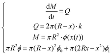 | (1) |
 | (2) |
Rheological characterization
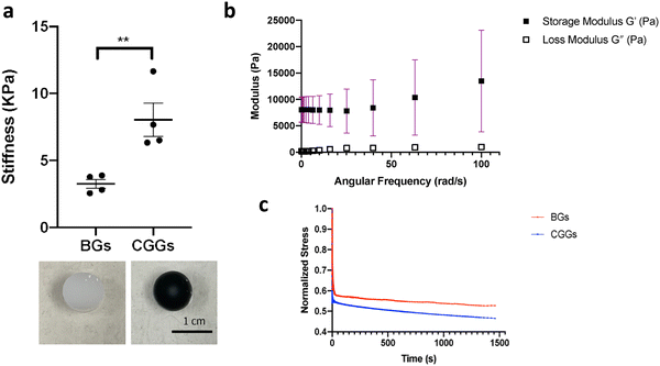
Dynamic oscillatory rheology experiments were performed on a stress-controlled rheometer (AR-G2, TA instrument) using an 8-mm diameter cone-plate geometry. Disks were loaded onto the rheometer and a humidity chamber was secured in place to prevent dehydration. Frequency sweeps from 0.1–100% S−1 at 23 °C were performed at 5% constant strain to obtain storage moduli (G′) and loss moduli (G′′) and stress relaxation was quantified under constant strain (Fig. 2).Conductivity measurement
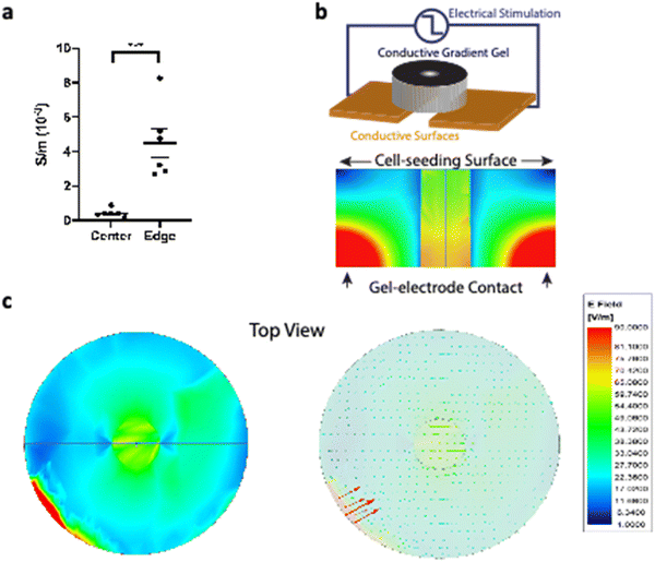
The conductive gradient gels were immersed and thoroughly washed in deionized (DI) water to eliminate ionic charges. They were longitudinally cut into thin slices which provided greater surface area for conductivity measurement. The experimental conductivity was measured using the direct current (d.c.) four-point probe method with a Keithley 2400 Source Meter 45 at room temperature (Fig. 3a). Physical dimensions of scaffolds were measured by a caliper. The center region diameter was 2 mm, while anything outside of the center region was considered to be the edge area up to the entire disk diameter (which is 9 mm).Electromagnetic finite element method (FEM) simulation
Electromagnetic field computation was conducted with physical dimensions and electrical properties based on experimental conductivity as previously described1 (Fig. 3b and c). Briefly, electromagnetic simulations were conducted on ANSYS HFSS with the finite element method (FEM) solver, which was based on the model that subdivided into many small subsections in the form of tetrahedra. A solution was found such that the interrelated fields within these tetrahedra satisfied the Maxwell's Equations across inter-element boundaries. Specifically, the electric field E is solved using the equationwhere
 , and εr, μr are the relative permittivity and permeability respectively. This equation makes no approximation from Maxwell's Equations, thus accurately capturing the electromagnetic field within the model. At each iterative calculation, the fields and associated S-matrix was generated, with the next iteration minimizing the field errors with an adaptive mesh refinement process. A solution was found when ΔSmax is smaller than the target, which is set to be 0.05% for high precision.
Cell culture
Human bone marrow derived MSCs (70022, Stemcell Technologies) were first expanded under 10% Fetal Bovine Serum (FBS) (Sigma) and 1% penicillin/streptomycin (P/S) (Fisher) in DMEM/F12 medium (Thermo Fisher Scientific). For all experiments, hMSC-seeded scaffolds were maintained under basal medium condition consisting of 2% B27 supplement (17504044, Thermo Fisher Scientific) in the neurobasal media (21103049, Thermo Fisher Scientific).Electrically-stimulation of hMSC-seeded conductive gradient scaffolds
About 25![[thin space (1/6-em)]](https://www.rsc.org/images/entities/char_2009.gif) 000 cells in medium suspension were seeded directly on top of the conductive gradient scaffolds. After the initial cell seeding, electrical stimulation (±500 mV at 20 Hz) was applied through the conductive platform where desired electrical fields were created on the scaffold. After cell seeding on day 0, cell-seeded scaffolds were exposed to electrical fields on day 1, 3, 5 and analyzed on day 6.
000 cells in medium suspension were seeded directly on top of the conductive gradient scaffolds. After the initial cell seeding, electrical stimulation (±500 mV at 20 Hz) was applied through the conductive platform where desired electrical fields were created on the scaffold. After cell seeding on day 0, cell-seeded scaffolds were exposed to electrical fields on day 1, 3, 5 and analyzed on day 6.
Cell viability and adhesion
A viability kit (L3224, Thermo Fisher Scientific) was used per the manufacturer's protocol. The samples were incubated with 2 μL mL−1 of ethidiumhomodimer-1 and calcein AM for about 15 min at 37 °C in the dark. They were then rinsed with 1× PBS and imaged under the Keyence BZ-X710 microscope. The alive and dead cells on the conductive scaffold were quantified for viability and adhesion analysis.Immunofluorescence staining
Samples were fixed with 4% formaldehyde followed by PBS washes. They were permeabilized with 0.1% Triton X-100 for 10![[thin space (1/6-em)]](https://www.rsc.org/images/entities/char_2009.gif) min and incubated in blocking solution (PBS, 1% normal goat serum) for 30
min and incubated in blocking solution (PBS, 1% normal goat serum) for 30![[thin space (1/6-em)]](https://www.rsc.org/images/entities/char_2009.gif) min. They were first incubated with primary antibodies (PAX6
min. They were first incubated with primary antibodies (PAX6![[thin space (1/6-em)]](https://www.rsc.org/images/entities/char_2009.gif) :
:![[thin space (1/6-em)]](https://www.rsc.org/images/entities/char_2009.gif) 42-6600, SOX1: AF3369, SOX2: AF2018, Nestin: ABD69MI from Fisher Scientific; Tuj-1: CH23005, Neuromics; NeuN: 12943S, Cell Signaling Tech.; GFAP: AB5804, EMD Millipore; Olig2: AB109186, Abcam) at a dilution of 1
42-6600, SOX1: AF3369, SOX2: AF2018, Nestin: ABD69MI from Fisher Scientific; Tuj-1: CH23005, Neuromics; NeuN: 12943S, Cell Signaling Tech.; GFAP: AB5804, EMD Millipore; Olig2: AB109186, Abcam) at a dilution of 1![[thin space (1/6-em)]](https://www.rsc.org/images/entities/char_2009.gif) :
:![[thin space (1/6-em)]](https://www.rsc.org/images/entities/char_2009.gif) 100–1
100–1![[thin space (1/6-em)]](https://www.rsc.org/images/entities/char_2009.gif) :
:![[thin space (1/6-em)]](https://www.rsc.org/images/entities/char_2009.gif) 300 for 1
300 for 1 ![[thin space (1/6-em)]](https://www.rsc.org/images/entities/char_2009.gif) h and washed twice for 5
h and washed twice for 5![[thin space (1/6-em)]](https://www.rsc.org/images/entities/char_2009.gif) min with PBS to remove residues. They were then incubated with secondary antibodies (Thermo Fisher Scientific) at a dilution of 1
min with PBS to remove residues. They were then incubated with secondary antibodies (Thermo Fisher Scientific) at a dilution of 1![[thin space (1/6-em)]](https://www.rsc.org/images/entities/char_2009.gif) :
:![[thin space (1/6-em)]](https://www.rsc.org/images/entities/char_2009.gif) 1000 for 1
1000 for 1 ![[thin space (1/6-em)]](https://www.rsc.org/images/entities/char_2009.gif) h, followed by PBS washes for 5
h, followed by PBS washes for 5![[thin space (1/6-em)]](https://www.rsc.org/images/entities/char_2009.gif) min. DAPI (1
min. DAPI (1![[thin space (1/6-em)]](https://www.rsc.org/images/entities/char_2009.gif) :
:![[thin space (1/6-em)]](https://www.rsc.org/images/entities/char_2009.gif) 1000, D9542, Sigma-Aldrich) was added for nuclear staining. Images were obtained using a Keyence BZ-X710 microscope equipped with full BZ acquisition and analysis software.
1000, D9542, Sigma-Aldrich) was added for nuclear staining. Images were obtained using a Keyence BZ-X710 microscope equipped with full BZ acquisition and analysis software.
Circularity test
To find the circularity, ten random cells were chosen per sample, and the analyzer was blinded to sample condition. The Nestin and DAPI channels were separated and thresholded to isolate the cell area from the background. The circularity was measured using ImageJ, where circularity = 4pi(area/perimeter^2).Statistical analysis
All quantifications were performed by a blinded individual. Samples were analyzed using the Student's t-test or one-way analysis of variance (ANOVA) followed by Tukey and multiple comparisons using GraphPad Prism software (San Diego, CA). A p value of < 0.05 was accepted as statistically significant for all analyses. Data are presented as mean ± SE.3. Results and discussion
Physical and electrical characterizations of CGGs
The CGGs were made of a crosslinked network of gelatin and poly(ethylene glycol) diacrylate in which a radial distribution of polypyrrole was developed (Fig. 1a). Briefly, the pre-formed hydrogels were immersed in the pyrrole solution in which the hydrogel conductivity was achieved by post-polymerization of conductive polymer. Because pyrrole monomers diffused from the outermost to innermost of hydrogel network to polymerize in a concentration-driven and time-dependent manner, polypyrrole was formed with the highest concentration on the edge while the lowest amount in the center of the hydrogel (Fig. 1b). The porosity of hydrogel was greatly reduced on the edge compared to the center due to radial polymerization of polypyrrole (Fig. 1c). A mass balance modeling was applied to study the gel porosity. Numerical solution (eqn (1) and (2)) was obtained as an average gel porosity versus time immersed in polypyrrole solution in Fig. S1 (ESI†). In the beginning, the average gel porosity was equal to the initial porosity ϕ0 = 0.1178 based on scanning electron microscopy images (Fig. 1c). After t = 5 min in polypyrrole solution, the edge of blank gel was shown with radially diffused polypyrrole at a distance of x = 1.75 mm into the gel and the average porosity decreased to ϕ = 0.0603 (Fig. 2b). At t = 10 min, the average porosity reached to a value of 0.035 (Fig. 2c), which matched the experimental observation in Fig. 1b (x = 3.5 mm). Based on the numerical simulation, a blank gel scaffold was expected to have fully absorbed polypyrrole at t = 11.42 min, where the maximum absorption would be expected (x = R) and the average porosity would reach its minimum value at ϕ1 = 0.0336.The mechanical characterization of CGGs showed a high compliance and degree of stress relaxation. The bulk stiffness of CGGs was 8.9 ± 4.0 kPa, which was significantly higher than 3.3 ± 1.6 kPa of blank gels (BGs) without polypyrrole (Fig. 2a). The addition of polypyrrole significantly increased the bulk gel strength. The CGGs also exhibited viscoelastic behavior as shown by the higher storage modulus compared to loss modulus (Fig. 2b). The increased stress relaxation in CGGs suggests that the addition of polypyrrole contributes to the viscoelastic nature of these gels (Fig. 2b and c).
CGGs further demonstrated a conductive gradient because of differential formation of polypyrrole in the center compared to the edge of the hydrogels. The edge of CGGs showed significantly higher conductivity of 4.5 ± 1.8 × 10⁻³ S m−1 compared to the center 0.43 ± 0.17 × 10⁻³ S m−1 of CGGs (Fig. 3a). These gels were placed on a stimulating platform where electrical stimulation could be applied through conductive gel-electrode contact areas (Fig. 3b). Based on measured conductivities of CGGs, the electromagnetic finite element method (FEM) simulation showed that electric field strength was the highest at the gel-electrode contact areas and gradually decreased inside the CGGs (Fig. 3b). With a closer inspection on the cell-seeding surface of CGGs, a uniform electric field of 54–56 V m−1 was observed in the center compared to a varying field strength of 1–22 V m−1 present at the edge of CGGs when stimulating at ± 500 mV at 20 Hz (Fig. 3c). We optimized electrical stimulation parameters based on our lab's previous work. A voltage of −500 mV was determined to provide the optimal electrical field (54–56 V m−1) to support optimal cell functions as demonstrated by our previous manuscripts.4,22 A frequency of 20 Hz was chosen as it ensures stable conductivity through the hydrogel but not PBS (ionic conductivity).19
Cellular response on electrically-stimulated CGGs
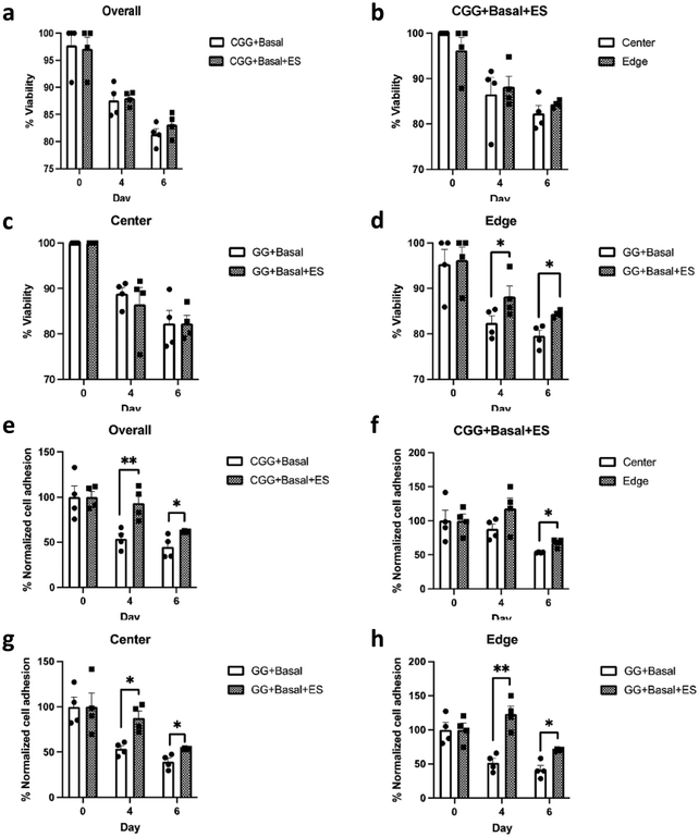
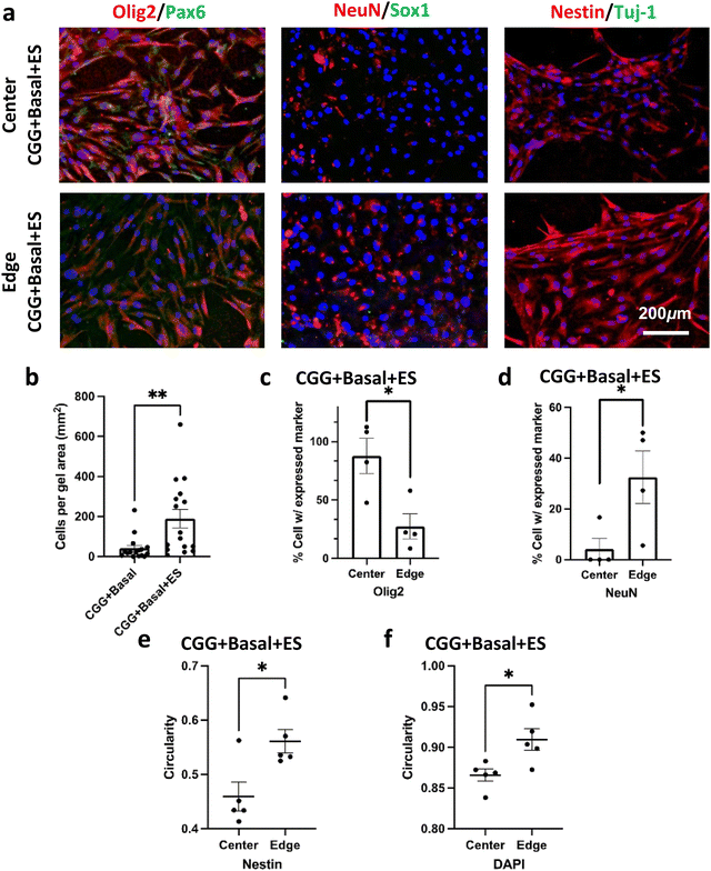
Cells were maintained in the basal medium condition (Basal) to exclude any potential chemical effects on proliferation and induction (see Section 2. Materials and Methods). HMSCs were seeded on CGGs and received electrical stimulation on day 1, 3, and 5. Both unstimulated and stimulated conditions showed a high cell viability on day 6 at 81.3 ± 1.02% (CGG + Basal) and 83.1 ± 1.09% (CGG + Basal + ES), respectively (Fig. 4a–d and Fig. S2, ESI†). However, when comparing regionally, there was a slight enhancement in cell viability at the edge of stimulated CGGs than that of unstimulated on day 4 and 6 (Fig. 4d). Beginning on day 4, a significant reduction in the number of cells adhered on the edge of CGGs under the unstimulated condition (Fig. 4e–h). Specifically, the electrically-stimulated CGGs showed better overall cellular adhesion than the unstimulated condition at 93.1 ± 9.02% and 53.9 ± 5.59% respectively on day 4 and at 61.7 ± 0.48% and 44.8 ± 6.26% respectively on day 6 (Fig. 4e). The trend showing improved cell adhesion was consistent across the center and edge of the CGGs under electrical influence (Fig. 4g–h). These data suggest that electrical stimulation significantly enhances cell attachment to CGGs without decreasing cell viability.Electrical stimulation has shown to induce several transcription factors that are involved in cell self-renewal and survival, cell differentiation, synaptic remodeling, neural regeneration.4–7,19,21–25 We hypothesized that the electrical stimulation and electrical gradient would influence differentiation changes and properties of the hMSCs. The unstimulated condition (CGG + Basal) showed fewer stained cells on the surface due to the lack of cellular attachment as described above (Fig. 4e and 5b). Therefore, it was statistically unreasonable to compare the stained markers between the unstimulated and stimulated groups. With a closer inspection of the stimulated condition, we observed that hMSCs displayed a high level of neural progenitor cell markers such as Nestin, glial fibrillary acidic protein (GFAP), Sox2, and a limited amount of Sox 1 (Fig. 5 and Fig. S3, S4, ESI†). Interestingly, due to the present electrical gradient in CGGs, there was a bias in cell fate decision: oligodendrocyte transcription factor (Oligo2) was highly expressed at the center whereas NeuN was more detectable at the edge of CGGs (Fig. 5a, c and d). A uniform electrical field with greater intensity shifted hMSC differentiation toward oligodendrocyte lineage, while cells on a varying electrical field at lower magnitude preferred neuronal lineage. A cell circularity study from Nestin- and DAPI staining showed that hMSCs were more rounded on the edge than the center of CGGs (Fig. 5a, e and f). Our findings suggest that by varying electrical field, cells not only change their shapes, but also biasing cell fate toward a particular lineage which is difficult to study under a uniform electrical field.
3. Discussion
In this study, we created CGGs with an electrical field gradient of 54–56 V m−1 in the center and a varying field strength of 1–22 V m−1 at the edge (Fig. 3). This electrical field gradient was chosen because it mimics the electro-physiological conditions and offers electrical biases in which distinct cellular response could be studied correspondingly.26,27 The CGGs supported hMSCs with electrical stimulation improving cellular adhesion. Stronger electric fields showed differentiation of hMSCs towards oligodendrocyte lineage while hMSCs exposed to the lower electric fields with varying strengths demonstrated neuronal markers. This new CGG allows for differentiation of multiple cell types upon a single polymeric platform to study cellular interactions and responses to non-uniform electric fields.Electrical gradients are essential in regulating biological functions and pathophysiological diseases, such as stem cell migration along the rostral migratory stream (RMS) within the olfactory bulb,26 embryonic development and morphogenesis,29,30 directing nerve orientation,30,31 wound healing,32,33 and angiogenesis and movement of metastatic cancer cells.34,35 The strength of endogenous electric fields in intact mammalian tissues is generally 3–5 V m−1 and can increase up to 10–20 V m−1 after injury.28,36,37 Our previous findings have described using an unform electric field (∼40–55 V m−1) to promote changes in transcription factors that enhanced secretion of neurotrophic factors.4,22 Physical disruption of cell membranes and tissues causes ionic imbalance that is suspected to act as a signal for directed cell migration and growth toward the wound until the electrical field is restored.33,38 Injury induced electrical gradients were observed when comparing the normal cortical surface to a damaged cortex area in rat brains.27,39,40 Aging caused the potential difference in the brain to increase from 1–1.6 mV at 5 days to 20 mV of mature rats.27 Our conductive polymer platform creates the ability to study the effect of electrical gradients which may produce biological effects that would not be observed with uniform fields. While we have evaluated a specific stimulation paradigm based on prior work, our platform provides the opportunity to easily evaluate various waveforms and frequencies and their effect on the electrical gradient and cell function.
hMSCs shift their fates into adipogenic, myogenic, and osteogenic lineages based on surrounding ECM cues41–43 Electrical stimulation has been commonly studied for hMSC proliferation, migration, and primarily in osteogenic differentiation. A 200 μA of direct current caused hMSC migration in the polypyrrole incorporated polycaprolactone (PCL) scaffolds due to sensing in the voltage-gated ion channels.44 An electric field of ∼20 mV cm−1 on hMSCs enhanced expression of osteogenic differentiation markers and collagen deposition.45 The addition of pulsed electromagnetic field (4.5 ms bursts of 20 pulses and a repetitive rate of 15 Hz) is crucial for BMP-2 dependent osteoblastic differentiation.46 Similarly, pulsed electromagnetic field (pulse duration of 300 μs and a repetitive rate of 7.5 Hz) further increased alkaline phosphatase activity.47 hMSCs from several tissue sources have demonstrated promising potential in neural repair such as differentiation to a particular neural lineage,48 formation of functional neurons,49 and nerve regeneration after implantation.50 A previous study reported that hMSCs adopted a neuronal-like morphology at day 10 with neural markers such as noggin, MAP2, neurofilament, β tubulin III and Nestin on 3D polypyrrole-incorporated collagen-based fibers (electrical pulses of 1.2 V with pulse duration of 5 ms at a frequency of 200 Hz).51 A polypyrrole-alginate hydrogel, even without electrical stimulation, promoted hMSC growth and neural differentiation at 14 days (i.e. Tuj1 and MAP2).52 Our study showed that electrical stimulation enhanced cell viability and adhesion to the CGG surface (Fig. 4). Cells seeded in the center of CGGs that created a uniform electric field with high magnitude shifted toward oligodendrocyte lineage, whereas those at the edge of CGGs preferred neuronal lineage with varying field direction with a lower field strength (Fig. 5). This suggests that electrical gradient alone could impact cell viability, shape, and preferential differentiation. Compared to previous studies, one of the advantages of our CGGs is the preferential differentiation of hMSCs on the same scaffold without using chemical induction in a short period (<1 week). Furthermore, aside from the impact of electrical gradients, the mechanical aspects also play a critical role in influencing neural stem cell behaviors. By modifying the base polymer properties, this can be easily explored with our new platform.
4. Conclusions
In conclusion, CGGs represent a new form of conductive hydrogels with suitable tensile strength and material compliance for electrical modulation of hMSCs. Importantly, the varying electrical gradients displayed by CGGs enables preferential hMSC differentiation toward either oligodendrocyte or neuronal lineage without using chemical induction. CGGs serve as a useful tool for studying cellular behavior and functions related to non-uniform electric fields similar to those observed in physiologic conditions. They also present a platform for examining interactions across various cell types in both healthy and diseased states in vitro. A deeper understanding of cellular responses to varying electrical gradients is pivotal for unraveling biological pathways related to endogenous tissue development and regeneration and developing new neural engineering therapeutics.Conflicts of interest
The authors declare no competing financial interests.Acknowledgements
We would like to thank Yuxin Liu on measuring scaffold conductivity. This research was supported by the Eunice Kennedy Shriver National Institute of Child Health & Human Development (NICHD) of the National Institutes of Health (NIH) under Award Number F32HD098808 and the Technology and Research Initiative Fund (TRIF) from the University of Arizona (SS) and the Alliance for Regenerative Rehabilitation Research and Training (P2C HD08684) and NIH K08NS089976 and R01NS126761 (PMG).References
- A. Higuchi, Q. D. Ling, Y. Chang, S. T. Hsu and A. Umezawa, Chem. Rev., 2013, 113, 3297–3328 CrossRef CAS PubMed.
- F. Xing, L. Li, C. Zhou, C. Long, L. Wu, H. Lei, Q. Kong, Y. Fan, Z. Xiang and X. Zhang, Stem Cells Int, 2019, 2180925 CAS.
- X. Lin, Y. Shi, Y. Cao and W. Liu, Biomed. Mater., 2016, 11, 014109 CrossRef PubMed.
- S. Song, D. Amores, C. Chen, K. McConnell, B. Oh, A. Poon and P. M. George, Sci. Rep., 2019, 9, 19565 CrossRef CAS PubMed.
- B. Oh, A. Levinson, V. Lam, S. Song and P. George, J. Vis. Exp., 2018, 134, e57367 Search PubMed.
- S. Song and P. M. George, Neural Regener. Res., 2017, 12, 1976–1978 CrossRef CAS PubMed.
- P. M. George, T. M. Bliss, T. Hua, A. Lee, B. Oh, A. Levinson, S. Mehta, G. Sun and G. K. Steinberg, Biomaterials, 2017, 142, 31–40 CrossRef CAS PubMed.
- A. Guo, B. Song, B. Reid, Y. Gu, J. V. Forrester, C. A. B. Jahoda and M. Zhao, J. Invest. Dermatol., 2010, 130, 2320–2327 CrossRef CAS PubMed.
- M. J. McKasson, L. Huang and K. R. Robinson, Exp. Neurol., 2008, 211, 585–587 CrossRef PubMed.
- R. Nuccitelli, K. Lui, M. Kreis, B. Athos and P. Nuccitelli, Biochem. Biophys. Res. Commun., 2013, 435, 580–585 CrossRef CAS PubMed.
- J. G. Hardy, R. C. Sukhavasi, D. Aguilar, M. K. Villancio-Wolter, D. J. Mouser, S. A. Geissler, L. Nguy, J. K. Chow, D. L. Kaplan and C. E. Schmidt, J. Mater. Chem. B, 2015, 3, 8059–8064 RSC.
- B. Oh, Y. W. Wu, V. Swaminathan, V. Lam, J. Ding and P. M. George, Adv. Sci., 2021, 8, 2002112 CrossRef CAS PubMed.
- M. A. Lancaster, Dev. Cell, 2019, 48, 1–2 CrossRef CAS PubMed.
- F. Chang and N. Minc, Annu. Rev. Cell Dev. Biol., 2014, 30, 317–336 CrossRef CAS PubMed.
- M. Levin and C. G. Stevenson, Annu. Rev. Biomed. Eng., 2012, 14, 295–323 CrossRef CAS PubMed.
- M. Tomczykowa and M. E. Plonska-Brzezinska, Polymers, 2019, 11(2), 350 CrossRef PubMed.
- R. A. Green, R. T. Hassarati, J. A. Goding, S. Baek, N. H. Lovell, P. J. Martens and L. A. Poole-Warren, Macromol. Biosci., 2012, 12, 494–501 CrossRef CAS PubMed.
- A. Gelmi, M. K. Ljunggren, M. Rafat and E. W. H. Jager, J. Mater. Chem. B, 2014, 2, 3860–3867 RSC.
- S. Santhanam, V. R. Feig, K. W. McConnell, S. Song, E. E. Gardner, J. J. Patel, D. Shan, Z. Bao and P. M. George, Adv. Mater. Technol., 2023, 2201724 CrossRef CAS.
- V. R. Feig, S. Santhanam, K. W. McConnell, K. Liu, M. Azadian, L. G. Brunel, Z. Huang, H. Tran, P. M. George and Z. Bao, Adv. Mater. Technol., 2021, 6, 2100162 CrossRef CAS PubMed.
- S. Cohen-Cory and S. E. Fraser, Nature, 1995, 378, 192–196 CrossRef CAS PubMed.
- S. Song, K. W. McConnell, D. Amores, A. Levinson, H. Vogel, M. Quarta, T. A. Rando and P. M. George, Biomaterials, 2021, 275, 120982 CrossRef CAS PubMed.
- K.-A. Chang, J. W. Kim, J. A. Kim, S. Lee, S. Kim, W. H. Suh, H.-S. Kim, S. Kwon, S. J. Kim and Y.-H. Suh, PLoS One, 2011, 6, e18738 CrossRef CAS PubMed.
- B. Oh, S. Santhanam, M. Azadian, V. Swaminathan, A. G. Lee, K. W. McConnell, A. Levinson, S. Song, J. J. Patel, E. E. Gardner and P. M. George, Nat. Commun., 2022, 13, 1366 CrossRef CAS PubMed.
- B. Oh and P. M. George, Brain Res. Bull., 2019, 148, 10–17 CrossRef CAS PubMed.
- S. Song, D. Amores, C. Chen, K. W. McConnell, B. Oh, A. Poon and P. M. George, Sci. Rep., 2019, 9, 19565 CrossRef CAS PubMed.
- J. Bures, Electroencephalogr. Clin. Neurophysiol., 1957, 9, 121–130 CrossRef CAS PubMed.
- L. Cao, D. Wei, B. Reid, S. Zhao, J. Pu, T. Pan, E. Yamoah and M. Zhao, EMBO Rep., 2013, 14, 184–190 CrossRef CAS PubMed.
- L. N. Borodinsky, Y. H. Belgacem, I. Swapna, O. Visina, O. A. Balashova, E. B. Sequerra, M. K. Tu, J. B. Levin, K. A. Spencer, P. A. Castro, A. M. Hamilton and S. Shim, Dev. Neurobiol., 2015, 75, 349–359 CrossRef PubMed.
- L. F. Jaffe and R. Nuccitelli, Annu. Rev. Biophys. Bioeng., 1977, 6, 445–476 CrossRef CAS PubMed.
- C. D. McCaig, J. Cell Sci., 1989, 93, 723–730 CrossRef PubMed.
- B. Song, M. Zhao, J. V. Forrester and C. D. McCaig, Proc. Natl. Acad. Sci. U. S. A., 2002, 99, 13577–13582 CrossRef CAS PubMed.
- M. Zhao, B. Song, J. Pu, T. Wada, B. Reid, G. Tai, F. Wang, A. Guo, P. Walczysko, Y. Gu, T. Sasaki, A. Suzuki, J. V. Forrester, H. R. Bourne, P. N. Devreotes, C. D. McCaig and J. M. Penninger, Nature, 2006, 442, 457–460 CrossRef CAS PubMed.
- C.-W. Huang, J.-Y. Cheng, M.-H. Yen and T.-H. Young, Biosens. Bioelectron., 2009, 24, 3510–3516 CrossRef CAS PubMed.
- X. Yan, J. Han, Z. Zhang, J. Wang, Q. Cheng, K. Gao, Y. Ni and Y. Wang, Bioelectromagnetics, 2009, 30, 29–35 CrossRef PubMed.
- T. Khan, J. Myklebust, T. Swiontek, S. Sayers and M. Dauzvardis, J. Neurotrauma, 1994, 11, 699–710 CrossRef CAS PubMed.
- M. L. Baer and R. J. Colello, Neural Regener. Res., 2016, 11, 861–864 CrossRef PubMed.
- L. C. Kloth, Int. J. Low Extrem. Wounds, 2005, 4, 23–44 CrossRef PubMed.
- J. A. Hartings, F. C. Tortella and M. L. Rolli, J. Cereb. Blood Flow Metab., 2006, 26, 696–707 CrossRef PubMed.
- J. A. Hartings, M. L. Rolli, X.-C. M. Lu and F. C. Tortella, J. Neurosci., 2003, 23, 11602–11610 CrossRef CAS PubMed.
- E. J. Kim, A. J. Fleischman, G. F. Muschler and S. Roy, Biomed. Microdevices, 2013, 15, 385–396 CrossRef CAS PubMed.
- A. J. Engler, S. Sen, H. L. Sweeney and D. E. Discher, Cell, 2006, 126, 677–689 CrossRef CAS PubMed.
- S. Song, E. J. Kim, C. S. Bahney, T. Miclau, R. Marcucio and S. Roy, Acta Biomater., 2015, 18, 100–111 CrossRef CAS PubMed.
- J. Zhang, M. Li, E.-T. Kang and K. G. Neoh, Acta Biomater., 2016, 32, 46–56 CrossRef CAS PubMed.
- M. Hronik-Tupaj, W. L. Rice, M. Cronin-Golomb, D. L. Kaplan and I. Georgakoudi, Biomed. Eng. Online, 2011, 10, 9 CrossRef PubMed.
- Z. Schwartz, B. J. Simon, M. A. Duran, G. Barabino, R. Chaudhri and B. D. Boyan, J. Orthop. Res., 2008, 26, 1250–1255 CrossRef CAS PubMed.
- M.-T. Tsai, W.-J. Li, R. S. Tuan and W. H. Chang, J. Orthop. Res., 2009, 27, 1169–1174 CrossRef PubMed.
- X. Long, M. Olszewski, W. Huang and M. Kletzel, Stem Cells Dev., 2005, 14, 65–69 CrossRef CAS PubMed.
- L. Fu, L. Zhu, Y. Huang, T. D. Lee, S. J. Forman and C.-C. Shih, Stem Cells Dev., 2008, 17, 1109–1121 CrossRef CAS PubMed.
- E. J. Lee, L. Xu, G.-H. Kim, S. K. Kang, S.-W. Lee, S.-H. Park, S. Kim, T. H. Choi and H.-S. Kim, Biomaterials, 2012, 33, 7039–7046 CrossRef CAS PubMed.
- S.-Z. Yow, T. H. Lim, E. K. F. Yim, C. T. Lim and K. W. Leong, Polymers, 2011, 3, 527–544 CrossRef CAS.
- S. Yang, L. Jang, S. Kim, J. Yang, K. Yang, S.-W. Cho and J. Y. Lee, Macromol. Biosci., 2016, 16, 1653–1661 CrossRef CAS PubMed.
Footnote |
| † Electronic supplementary information (ESI) available. See DOI: https://doi.org/10.1039/d3tb02269b |
| This journal is © The Royal Society of Chemistry 2024 |

