 Open Access Article
Polymer-grafted metal–organic frameworks: design, synthesis, and applications
Xiaozhou
Yang
 a,
Tzu-Ching
Cheng
a and
Amanda J.
Morris
 *ab
*ab
aDepartment of Chemistry, Virginia Tech, Blacksburg, VA 24060, USA. E-mail: ajmorris@vt.edu
bMacromolecules Innovation Institute, Virginia Tech, Blacksburg, VA 24060, USA
First published on 22nd February 2024
Abstract
Metal–organic frameworks (MOFs) have become some of the most promising and widely applied materials in the 21st century owing to their high surface area and unmatched versatile functionalities. By combining MOFs with polymer matrices, one can potentially achieve novel composite materials that maintain merits of both components. However, pristine MOFs without surface modification often do not possess favorable interactions with the surrounding environment, such as a solvent or a polymer matrix, due to a mismatch of chemical and physical properties. The inevitable consequences include poor interface and undermined overall performance. To overcome these issues, grafting polymers onto MOF surfaces has been widely utilized because of the wide range of chemical moieties and properties of polymers. In this review, we provide a detailed discussion on the design and synthesis of polymer-grafted MOF particles, outlining different polymerization techniques and grafting reactions that have been successfully demonstrated on MOF surfaces. In addition, we summarize the advantages of polymer-grafted MOFs while focusing on unique properties or enhanced performances that were the result of the polymer grafts. Various applications, such as biomedical imaging and sensing, molecular separation, and stimuli-responsive reactions are covered in detail, with a focus on surface-anchored polymers. This review concludes with an outlook on the current challenges in polymer-grafted MOFs, which will shed light on future design and applications of these emerging materials.
1. Introduction
1.1. MOFs
With the growing demand for advanced and multi-functional materials, numerous efforts have been dedicated to the design and engineering of novel platforms.1–3 Metal–organic frameworks (MOFs), composed of metal-oxo nodes connected by multidentate organic linkers, are an emerging class of materials.4–7 The intrinsic three-dimensional scaffold formed by repetitive metal-linker units renders MOFs a highly porous structure and the highest specific surface areas reported in the literature (1000–4000 m2 g−1). Such characteristics not only offer abundant pathways and highly effective molecular diffusion for various chemical reactions, but also give MOFs the ability to store and selectively separate small molecules based on their hydrodynamic volume. As a reaction platform, the myriad choices of metal nodes and organic linkers with desirable functionalities afford unlimited potential properties and applications for MOFs.8–12 The metal node of a MOF, which is often a transition or noble metal due to high reactivity, can serve as the reactive site to catalyze chemical reactions, or as a binding site for other functional compounds. One can also incorporate reactive functional groups, such as photosensitizers for photo-catalysis or proton carriers for proton conductivity, into organic linkers. Indeed, both metal cluster and organic linker moieties can be engineered to introduce specific reactivity and catalytic ability to a MOF. For molecular separation or gas storage, a high internal surface area and a tunable pore environment are utilized.13,14 By building different pore environments through the metal-linker coordination geometry, molecules with various sizes, such as H2 (r = 2.89 Å), CO2 (r = 3.3 Å), and N2 (r = 3.64 Å), can be separated by actively passing through MOF aggregates. A variety of MOF platforms have demonstrated not only excellent gas storage capability, but also selective gas separation.151.2. Polymer-grafted MOFs
Although pristine MOFs have shown great potential in a variety of scenarios, their surface functionalities and properties are often neglected. As illustrated by many surface and interfacial scientists, the overall performance of a material in an environment, such as air or a solvent, is largely governed by its interaction with the surrounding molecules.16–20 A simplified example is putting hydrophilic particles inside a non-polar organic solvent (e.g., chloroform): the particles would agglomerate to minimize surface tension and eventually phase separate from the medium due to the unfavorable interaction. In this example, if we want to use this hydrophilic particle as a reactive platform, it would be nearly impossible for the compound dissolved in the organic solvent to diffuse near the surface and into the inner pores of the particle, let alone promote any chemical reaction. Therefore, engineering the MOF surface properties and improving the interaction between MOFs and the surrounding environment are extremely important to fully maximize the leverages of MOFs. One of the most promising solutions is to graft polymers onto a MOF surface.21–23 Thanks to the wide selection of monomers and tunable chemical properties, polymers can be designed and synthesized to meet most of the requirements such as hydrophobicity/hydrophilicity,24–26 biocompatibility,27–29 stimuli-responsiveness to heat and pH,30–32 and electron/proton conductivity.33 Hence, grafting MOF particles with different polymer chains can potentially introduce these various properties to the MOF surface. For example, a surface-bound polymer can provide colloidal stability in a buffer solution to support any reaction taking place within the solution; cells exposed to biocompatible polymer-grafted MOFs can exhibit improved viability in comparison to mixing them with unmodified MOFs. More examples of polymer-grafted MOFs showing favorable interactions with the surrounding environment and exhibiting unprecedent properties such as stimuli-responsiveness will be discussed in the application section. Table 1 summarizes the current field of polymer-grafted MOFs and their applications.| MOF species | Grafted polymer | Grafting methods | Polymerization or polymer attachment methods | Application | Ref. |
|---|---|---|---|---|---|
| Grafting to: graft pre-synthesized polymers directly to MOF surfaces via some sort of bonding. Grafting from: grow monomers from the MOF surface into polymer chains.Abbreviations: PMMA – poly(methyl methacrylate), FRP – free radical polymerization, PBMA – poly(butyl methacrylate), PEG – poly(ethylene glycol), PNIPAM – poly(N-isopropylacrylamide), PNAOS – poly(N-acryloxysuccinimide), PFMA – poly(fluorescein O-methacrylate), PMAA – poly(methacrylic acid), PDEAEMA – poly(2-(diethylamino)ethyl methacrylate), PHPMA – poly(N-(2-hydroxylpropyl) methacrylamide), PS or PSty – polystyrene, PDMAEMA – poly(2-(dimethylamino)ethyl methacrylate), PPEGMEA – poly(ethylene glycol) methyl ether methacrylate, PAA – poly(acrylic acid), PDMS – polydimethylsiloxane, BDC – benzene dicarboxylic, PNB – polynorbornene, ROMP – ring opening metathesis polymerization, PISA – polymerization-induced surface adsorption, SI-ATRP – surface initiated atomic transfer radical polymerization, PEGMA – poly(ethylene glycol) methacrylate, PPS – polyphenylene sulfide, PLMA – poly(lauryl methacrylate), PBnMA – poly(benzyl methacrylate), PMA – polymethacrylate, SIPET-RAFT – surface initiated photoinduced electron transfer reversible addition–fragmentation chain transfer, Poly(MEO2MA-co-OEGMA)-Poly(diethylene glycol methacrylate)-co-(oligoethylene glycol methacrylate), PEI – polyetherimide, PLA – poly(lactic acid), Poly(CS-co-HEMA)-Poly(4-chlorostyrene)-co-poly(hydroxyethyl methacrylate), PDA-Polydopamine, PFSAM- poly(N-(2-((2,2,2-trifluoroethyl)sulfinyl)ethyl)acrylamide), PEDOT – poly(3,4-ethylenedioxythiphene), PIPOx – poly(20isopropenyl-2-oxazoline), and PAMPS – poly(2-acrylamido-2-methyl-1-propanesulfonic acid). | |||||
| NH2-UiO-66 (vinyl attached) | PMMA | Grafting from | FRP | Molecular separation | 34 |
| NH2-UiO-66 (methacrylic anhydride) | PBMA or PMMA | Grafting from | FRP | Molecular separation | 35 |
| MIL-100(Fe) | Amino-polyethylene glycol (PEG5000) or Stp10-C | Grafting to | Imidization between amine and carboxylic acid | Biomedical imaging | 36 |
| Gd based MOF (BDC as linker, but not MOF-5) | PNIPAM-co-PNAOS-co-PFMA | Grafting to | Thiolates end group attached on Gd3+ | Cancer cell targeting, bimodal imaging, | 37 |
| NH2-UiO-66 | PMAA | Grafting to | Amino group reacted to alkynyl moieties | Biological platform | 38 |
| NH2-UiO-66 (methacrylic anhydride) | PDEAEMA | Grafting from | FRP | Stimuli-responsive reactions | 39 |
| Gd based MOF (Benzene dicarboxylate linker) | PHPMA, PNIPAM, PSty, PDMAEMA, PPEGMEA, or PAA | Grafting to | Thiolates end group attached on Gd3+ | Biomedical imaging | 40 |
| NH2-UiO-66 | PNIPAM | Grafting to | Amino group reacted to amide | Stimuli-responsive reactions | 41 |
| UiO-66 | PDMS | Grafting to | BDC linker modified to BDC-allyl | Molecular separation | 42 |
| NH2-UiO-66 | Polyurethane | Grafting to | Amino group reacted to the isocyanate group | Dye absorption | 43 |
| NH2-UiO-66 (norbornene) | PNB | Grafting from | ROMP | Molecular separation | 44 |
| NH2-UiO-66 (dianhydride) | Polyimide | Grafting from | FRP | Molecular separation | 45 |
| UiO-66,ZIF-8, ZIF-67, MIL-96 and MIL-10146 | PS | Grafting from | PISA and ATRP | None (new synthesis method PIAS and SI-ATRP) | 47 |
| NH2-UiO-66 | PEGMA | Grafting from | ATRP | Catalyst carrier | 48 |
| Tb–MOF (Cl−) | PPS | Grafting from | FRP | Optical sensors | 49 |
| NH2-UiO-66 (methacrylate) | PLMA | Grafting from | ATRP | Adsorbent of hydrocarbons | 50 |
| UiO-66 | PMMA, PBnMA or PMA | Grafting from | SIPET-RAFT | Molecular separation | 51 |
| ZIF-8 | PMMA | Grafting to | Imidazole reacted with glycidyl ether | Mechanical reinforcement | 52 |
| NH2-UiO-66, NH2-UiO-67, and NH2-UiO-68 | PNIPAM | Grafting to | Amino group reacted to amide | Molecular separation (interfacial adhesion) | 53 |
| NH2-MIL-101(Al) | Poly(MEO2MA-co-OEGMA) | Grafting from | SI-ATRP | Stimuli-responsive reactions | 54 |
| ZIF-8 | PEI | Grafting to | Amino group bonded to Zn2+ | Molecular separation | 55 |
| ZIF-8 | PEI | Grafting to | Amino group bonded to Zn2+ | Peptide capture | 56 |
| UiO-66 | PLA or PS | Grafting to | BDC linker modified to BDC-vinyl | Patchwork surface of MOF via radical grafting | 57 |
| UiO-66, NH2-UiO-66 and NH2-MIL-88B | PMMA | Grafting from | RAFT | Self-assembled MOF monolayers | 58 |
| MOF-801 | Poly(CS-co-HEMA) | Grafting from | PISA and RAFT | One step method for the highly ordered monolayer (Molecular separation) | 59 |
| MIL-53(Fe) | PDA | Grafting from | FRP | Fluorescence sensor to detect metronidazole | 60 |
| ZIF-8 | PFSAM | Grafting from | RAFT | Cancer theranostics &biomedical imaging | 61 |
| MOF-74 (Mn) | PEG | Grafting to | Amino group reacted with carboxylic | Cancer therapeutic agents | 62 |
| Zr-bzpdc-MOF | PEDOT | Grafting from | FRP | Sensor material or biomaterial in neuronal electrodes | 63 |
| UiO-66, NH2-UiO-66-, MIL-125(Ti), MOF-5, IRMOF-3, ZIF-8, [Cu(BTCA)0.5(H2O)3]·2H2O | PMMA, PS, PIPOx, PDMAEMA | Grafting from | FRP | Molecular separation | 64 |
| NH2-MIL-101(Al) | PAMPS | Grafting from | FRP | Proton-exchange membranes in fuel cells | 65 |
| IRMOF-3M, MOF-5 | PMMA | Grafting from | ATRP | Polymer@MOF@MOF to modulate the accessibility of guests | 66 |
| PCN-222 | PMMA | Grafting from | ATRP | Mechanical reinforcement | 67 |
1.3. MOF–polymer MMMs
Polymer-grafted MOFs are extremely important for MOF-based mixed-matrix membranes (MMMs), which are composed of polymeric membranes and MOF particles. Although MOFs have presented several advantages as multi-functional materials, the powder form of MOF particles constrains their applicability due to the poor transportability and processability. For example, it is very challenging to wear a mask made of MOF powders for toxic gas capture or manufacture a flexible membrane composed of MOF particles for water capture. Thus, producing MOF-based MMMs demonstrates a possible route to simultaneously incorporate characteristics of both MOFs and polymers. Indeed, MOF-based MMMs have shown great properties in a variety of applications, which were comprehensively reviewed elsewhere.68–79 In the MMM scenario, enhancing MOFs by grafting polymers onto their surfaces is a more effective strategy. This increased effectiveness is due to unmodified MOF particles that typically exhibit weak interactions with the matrix polymer, leading to a disparity in properties and the formation of voids around the MOF surface. Upon surface functionalization, the surface polymers can entangle with the matrix polymer, affording a physically interacting interphase with minimized voids.80,81 It has been illustrated that polymer-grafted MOF MMMs can exhibit excellent selective gas separation resultant from the defect-free interphase.34,42,45 Researchers also identified improved fracture behavior upon deformation and mechanical reinforcement after surface grafting because of the inter-penetration between the surface and matrix polymers.52 The effect of surface-grafted polymers on general nanoparticle dispersions and interactions with matrix polymers was previously reviewed.81–84 In general, one would require high grafting molecular weight and grafting density to provide sufficient interaction with the matrix chain in order to form homogeneously distributed nanocomposites.17,81 In the application section, we showcased several classic examples of polymer-grafted MOF MMMs with enhanced properties enabled by surface-anchored polymers.2. Synthetic strategies
The two primary grafting methodologies are grafting-from and grafting-to.85–89 In grafting-from, polymerization initiators are anchored onto the particle surface to promote and direct the growth of polymer chains in situ. The grafting-to approach utilizes pre-synthesized polymers with functional end groups that can attach to the particle surface via chemical or physical interactions. Ideally, all the existing polymerization techniques, such as controlled radical polymerization (CRP), polycondensation, and ring opening metathesis polymerization (ROMP) can be applied to anchor polymers onto MOF surfaces. Herein, we not only systematically outlined different polymerization methods used for MOF surface grafting, but also provided perspectives on each method regarding their benefits and limitations, specifically under the realm of MOFs.The approaches for grafting polymers onto MOF surfaces share similar principles to grafting onto traditional nanoparticles (e.g., silica, gold, and carbon nanotubes). The target particles are equipped with specific functionalities or chemical moieties so that the polymer chains can be either synthesized, covalently bound, or physically adsorbed to the MOF surface. Unlike other materials, the myriad choices of functionalities on organic linkers and metal clusters for MOFs make them extremely versatile, leading to unique methods of incorporating polymers. For example, the intrinsically present hydroxyl groups on the common metal-oxo MOF node give rise to a facile attachment of carboxylate-containing initiators or polymers. On the other hand, the properties of native MOFs (i.e., stability against temperature, oxygen, water, pH, and organic solvents) vary for different metal-linker coordinations and thus, the post-synthetic conditions must be carefully controlled for specific MOF groups. Such unique characteristics of MOFs present challenges but also opportunities for polymer grafting. Several less ubiquitous but inspiring approaches, such as physical adsorption and in situ MMM formation, will also be covered. The aim of this section is to provide a wide spectrum of synthetic methods and to highlight the uniqueness of and opportunities for polymer-grafted MOFs.
2.1. Grafting-from
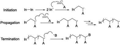
In a typical grafting-from approach, the polymer is synthesized in situ at the surface of the particle.90 The anchoring point is often an initiator or a chain transfer agent (CTA), which is either covalently or physically attached to the particle surface and capable of directing polymer chain growth. Because of the negligible steric hindrance of the anchoring molecule and monomer, the surface functionality coverage and grafting density for the grafting-from approach can reach a theoretical maximum.89 In the case of MOFs, most of these anchoring molecules are difunctionalized, i.e., one functional group can bind to the MOF and another one can trigger the polymerization. Depending on the chemical moieties on the MOF, the anchoring molecules can be designed to make a strong and favorable bond to the MOF.21,22 For example, molecules with a –COOH group can coordinate with metal atoms or react with the –OH group on metal nodes through esterification. Through post-synthetic linker modification, linkers with nucleophilic functional groups such as amines can react with electrophilic anchoring molecules (e.g., acetyl chloride) to form a stable covalent bond. Based on the desired polymer species and polymerization mechanism, the anchoring moiety can be varied. This section will discuss several commonly used polymerization techniques and their applications for grafting polymers from the MOF surface.2.1.1.1. Basics for free radical polymerization. Free radical polymerization (FRP) is the simplest radical polymerization technique that only requires radical generators, reactants (e.g., monomers), and solvents in an oxygen-free solution.91–93 It is usually a three-step process that involves initiation, propagation, and termination (Scheme 1). The radical generator, also termed the initiator, is often AIBN (azobisisobutyronitrile) or potassium persulfate that can be split into two radical species through mild heating (∼60 °C). The generated radicals from the initiator then react with alkene-based monomers to create activated monomers. The propagation step proceeds in a similar fashion to increase the polymer chain length. The active chain end would be terminated by reacting with either another propagating chain end or impurities such as water and oxygen.
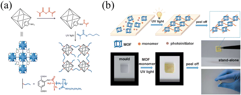
2.1.1.2. FRP on MOFs. Such simplicity in operation makes FRP an ideal solution for facile and economic growth of polymers. To perform a free radical polymerization on a MOF, one must first incorporate a molecule with an alkene group onto the MOF surface. Polymerization can then occur at the alkene group when initiated by the radical generator. As an example, Molavi et al. grew PMMA from the surface of UiO-66-NH2.34 Using a glycidyl methacrylate-modified linker as the surface-anchoring unit to grow PMMA, the resultant PMMA-grafted MOF and MMM exhibited higher helium selectivity thanks to the improved interface of the MOF and polymer matrix. Jiang and co-workers utilized free radical polymerization to graft a pH sensitive poly[(2-diethylamino)ethyl methacrylate] from the surface of UiO-66.39 The pH responsive polymer renders the MOF with dynamic aggregation states in aqueous solution (i.e., dispersed or agglomerated particles) and controllable catalytic performance. Zhang and co-workers demonstrated light-induced free-radical polymerization on MOFs with prototype UiO-66-NH2 (Fig. 1a).35 The linker amino group was post-synthetically modified with a methacrylic anhydride (red molecule in Fig. 1a). The alkene-bearing group anchored on the MOF surface was activated by a photoinitiator and UV light to give surface-grafted poly(butyl methacrylate). The efficient initiation and chain propagation process yielded high molecular weight-grafted polymers, as evidenced by the free-standing film (Fig. 1b). The uniformly dispersed MOF particles across the MMMs resulted in a crack-free morphology and excellent separation capabilities for CrVI ions in water. It is worth noting that such in situ free radical polymerization, which occurs on the particle surface and in the bulk of the mixture, is a bit different from the context of traditional grafting-from. Since polymerization also takes place in the solution, the whole system would turn to a polymeric matrix, unlike a conventional surface modification. The authors referred to such in situ polymerization as postsynthetic polymerization (PSP), as opposed to postsynthetic modification for the MOF field.
Although FRP is relatively easy to operate in comparison to other controlled polymerizations, it inevitably yields low control over the polymer characteristics (e.g., molecular weight and polydispersity) due to the rapid chain growth and side reactions, significantly limiting the application of this technique.
2.1.2.1. Basics of ATRP. Controlled radical polymerization (CRP), which evolved from free radical polymerization, is one of the most widely applied polymerization mechanisms for vinyl-based monomers.94–97 Since it impedes chain propagation, termination, and chain transfer through deactivation of propagating species, it affords polymers with a well-defined chemical structure, controlled molecular weights, and narrow polydispersity. With precise control over the polymerization process, the polymer products are endowed with specific properties and functionalities. There are several major types of CRP techniques including ATRP, RAFT, and nitroxide-mediated polymerization (NMP). All these techniques share one pivotal characteristic: introduction of a dormant species to the propagating radical which significantly slows down the rate of reaction and thus achieves a controlled chain growth.
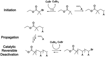
Using ATRP as the first example, the initiator usually contains a halogen group (e.g., bromine) on a tertiary carbon due to the steric effect (Scheme 2). The active halogen can be easily detached from the tertiary carbon by coupling with a transition metal catalyst, typically Cu(I) and Cu(II), forming a radical on the tertiary carbon.98–100 The generated radical can then initiate chain propagation. Unlike FRP, the growing chain end has a favorable coupling tendency with Cu(II) to re-form the C-halogen bond (C–Br in this example) and re-generate Cu(I) species. The large equilibrium constant of this reaction ensures the formation of a dormant butyrate compound instead of a propagating chain end. The reduced propagation reaction rate can therefore reduce the side reactions and maintain a uniform growth of polymer chains.
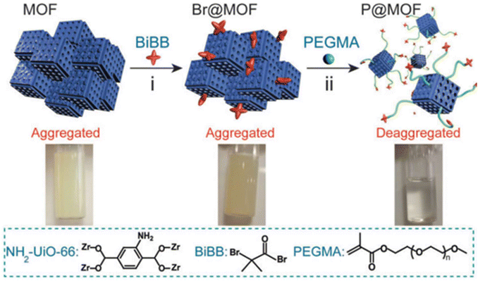
2.1.2.2. ATRP on MOFs. Xie and co-workers exemplified a classic ATRP process on the MOF surface (Fig. 2).48 The first step typically involves attachment of the initiator onto the MOF surface through either a chemical reaction to form a covalent bond or physical adsorption such as a hydrogen bond. The initiator has to remain active after the surface attachment process, i.e., the radical-generating moiety must be intact. In this example, the authors utilized the amino group on the benzoic dicarboxylic acid (BDC) linker of NH2-UiO-66 (a zirconium-based MOF connected by BDC) to attack the butyryl bromide group of the initiator. The reactive species, the bromoisobutyryl group, did not participate in the attachment step and remained functional for the following polymerization initiation. Therefore, polymerization subsequently took place in the presence of a monomer (polyethylene glycol methacrylate) and a catalyst (CuBr) under regular ATRP conditions. Aggregated pristine NH2-UiO-66 became well-dispersed in an aqueous solution upon the grafting of hydrophilic polyethylene glycol (PEG). Owing to the morphological change of the grafted polymer and phase transition properties, the system was provided with stimuli-responsiveness in terms of solution pH (discussed in Section 4.3).
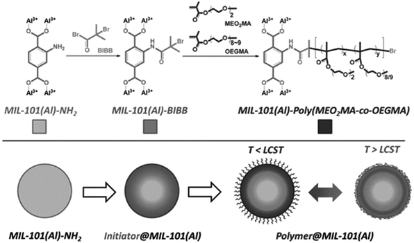
Another example reported by Liu et al. in 2015 further demonstrated the possibility of ATRP on MOFs.54 Using a similar strategy, the amine on BDC linkers attacked the acetyl bromide group on the initiator to decorate the surface of MIL-101 (Al) with the bromoisobutyryl group (Fig. 3). After initiator immobilization, the authors polymerized a thermally switchable copolymer, which had a unique lower critical solution temperature (LCST), off the surface of MIL-101(Al) (Fig. 3). When the temperature rose above the LCST, the grafted polymer phase separated from the solvent, leading to precipitation of the MOF particles. When the temperature dropped below the LCST, the polymer was re-solvated, and the resultant polymer-grafted MOF particles dispersed homogeneously within the aqueous solution. Such a design strategy offers new opportunities to process and recycle MOFs with polymers. More details can be found in Section 4.3.
2.1.2.3. Limitations of ATRP. In summary, ATRP is a powerful technique to graft polymers from MOF surfaces. ATRP not only precisely controls molecular weight, but also is tolerant of a wide range of functional groups. This precision makes it a versatile method for synthesizing a variety of polymers. Currently, most efforts in MOF platforms have been limited to acrylate-based monomers. Expanding the functionalities of surface-grafted polymers on MOFs presents enormous opportunities. However, a transition metal catalyst (e.g., CuBr/CuBr2) can interact with open sites on metal nodes or be captured within the MOF pores, bringing unwanted toxicity and lowering the porosity. The residual metal catalyst not only reduces the pore volume and surface area, but also increases the density of the MOF. Removing the catalyst presents additional complexities to the process as it requires excessive solvent exchange or high temperature, which could be detrimental considering the poor stability of certain MOF species (e.g., MOF-5). Several efforts have been dedicated to designing a photo-initiated electron transfer mechanism to achieve metal-free ATRP.46,101,102 Developing such reactions on MOFs will be an interesting experiment to study. Moreover, ATRP often demands a basic organic ligand (e.g., pentamethyl diethylenetriamine, or PMDETA) to facilitate the dissolution of transition metal catalysts. The basicity of the ligand could lead to potential structural degradation for MOFs.
2.1.3.1. Basics of RAFT. Reversible addition–fragmentation chain transfer (RAFT) polymerization is a versatile and widely used technique under the umbrella of controlled radical polymerization.103–105 Similar to ATRP and other CRP techniques, RAFT polymerization enables the synthesis of well-defined polymer structures and molecular weight control with narrow polydispersity. Compared to ATRP, RAFT offers better kinetic control over the polymerization process that allows more accurate chain length and is more tolerant to impurities (e.g., oxygen). RAFT does not rely on transition metals and therefore is advantageous when producing polymers for biomedical and environmental applications, or other fields that require a low metal content. Moreover, RAFT is well-suited for copolymerization, providing a more complex polymer architecture.
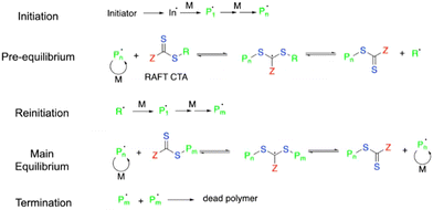
In a typical RAFT process, the initiation takes place at the beginning stage to yield active propagating species (Pn in Scheme 3). A pre-equilibrium step occurs in the presence of a chain transfer agent (CTA). The typical CTA consists of a dithiocarbamate group, with a stabilizing group (Z) to maintain the viability of adduct radicals (middle species in the pre-equilibrium step) and a reinitiating group (R˙) to trigger following polymerization. CTA facilitates the reversible transfer of the growing polymer chain between active species (propagating the chain end with radicals such as Pn˙ and Pm˙) and dormant species (unreacted chain end where the polymer is attached to CTA).106,107 The Z and R groups must be designed in a way to favor the formation of dormant species in the equilibrium step, which can slow down the chain propagation rate and afford a well-controlled polymerization process.
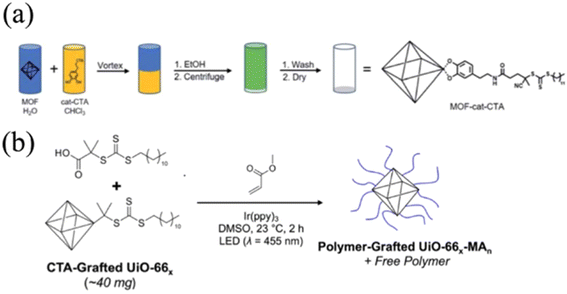
2.1.3.2. RAFT on MOFs. Kyle and Cohen designed a generalized CTA for surface initiated-RAFT (SI-RAFT) polymerization on three types of MOFs, namely, UiO-66(Zr), UiO-66(Zr)-NH2, and MIL-888(Fe)-NH2 (Fig. 4a).58 The catechol bearing-CTA (cat-CTA) was achieved by reacting a –COOH containing RAFT CTA with N-hydroxylsuccinimide, followed by amidization with dopamine. The cat-CTA was able to coordinate with the metal node through the adjacent hydroxyl groups on the catechol moiety. The resultant MOF-cat-CTA subsequently underwent traditional SI-RAFT conditions with methyl methacrylate,87 affording PMMA with controllable molecular weight ranging from 6.3 kg mol−1 to 138 kg mol−1. The facile incorporation of the CTA onto the MOF through the universal metal-hydroxyl interaction makes the approach adaptable to different MOFs. Later, the authors extended the chemistry to surface initiated photoinduced electron transfer RAFT (SI-PET-RAFT) as shown in Fig. 4b.51 In this approach, cat-CTA was first grafted onto the MOF via a similar strategy to that discussed above, and the SI-PET-RAFT process was initiated by LED light (λ = 455 nm) in the presence of a photocatalyst, Ir(ppy)3. The energy harnessed from the photoexcited electron of Ir(ppy)3 facilitated polymerization initiation. The authors demonstrated the generality of SI-PET-RAFT in terms of viable monomers, including PMMA, poly(benzyl methacrylate) (PBnMA), and poly(methyl acrylate) (PMA). Since the polymerization was induced by light, the reaction conditions were simply controlled by switching the light on and off, and the reaction occurred at room temperature. The degree of polymerization (N) was controlled to range from 400 to 4000 by changing the catalyst to monomer ratio. They also observed a decrease of grafting density with higher grafting molecular weight (e.g., grafting density for PMMA dropped from 0.26 to 0.10 chain per nm2 when the molecular weight increased from 52.0 to 319.5 kDa). More importantly, the authors explored the formation of free-standing MOF monolayers through surface polymer entanglement. They found that a high molecular weight (N > 1000) and an intermediate particle size (120 nm) facilitated the monolayer formation. The grafted PMMA gave rise to a brittle MOF monolayer due to the glassy nature of PMMA, whereas grafted rubbery PMA offered a flexible and tough monolayer.
2.1.3.3. Limitations of RAFT. RAFT polymerization essentially expands the spectrum for a wide selection of monomers (e.g., vinyl acetate and acrylamide) because of its excellent compatibility with functional groups. Without the presence of a transition metal catalyst used in ATRP, the RAFT technique showcases a more environmental- and bio-friendly approach. However, the unavoidable CTA might require additional purification processes or protection methods to protect the MOF from degradation. The complexity in the chain transfer equilibrium process demands a careful selection of the Z and R groups for CTA to match the reactivity of various monomers.
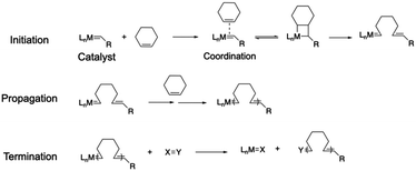
2.1.4.1. Basics of ROMP. Ring-opening metathesis polymerization (ROMP) demonstrates an important polymerization technique for cyclic olefin monomers.108–110 Since its breakthrough in the 1980s, led by Robert H. Grubbs and co-workers, ROMP has gained tremendous attention across the polymer field. It utilizes a transition metal catalyst, typically based on ruthenium or molybdenum, to initiate polymerization by coordinating with the carbon–carbon double bond of the cyclic olefin monomer (Scheme 4). The reactive metal–carbon bond triggers the rearrangement of the other alkene bonds within the monomer, leading to an opening of the cyclic ring and chain propagation (propagation step in Scheme 4). The polymerization is terminated by either consuming all the monomers or reacting with a specific reagent (X = Y in Scheme 4) to deactivate the catalyst.
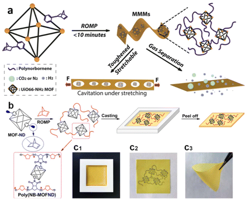
2.1.4.2. ROMP on MOFs. Owing to the high efficiency of coordination between the catalyst and the monomer and the internal ring strain of cyclic monomers, ROMP is able to produce extremely high molecular weight polymers with narrow polydispersity and without byproducts/small molecules, making it a Nobel prize-winning invention. Moreover, ROMP is well-known for its high tolerance for functional groups, allowing the polymer backbone to have desirable architectures and properties. Given such leverages of ROMP, researchers have utilized it to produce a polymer-grafted MOF and free-standing MMMs. Gao et al. fabricated high molecular weight polynorbornene free-standing films through ROMP off a MOF surface (Fig. 5).111 The amine group on the dicarboxylic acid linker of UiO-66-NH2 reacted with the cis-5-norbornene-exo-2,3-dicarboxylic anhydride to afford norbornene-functionalized MOF particles. The norbornene moieties on MOF surfaces subsequently underwent ROMP, yielding free-standing MOF–polynorbornene composite films. The high reactivity of ROMP facilitated an efficient polymerization process that lasted less than 10 minutes. Due to the interfacial bonding from the surface-grafted polynorbornene, the composite MMMs exhibited excellent toughness (the mechanical reinforcement of the MOF–polymer composite is discussed in Section 4.2). The defect-free interphase with a smaller pathway size provided preferred selectivity for H2 over CO2 due to the smaller volume of H2. More importantly, a large-scale synthesis was successfully achieved as a 98 × 165 cm membrane was fabricated through this approach, owing to the mild reaction conditions and high reactivity of ROMP. It demonstrated the technical feasibility of commercialization of the grafting-from approach for MOF–polymer composites.
2.1.4.3. Limitations of ROMP. Although cyclic olefin monomers with desired functionalities have shown great potential in various fields, the monomer choices for ROMP are limited. The metal catalysts used in ROMP also present challenges regarding catalyst removal and recycling. The choice and optimization of the catalysts are crucial to achieve an efficient polymerization for specific monomers, introducing more complexity to the ROMP process.
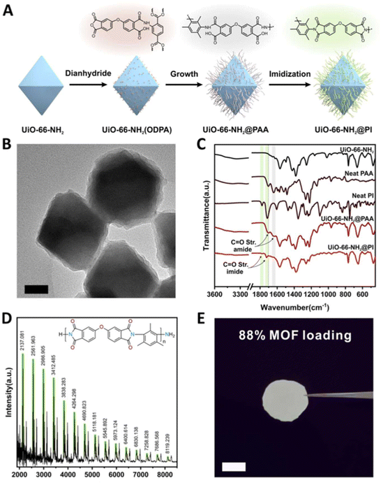
![[double bond, length as m-dash]](https://www.rsc.org/images/entities/char_e001.gif) O imide bond (Fig. 6C), confirming the successful grafting of PI onto the MOF surface. The matrix-assisted laser desorption/ionization-time-of-flight (MALDI-TOF) results revealed a series of peaks ranging from 2–8 kDa with a 425 Da interval, corresponding to the repeating unit of PI (Fig. 6D). Thanks to the strengthened interface of the MOF–polymer membrane, the authors were able to load the free-standing polymer membrane with an exceptionally high weight loading of MOF (88%) in the absence of cracks (Fig. 6E). The engineered MMMs displayed higher ductility and enhanced CO2/N2 and CO2/CH4 separation ability in comparison to unmodified MMMs (discussed in Section 4.2 mechanical reinforcement and Section 4.4 molecular separation, respectively). The authors attributed the observations to the surface brush-matrix polymer entanglements that minimized voids at the interphase and introduced extra mechanical strength.
O imide bond (Fig. 6C), confirming the successful grafting of PI onto the MOF surface. The matrix-assisted laser desorption/ionization-time-of-flight (MALDI-TOF) results revealed a series of peaks ranging from 2–8 kDa with a 425 Da interval, corresponding to the repeating unit of PI (Fig. 6D). Thanks to the strengthened interface of the MOF–polymer membrane, the authors were able to load the free-standing polymer membrane with an exceptionally high weight loading of MOF (88%) in the absence of cracks (Fig. 6E). The engineered MMMs displayed higher ductility and enhanced CO2/N2 and CO2/CH4 separation ability in comparison to unmodified MMMs (discussed in Section 4.2 mechanical reinforcement and Section 4.4 molecular separation, respectively). The authors attributed the observations to the surface brush-matrix polymer entanglements that minimized voids at the interphase and introduced extra mechanical strength.
There are limitations associated with polycondensations. One of the major challenges for step-growth reactions is the slow kinetics: the molecular weight of each growing chain only reaches a significant value at >99% monomer conversion. In addition, the condensation reactions between functional groups proceed slower than the radical reactions. Therefore, polycondensation often suffers from a low degree of polymerization (number of repeating units) and a prolonged reaction time. In fact, it is not uncommon to have a degree of polymerization below 10 for step-growth polymerization and reaction times over 24 hours. It also produces polymers with a high molecular weight dispersity (∼2), which might be detrimental for applications that require precise molecular weight control (e.g., drug delivery and formulation of coatings). Moreover, the small molecule byproduct formed during the condensation process must be removed to push the equilibrium forward and achieve high molecular weights.
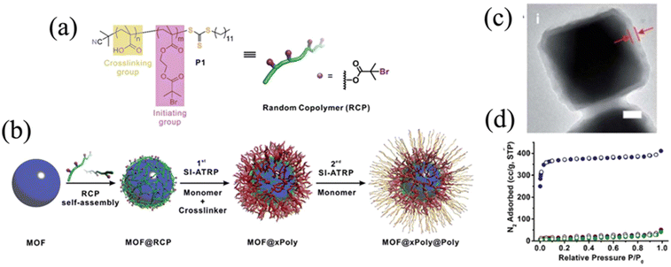
The macroinitiator approach presents a couple of unique advantages over other ATRP methods. The hydrogen bonding ability with the –OH group makes it ubiquitous for various types of MOFs as long as the MOFs contain open sites with a hydroxyl moiety. The bulkiness of the macroinitiator limits its diffusion inside the pores of the MOF and ensures that the polymer is only grown from the surface. In addition to the SI-ATRP, the same research group demonstrated that polymers synthesized via SI-RAFT can also be applied for this PISA methodology, as long as the polymer backbone contains a hydrogen bonding moiety.59,116
2.2. Grafting-to
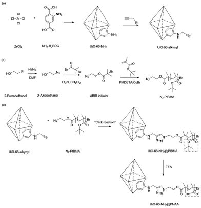
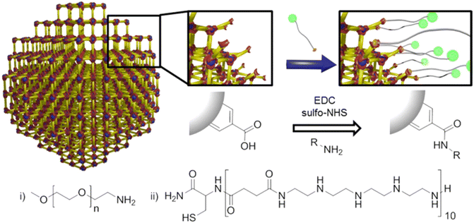
Although the grafting-from approach provides optimal grafting density and a high molecular weight of the surface polymers, it requires additional post-synthetic modification to immobilize an active species, such as the initiator and chain transfer agent, to trigger surface polymerization. Grafting-from also demands a relatively stable MOF scaffold that can withstand the elevated temperature and reactive compounds during the polymerization process. In addition, surface-grown polymers often lack precise control over molecular weight and polydispersity due to the nature of the heterogenous reaction. Therefore, the grafting-to approach has become an alternative strategy to attach polymers to MOF surfaces.117,118 In a typical grafting-to process, pre-synthesized polymers with an active functional end group, such as a hydroxyl or carboxylic group, can react with the MOF surface through metal node coordination or functionalized organic linkers.88 Since the polymers are synthesized in a separate environment without the MOF, the monomer choices, physical structure, and chemical functionality of the polymer backbone can be more readily controlled to meet specific requirements. Li et al. performed a classic grafting-to approach on UiO-66-NH2 through click chemistry, where the MOF and polymers were prepared separately and connected through a simple but efficient chemical reaction (Fig. 8).38 UiO-66-NH2 was first synthesized through a classic solvothermal method and then post-synthetically functionalized with propargyl bromide to give alkynyl-functionalized UiO-66. Concurrently, an azide-containing ATRP initiator was synthesized, followed by an ATRP reaction with tert-butyl methacrylate (tBMA) to yield azide-terminated poly(tert-butyl methacrylate) (N3-PtBMA). Finally, the polymers reacted with the MOF surface through click reactions, and the tert-butyl groups on PtBMA were deprotected, forming polymethacrylic acid (PMAA).Zimpel and co-workers developed a grafting-to strategy to attach amino-polyethylene glycol (PEG5000, Fig. 9i) and Stp 10-C (a bifunctional polyamide, Fig. 9ii) to the surface of the MOF (Fig. 9).36 Through a water-based “green” carbodiimide mediated reaction between amine and –COOH (reaction scheme in Fig. 9), the amine end group of the two polymers covalently attached to the surface of MIL-55(Fe). The PEG functionalized MIL-55(Fe) demonstrated improved colloidal stability and biocompatibility, while the thiol group on the Stp 10-C enabled attachment of fluorescent molecules (green spheres in Fig. 9) for the use of fluorescence microscopy and magnetic resonance imaging. More details about the biomedical application of the modified particles can be found in Section 4.1.
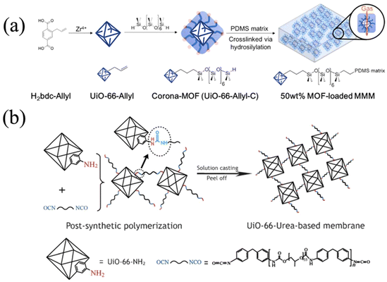
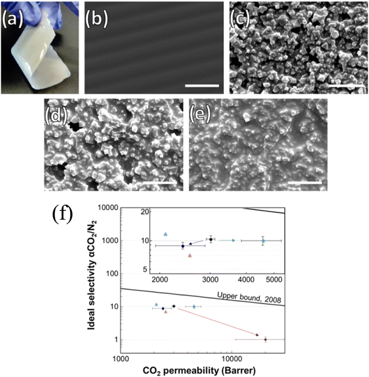
The grafting-to strategy can also be applied to the fabrication of MMMs. Katayama and co-workers grafted poly(dimethyl siloxane) (PDMS) onto allyl-functionalized UiO-66 via hydrosilylation chemistry (Fig. 10a).42 The PDMS-grafted MOF, the so-called corona-MOF with a high density of grafted molecules, was crosslinked with free PDMS chains to afford MOF-loaded MMMs with up to 50 wt% MOF loading. Owing to the strong covalent bonding between the corona-MOF and PDMS matrix and the brush-matrix chain entanglement, the resultant MMMs depicted negligible defects at the MOF–polymer interface (i.e., void-free) and ideal particle dispersion. Since the void gap at the MOF surface was minimized, small molecules would pass through the MOF and large molecules would be rejected, leading to a high permeability and selectivity of gas molecules (more details in Section 4.2). Yao et al. also utilized the grafting-to approach to assist formation of polyurethane-based MMMs (Fig. 10b).43 They specifically chose isocyanate-terminated polyurethane (PU); therefore, both ends of the PU chain can be easily attacked by the amino group on UiO-66-NH2. The covalently bonded MOF and PU matrix resulted in a free-standing and flexible membrane with a high MOF loading percentage (70 wt%). Further structural characterization, including high resolution SEM, proved a well-dispersed and defect-free morphology because of the covalent bonding.
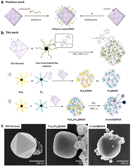
Ahn and co-workers developed a very unique grafting-to approach, producing “patchy” MOF particles with dense polymer grafts attached to the MOF surface, similar to “patches”(Fig. 11).57 Unlike traditional grafting-to or grafting-from (Fig. 11a), their approach utilized a core cross-linked star polymer that contains a thiocarbonylthio moiety (Fig. 11b). The CTA on the star polymer can then react with the vinyl group installed on the BDC ligand of the UiO-66-vinyl surface through the RAFT polymerization mechanism in the presence of a radical initiator AIBN. The radical reaction with the thiocarbonylthio group within the star polymer core offers efficient and functional group-tolerant coupling under mild conditions. This is a general approach, so a great variety of vinyl polymers, synthesized through RAFT polymerization with thiocarbonylthio groups, can be easily attached to the MOF surface, as long as the MOF is functionalized with a vinyl group. The authors demonstrated the decoration of a thick and dense layer composed of two different types of polymers, polylactic acid (PLA) and polystyrene (PS), onto the MOF. Moreover, successful removal of the PLA component was achieved by reacting the PLA/PS-grafted MOF with triethylamine. Upon complete depletion of PLA, the MOF was decorated with a hollow-shell PS layer that can achieve selective dye separation as the MOF porosity was revived. The SEM images showed a thick grafted-polymer layer in comparison to native MOF particles with sharp edges and smooth surfaces (Fig. 11c). Although this work presents a novel strategy to modify the MOF surface with various polymers, obtaining such a core cross-linked star polymer brings extra synthetic complexities and difficulties, significantly limiting the application of this patchwork MOF.
Although the grafting-to approach showcases advantages in terms of optimized polymer characteristics and architectures (e.g., molecular weight distribution) and an overall facile coupling process that does not require an intensive in situ polymerization environment in the presence of MOFs, it has several drawbacks that certainly limit its applications. First of all, the grafting density on the MOF surface is hard to control to achieve an optimal value. The steric hindrance of the pre-synthesized polymer chain makes it difficult for the end group to interact with the functional group on the MOF surface. Secondly, it is not trivial to synthesize polymers with specific end groups that can bond to the MOF surface. In addition, the reaction between the polymer and the MOF surface might occur at a very slow rate, and removing unreacted excess polymers can lead to more difficulties.
2.3. One-pot synthesis of polymer-grafted ZIFs
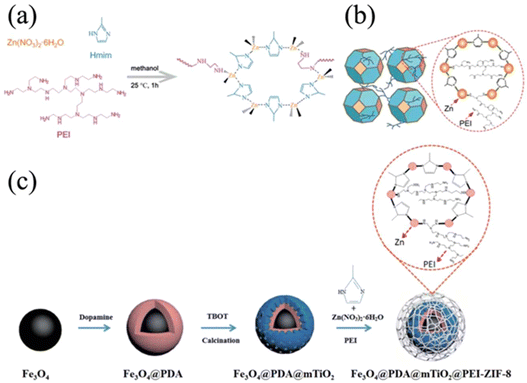
Besides the grafting-to and grafting-from strategies that involve multistep processes such as MOF synthesis, PSM with functional groups, and polymer integration, researchers have developed a unique one-pot synthesis for polymer-grafted MOF particles utilizing the characteristics of both MOFs and polymers. In these examples, zeolitic-imidazolate frameworks (ZIFs), a class of MOFs comprised of tetrahedral metal nodes (M = Zn, Co) and imidazolate-based linkers, were implemented because of the metal-nitrogen linkage. As shown in Fig. 12a, zinc nitrate, 2-methyl imidazole (Hmim), and polyethylenimine11 were added in one-pot, and the mixture solution underwent typical synthesis conditions for ZIF-8.55 Since PEI had similar amine moieties as Hmim, it was successfully incorporated into the scaffold of ZIF-8 (Fig. 12b). The resultant PEI-grafted ZIF-8 was then blended with poly(vinyl amine) (PVAm) to form MMMs. Thanks to hydrogen bonding interactions between the PEI and PVAm, a cavity-free interface between ZIF-8 and the PVAm matrix was achieved, as revealed by SEM images. The closely bound MOF particles and matrix polymers offered an excellent CO2/N2 selectivity in comparison to unmodified ZIF-8/PVAm MMMs. Such selectivity was attributed to the gas pathway through the internal structure of MOFs instead of bypassing through the voids at the MOF surface. Similarly, Yi and co-workers used PEI-grafted ZIF-8 as the outer shell of polydopamine-TiO2 doped Fe3O4 magnetic nanoparticles, which possessed peptide capture and identification properties (Fig. 12c).56 With the introduction of a PEI-grafted ZIF-8 layer, the multifunctional magnetic nanoparticles exhibited better separation and recovery, as well as colloidal stability. However, this one-pot synthetic strategy is limited to MOF systems with nitrogen-based linkers and PEI as grafting polymers due to the structural similarity of the linker and PEI. More generalizable approaches need to be developed to afford broader applicability of this approach.2.4. Remarks on polymers and MOF selections
Although various grafting methods and polymer/MOF species have been discussed in this review, there are some general rules that limit the selection of polymers and MOFs. In the case of the grafting-to approach, the number one consideration for selecting polymers is functional groups. Reactive chemical moieties, such as –OH, –NH2, –SH, and –COOH, are more likely to form strong bonding with MOF surfaces. If the functional groups are present throughout the polymer backbone, the entire molecule would be attached to the MOF, forming a thin layer of polymer chains. If only the end group of the polymer is functionalized, the polymer chains would be dangling from the MOF surface, like a brush morphology. In addition to functionality, polymer chains should be flexible to increase the effectiveness when grafting to the MOF surface. Polymers with stiff backbones, such as polyimide, polyester, and polycarbonate, would be more difficult to be grafted using grafting-to methods.The grafting-from approach is more forgiving when selecting polymers. If a suitable initiator can be mounted onto the MOF surface, any types of polymer chains can be grown from there, theoretically. However, the polymerization condition should not be too harsh to damage MOF particles.
On the other hand, choosing MOFs with the right characteristics is also important for successful polymer grafting. Similar to polymer selection, MOFs with surface functional groups tend to be easier to react with polymers or initiators. The pore size of the MOF should not exceed the size of the polymer; otherwise, the pore of the MOF would be filled with polymer chains. Last but not the least, the stability of the MOF is extremely crucial for this process. The MOF particles must withstand the conditions for all the post-synthetic modifications. One should scrutinize the thermal and chemical stability of the MOF of interest under the experimental conditions. The MOF must maintain the crystallinity, porosity, and chemical structures after the treatment.
3. Characterization of surface-grafted polymers
To better understand the properties of surface-grafted polymer chains and performance-grafted MOFs, it is important to evaluate the characteristics of the polymers, including the molecular weight, grafting density, chemical identity, and bonding type to the MOFs. Herein, we discuss universal guidance on how to characterize and obtain various information from the surface-grafted polymers on MOFs.3.1. General sample preparation guidelines
The two basic approaches are (1) non-destructive and (2) destructive methods. For the former approach, the polymer-grafted MOFs are analyzed while the MOF and polymer structures remain intact, and no further treatment is applied to the grafted particle. In this fashion, one can not only recover the compound after analysis but also investigate the original properties and structures without interference. Characterization methods such as infrared spectroscopy, Raman spectroscopy, scanning electron microscopy (SEM), transition electron microscopy (TEM), and energy dispersive X-ray spectroscopy (EDS) can be performed to identify the physical and chemical structures of the grafted polymer. Note that these non-destructive methods produce features of both polymers and MOF particles since they are attached. One would need to separate the polymer characteristics from the MOFs. If both the polymer and MOF contain similar chemical or physical properties, the non-destructive approach would not be apparent. For example, if one uses IR to detect the C![[double bond, length as m-dash]](https://www.rsc.org/images/entities/char_e001.gif) O group in the grafted PMMA, the carboxylate group in the organic linker of the MOFs would appear in the spectrum and disturb the conclusion.
O group in the grafted PMMA, the carboxylate group in the organic linker of the MOFs would appear in the spectrum and disturb the conclusion.
In this case, a destructive approach would be proposed. Using this method, either the polymer or MOF is degraded for separation and further analysis. The following section regarding molecular weight utilizes this ideology to extract information about the grafted polymers. Once the MOF is degraded and the polymer remains intact, given the right digestion condition, the polymer can then be purified and isolated for conventional polymer characterization, such as size exclusion chromatography (SEC) and nuclear magnetic resonance (NMR) spectroscopy. The destructive approach provides an efficient way to remove the MOF particles and analyze grafted polymers alone.
3.2. Molecular weight
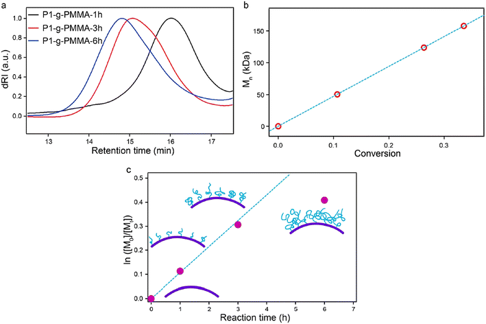
As one of the most important parameters for polymers, molecular weight largely determines the physical properties.17,81 Generally, longer polymer chains (those with higher molecular weight) result in more frequent chain entanglement and thus, greater mechanical strength. As a trade-off of improved mechanical properties, the viscosity increases with higher molecular weight, resulting in a decrease in processability. For polymer-grafted particles, higher grafting chain length often suggests stronger interactions with the surrounding environment, affording desired performance.Obtaining the molecular weight of the grafted polymer requires separation of the polymer from the MOF surface. For covalently attached polymers, the most common practice is to decompose MOF particles by adding reactive molecules, such as acid and base.67 Yang et al. used sulfuric acid to digest the MOF while keeping grafted PMMA intact.67 The polymer was grafted onto the surface of PCN-222 (denoted P1 in the paper) by SI-ATRP. After dissociation from the MOF surface, the solution containing the isolated polymer chains and MOF debris was filtered so that polymer chains could be preserved and analyzed by SEC. As shown in the SEC traces (Fig. 13a), the retention time of the elutes decreases as the polymerization time increases from 1 to 6 h, suggesting an increase in the molecular weight. Based on the linear relationship of monomer conversion (Fig. 13b), the living characteristics of the SI-ATRP for this system was revealed. The reaction kinetics (Fig. 13c), on the other hand, showed that the growth of PMMA was impeded as the molecular weight increased and chain entanglement occurred.
3.3. Grafting density
In addition to molecular weight, high grafting density also ensures the ideal performance of polymer-grafted MOF particles in a medium. Theoretically, higher grafting density would provide a denser polymeric interface that optimizes the surface polymer–matrix interactions through chain entanglement.17,81 Measuring the grafting density (σ) would utilize the equation shown below: | (1) |
3.4. Bonding type identification
The type of bonding between MOFs and polymers is another important factor to be considered. Whether the polymers are anchored to the MOF surface through a covalent bond, an ionic bond, or through physical adsorption such as a hydrogen bond, the stability and other properties of the polymer-grafted MOFs can be significantly impacted. FT-IR spectroscopy, which measures the vibrational frequencies of different chemical bonds, can be used to identify covalent interaction, because it can decipher specific bonding structures, such as ester and amide bonds, formed between the MOFs and polymers. 1H-NMR spectroscopy is another option, as the protons near the newly formed bond can have different chemical shifts in comparison to its original state. Both FT-IR and 1H-NMR spectroscopy can be used to identify hydrogen bond formation as well, since the bond vibration and proton environment would be changed after forming the hydrogen bond. X-ray photoelectron spectroscopy (XPS) provides insights into the electronic state of the atoms at the MOF surface. Therefore, if the bonding formation is associated with changes in the electronic state, e.g., the redox reaction, XPS could potentially detect such events. In addition to covalent bonding, another interaction to form polymer MOF hybrid materials is via physisorption. Common physisorption examples include hydrogen bonding, π–π stacking, and electrostatic interactions. Those interacting forces can improve the interface compatibility between the two phases. Fotovat et al. introduced the UIO-66-NH2/Urea-POP, where the urea (–NHCONH–) from Urea-POP could form the hydrogen bond with amine(–NH2) on the MOF linker and Zr-oxo cluster.119 FT-IR showed a slight peak shift of N–H stretching from 3448 to 3440 cm−1, which was attributed to the formation of the hydrogen bond.Although it is important to identify the bonding type between MOFs and grafted polymers, most of the literature does not document this feature, assuming that the bonding type is as expected. The field would greatly benefit from an in-depth investigation into the bonding nature of each grafting approach to provide a better understanding of the interface. The characterization techniques mentioned above serve as reasonable starting points.
4. Applications
Grafting polymers onto MOF surfaces expands the scope of the properties and applications of MOFs, not only for MOF powders and suspensions but also as MOF–polymer MMMs. With a polymer-engineered surface, MOFs are endowed with desirable surface properties, such as hydrophobicity/hydrophilicity, various zeta potentials, stimuli-responsive dispersion, biocompatibility, and tunable surface pore sizes. All of these surface properties facilitate unique interactions with the surrounding environment and afford unprecedented applications to MOFs.22,23,73 Moreover, polymers at the MOF surface are able to provide favorable interactions with the polymer matrix in MMMs, giving rise to a void-free interface and defect-free composites. Such an enhanced interfacial morphology creates exceptional properties in comparison to non-functionalized MOF MMMs. Thanks to the polymer-grafted MOF particles, the weight loading of MOFs within a MMM can be maximized (e.g., 88 wt%),45 further amplifying the functions brought by MOFs. In this section, we highlight several widely used applications derived from the unique properties of polymer-grafted MOFs.4.1. Biomedical applications
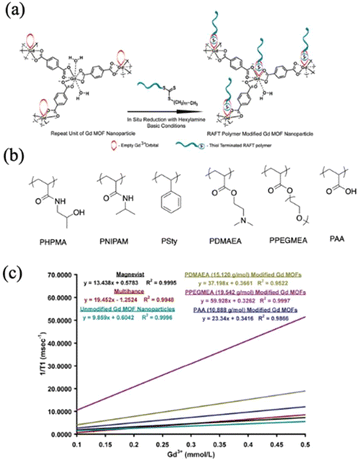
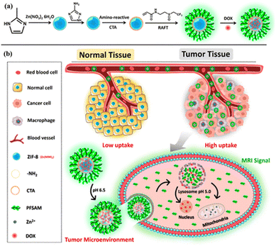
One major bioimaging technique is magnetic resonance imaging (MRI). MRI detects the characteristics of the hydrogen nuclei of water molecules at the target area. Therefore, contrast agents that can increase the relaxation rate of water are applied to enhance the contrast between specific organs or tissues and the surrounding environment.122,123 The most commonly used contrast agent is Gd-chelate compounds because of the shortened longitudinal relaxation time (T1) and high longitudinal relaxivity (r1, defined as the inverse of the relaxation time with respect to the contrast agent concentration).124,125 A combined decreased T1 and enlarged r1 indicates high contrast MRI results. In a study reported by Rowe and co-workers where they synthesized polymer-grafted Gd MOF nanoparticles via the grafting-to strategy (Fig. 15a), the authors studied the relaxation behavior with respect to the characteristics of grafted polymers.40 Both hydrophobic and hydrophilic polymers with different molecular weights were attached to the Gd MOF nanoparticles (Fig. 15b). The relaxation data T1 were obtained as a function of Gd3+ concentration, and one example of the data is plotted in Fig. 15c, corresponding to the last series in Table 2. The slope of the linear fitting of the data yielded the relaxivity, r1. The results are summarized in Table 2. PHPMA, PNIPAM, PDMAEA, PPEGMEA, and PAA grafted Gd MOF nanoparticles increased the relaxivity in comparison to clinically employed Manevist and Multihance, as well as unmodified Gd MOF nanoparticles. The authors attributed this observation to the increased water retention resulting from the grafted hydrophilic polymers. Higher water retention facilitated more favored interactions between the water molecules and Gd3+ within the MOF framework. This phenomenon was also supported by the molecular weight effect, where relaxivity increased with longer polymer chains and prolonged water retention. In contrast, grafting a hydrophobic polymer PSty on Gd MOFs drastically extended the relaxation time and lowered relaxivity. Moreover, hydrophilic polymer grafted Gd MOF nanoparticles exhibited a lower r2/r1 ratio in comparison to the control sample, which further suggested higher positive MRI contrast signals. In a follow-up work, Rowe and co-workers attached not only hydrophilic polymers, but also fluorescent tag molecules onto a Gd MOF to achieve bimodal imaging ability of MRI and optics.37 More recently, Wang and co-workers grafted a multifunctional polymer, poly(N-(2-((2,2,2-trifluoroethyl)sulfinyl)ethyl)acrylamide) (PFSAM), onto the surface of ZIF-8 using the grafting-from method (Fig. 16).61 PFSAM, synthesized using the RAFT mechanism in situ, exhibited excellent hydrophilicity and low-fouling properties, making it a great candidate for bioconjunction and cell uptake. The incorporation of PFSAM increased the aqueous stability of ZIF-8 and imparted efficient delivery to the tumor cells. More importantly, tumor cell was detected by the fluorinated polymer via the 19F MRI signal. The authors further loaded ZIF-8 with a chemotherapeutic drug doxorubicin hydrochloride (DOX) and zinc ions to effectively kill tumor cells.
| Contrast agent | r 1 (s−1 mM−1) | r 2 (s−1 mM−1) | r 2/r1 |
|---|---|---|---|
| PHPMA = poly[N-(2-hydroxylpropyl)methacrylamide], PNIPAM = poly(N-isopropylacrylamide), PSty = polystyrene, PDMAEA = poly(2-(dimethylamino)ethyl acrylate), PPEGMEA = poly(((poly)ethylene glycol methyl ether) acrylate), and PAA = poly(acrylic acid). | |||
| Magnevist | 13.44 | 21.40 | 1.59 |
| Multihance | 19.45 | 30.44 | 1.57 |
| Unmodified Gd MOF nanoparticles | 9.86 | 17.94 | 1.82 |
| PHPMA (5327 g mol−1) modified Gd MOF nanoparticles | 17.81 | 25.77 | 1.45 |
PHPMA (10![[thin space (1/6-em)]](https://www.rsc.org/images/entities/char_2009.gif) 281 g mol−1) modified Gd MOF nanoparticles 281 g mol−1) modified Gd MOF nanoparticles |
32.94 | 44.85 | 1.36 |
PHPMA (19![[thin space (1/6-em)]](https://www.rsc.org/images/entities/char_2009.gif) 370 g mol−1) modified Gd MOF nanoparticles 370 g mol−1) modified Gd MOF nanoparticles |
105.36 | 129.63 | 1.23 |
| PNIPAM (5690 g mol−1) modified Gd MOF nanoparticles | 20.27 | 29.73 | 1.47 |
| PNIPAM (8606 g mol−1) modified Gd MOF nanoparticles | 46.99 | 64.10 | 1.36 |
PNIPAM (17![[thin space (1/6-em)]](https://www.rsc.org/images/entities/char_2009.gif) 846 g mol−1) modified Gd MOF nanoparticles 846 g mol−1) modified Gd MOF nanoparticles |
62.51 | 79.90 | 1.28 |
| PSty (4802 g mol−1) modified Gd MOF nanoparticles | 1.17 | 14.16 | 12.10 |
| PSty (8972 g mol−1) modified Gd MOF nanoparticles | 1.20 | 25.75 | 21.46 |
PSty (15![[thin space (1/6-em)]](https://www.rsc.org/images/entities/char_2009.gif) 245 g mol−1) modified Gd MOF nanoparticles 245 g mol−1) modified Gd MOF nanoparticles |
3.91 | 123.40 | 31.56 |
PDMAEA (15![[thin space (1/6-em)]](https://www.rsc.org/images/entities/char_2009.gif) 120 g mol−1) modified Gd MOF nanoparticles 120 g mol−1) modified Gd MOF nanoparticles |
37.20 | 54.17 | 1.46 |
PPEGMEA (19![[thin space (1/6-em)]](https://www.rsc.org/images/entities/char_2009.gif) 542 g mol−1) modified Gd MOF nanoparticles 542 g mol−1) modified Gd MOF nanoparticles |
59.93 | 81.55 | 1.36 |
PAA (10![[thin space (1/6-em)]](https://www.rsc.org/images/entities/char_2009.gif) 888 g mol−1) modified Gd MOF nanoparticles 888 g mol−1) modified Gd MOF nanoparticles |
21.30 | 31.82 | 1.49 |
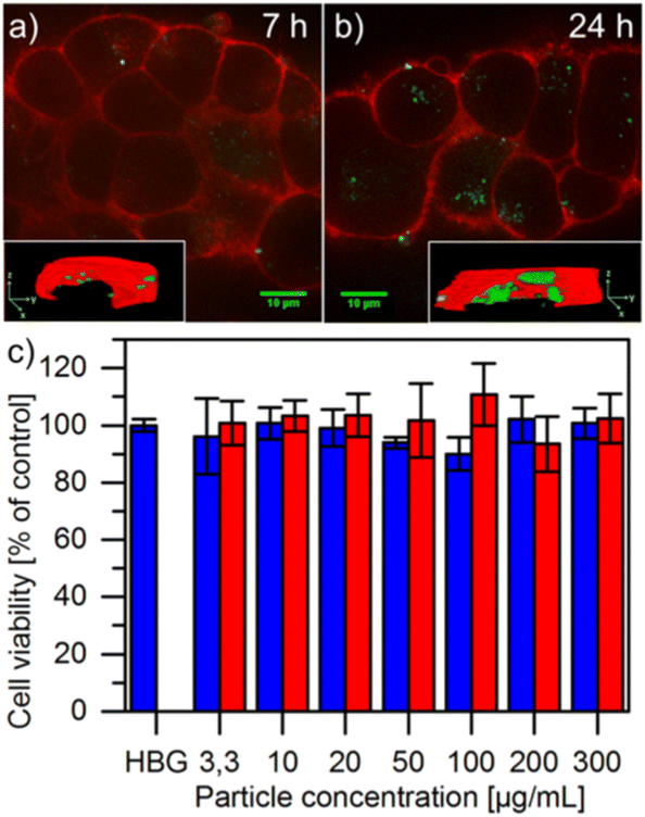
Zimpel et al. also attached fluorescent-labeled grafted polymers onto MIL-100(Fe) via grafting-to for in vivo fluorescence imaging (Fig. 9 and Fig. 17).36 The fluorophore, Cyanine5 maleimide, was easily attached to the polymer Stp10-C through the thiol group (the structure of Stp10-C can be found in Fig. 9). The functionalized MOF nanoparticles aggregated at targeted N2A cell surfaces after 24 h incubation, evidenced by strong fluorescent signals (Fig. 17b). The polymer grafted MOF particles (red) also exhibited higher cell viability after 24 h in comparison to unmodified MOF MIL-100(Fe) (blue) (Fig. 17c). In another work, Tant and co-workers tested poly(phenylene sulfide)-grafted terbium (Tb)-based MOFs (through grafting-from) in terms of their luminescent properties under visible light, showing the potential of using the MOFs as optical sensors.49
4.2. Mechanical reinforcement
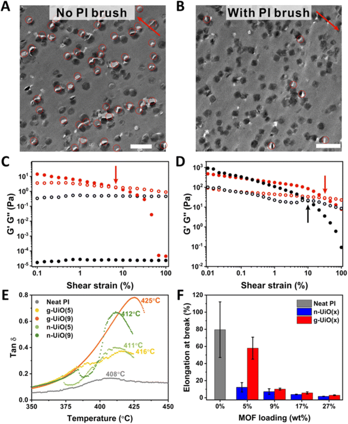
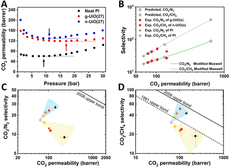
Mechanically reinforced polymer composites have been thoroughly investigated since they are ideal, light-weight materials for the aerospace and automotive industries.126–129 With the addition of reinforcing fillers, the polymer matrix can exhibit comparable mechanical strength as inorganic materials (e.g., aluminum and steel) at a much lower weight due to the low density of polymers. Some common fillers are TiO2 nanoparticles, carbon black nanoparticles, carbon nanofibers, and graphene. However, one severe drawback for such particle-reinforced polymer composites is the weak interfacial adhesion between the particle filler and the polymer matrix. Such poor interactions at the interface could cause particle aggregation, defects upon deformation, and concentrated local stress, all of which are detrimental to mechanical performance. Grafting polymers onto the particle surface is an ideal solution because the surface polymer can provide a sufficient interaction with the matrix polymer, resulting in a strengthened interface and composite.MOF–polymer composites present several advantages for mechanical reinforcement including low weight loading (i.e., low density of MOF), high specific modulus, and good processability. Researchers have, therefore, utilized polymer grafting to increase the mechanical properties of the MOF–polymer composites. Wang and co-workers synthesized polyimide (PI)-grafted UiO-66-NH2 through the grafting-to strategy, and they manufactured void-free MMMs using PI as the matrix (synthesis in Fig. 6 and results in Fig. 19).45 TEM images of the microtomed MMM thin slices without (Fig. 19A) and with (Fig. 19B) grafted PI showed less dislocation of MOF particles after PI grafting, manifesting the improved interface. The PI-grafted MOF composite demonstrated improved interfacial adhesion through polymer chain penetration as evidenced by the mechanical measurements. The authors prepared a grafted-MOF/2-pyrrolidone (NMP) suspension to discover the rheological properties of the polymer-grafted MOF. As expected, a pristine MOF/NMP mixture (Fig. 19C, black) displayed typical liquid-like rheology, as the loss modulus (G′′) was higher than the storage modulus (G′). However, the PI-grafted MOF/NMP mixture (Fig. 19C, red) was found to show a solid-like behavior at a low shear strain (<7%) as G′ > G′′. The mixture returned to liquid-like behavior at a higher strain, as the strain was large enough to disassemble the particle aggregates. The authors attributed this observation to the strong interpenetration of polymers at MOF particle surfaces which inter-locked the MOF particles during low shear strain. The chain solidification was revealed by Tg from Tan![[thin space (1/6-em)]](https://www.rsc.org/images/entities/char_2009.gif) δ (
δ ( ) vs. temperature relationship (Fig. 19E). The PI-grafted MOF (g-UiO) composite exhibited the highest Tg among the neat polymer and pristine MOF composite (n-UiO). With a higher weight loading of the MOF particle (9% vs. 5%), Tg was further increased to 425 °C. Since Tg is directly related to polymer chain mobility, the PI-grafted MOF again demonstrated an enhanced polymer–polymer interpenetration, which limited chain movement at the particle surface. Furthermore, the grafted MOF displayed much higher elongation-at-break at 5 wt% loading in comparison to all other MOF-reinforced MMMs (Fig. 19F).
Liu and co-workers systematically varied the grafting density and chain length to investigate the fracture behavior of MOF–polymer nanocomposites (Fig. 20).52 By performing a grafting-to approach, they were able to synthesize poly(alkyl glycidyl ether)-grafted nanosized ZIF-8 (diameter = 50 nm), which was then fabricated along with the PMMA matrix to produce MMMs. Using high resolution TEM, the authors probed the fracturing mechanism for various grafting conditions. As depicted by Fig. 18 (left figure), a short polymer brush length (5.7 kDa) with a high grafting density (0.35 chains per nm2) gave rise to long cracks in the MMM upon fracturing, indicating non-sufficient particle-matrix interaction and stress dissipation. Such long cracks could easily propagate through the material and cause fractures. As the brush length increased to >34 kDa (middle figure of Fig. 20), the low grafting density samples (0.14 chains per nm2) showed cavitation and shear banding (a confined zone of excessive shearing strain and plastic deformation) instead of large crazing behavior. It suggested an improved fracturing mechanism, as the cavitation and shear banding were able to constrain the internal strain. The best toughening effect was observed for high brush length and high grafting density (right figure of Fig. 20). A homogeneous crazing phenomenon was observed at the surface of each of the grafted MOF particles, which allowed a uniform dissipation of stress and strain. The massive crazing distributed across individual particles provided a noteworthy toughening effect. The results presented a systematic control over the control of toughness of MOF–polymer nanocomposites. A similar toughening effect was achieved by Gao et al. where they utilized the ROMP technique to synthesize surface-grafted MMMs with strong interfacial bonding (synthesis procedure discussed in Section 2.1.4.2).111
Surface-grafted polymer chains on MOFs bring extra reinforcement to the system in comparison to pristine MOFs. As illustrated in this section, grafted polymers can entangle with matrix polymers (or in some cases, provide bonding interactions, such as a hydrogen bond) and thus, improve overall reinforced mechanical performance. The wide selection of polymer chemistry approaches and MOF substrates generates opportunities to strategically modify MOF surfaces. By controlling the polymer characteristics, such as molecular weight and grafting density, different matrix polymer species and properties can be accommodated. Polymer chemistry at MOF surfaces has provided researchers powerful tools to engineer the mechanical properties of the system.
4.3. Stimuli-responsive reactions
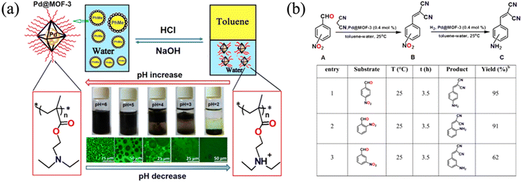
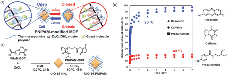
One important characteristic of polymers is their dynamic responsiveness to various stimuli such as pH and temperature. Utilizing this dynamic change of polymer chain conformation and properties, one can easily adjust the colloidal stability and particle surface morphology to obtain different functions. Jiang et al. grafted pH-sensitive poly(diethylamino ethyl methacrylate) (PDEAEMA) onto the surface of palladium-loaded MOF-3 (Pd@MOF-3) (Fig. 21a) for dynamic catalysis.39 The polymer-grafted MOFs facilitate the formation of Pickering emulsion to perform Knoevenagel condensation-hydrogenation cascade reactions, since the reactant was soluble in the oil emulsion. The surface PDEAEMA was deprotonated in basic solution, making the MOF particles hydrophobic. Therefore, the MOF particles could serve as an emulsion stabilizer of toluene droplets in water (Fig. 21a). As pH decreased, protonated PDEAEMA made the MOF hydrophilic, and therefore, the MOF particles remained in the water phase after toluene–water phase separation. Such a phenomenon was proved by optical and confocal microscopy images. The MOF-stabilized Pickering emulsion was then tested for the cascade reactions of nitrobenzaldehydes (Fig. 21b). A 95% yield was observed for para-substituted nitrobenzaldehydes at room temperature for 3.5 h. This unique system showcased a great example of pH-controlled emulsion formation for efficient catalytic reaction at the water–oil interphase where MOF particles resided. A very similar strategy was demonstrated by Xie et al. where they used poly(ethylene glycol methacrylate) as a pH sensitive surface polymer to control the aggregation of Pd-loaded MOFs and thus, catalytic reactions.48 At pH 9, the suspended MOF particles were able to catalyze reduction of 4-nitrophenol with a 2 h turn over number of ∼5. However, under acidic conditions, the carboxyl group on the PEG became protonated and more hydrophobic, resulting in particle aggregation and loss of catalytic performance.While pH-responsive polymers present a facile strategy to manipulate reaction dynamics, the switching behavior requires the introduction of additional acids/bases to a solution and thus, is dependent on the stability range of the MOFs. Another efficient method to control polymer conformation at a MOF surface is through temperature, since certain polymer species exhibit unique thermal responses. The most widely used thermally responsive polymer is poly(N-isopropylacrylamide) (PNIPAM), which undergoes phase transition at a low critical solution temperature (LCST, below which phase transition starts).103 When the temperature increases above Tc (32 °C), PNIPAM in water changes from a coil conformational state (dissolution) to a globule (aggregation) state, becoming insoluble in water. Such a low temperature phase transition is extremely easy to achieve and not detrimental to most MOFs and biological systems. This transition makes PNIPAM a promising candidate for thermally responsive functional moiety to MOFs. Nagata et al. grafted PNIPAM onto UiO-66-NH2 to develop an on–off thermal switch on MOF surfaces (Fig. 22).41 At room temperature (below 32 °C), the surface-grafted PNIPAM maintained a coil conformation and helped stabilize the MOF suspension in water. More importantly, the MOF surface was exposed to the surrounding environment, creating an open pore morphology at the MOF surface. When the temperature increased above 32 °C, the polymer became a globule state and closed the surface pores of the MOF. Such a dynamic variation of the MOF surface made PNIPAM-grafted UiO-66-NH2 an ideal carrier for controlled drug delivery (Fig. 22c). To demonstrate the application of this on–off switch system, they loaded the MOF with different guest molecules and showed that the molecules were able to be efficiently released at 25 °C but not at 40 °C since the surface pores were closed. In addition to PNIPAM, Liu and co-workers utilized a thermally switchable copolymer, poly[(methoxy ethoxy)ethyl methacrylate]-co-oligo(ethylene glycol), to functionalize MIL-101(Al)-NH2 (Fig. 3 and Section 2.1.2.2).54 Since the copolymer exhibited LCST behavior, the MOF particle dispersity in water was easily controlled by varying the temperature. The control of polymer chain conformation offers a facile route to manage the catalytic reaction.
Even though a conventional MOF system often does not have stimuli-responsiveness, grafting specialized polymers onto the MOF surface can bring such properties. As shown in the examples above, a variety of reactive polymer chains have been attached to the MOF surface to make it responsive to heat and/or the pH of a solvent. The grafted MOFs exhibit selective catalysis, controllable colloidal stability, and targeted molecule delivery. In the future, we anticipate that more ‘smart’ MOFs will be designed and synthesized to bring unprecedent opportunities.
4.4. Molecular separation
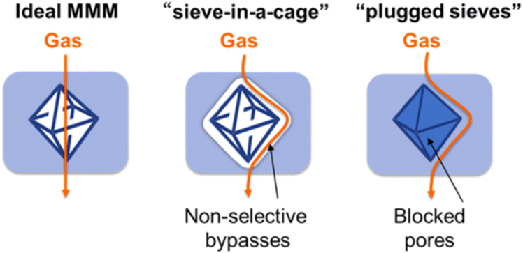
Owing to the high porosity and tunable pore sizes, one of the most important applications of MOFs is their selective separation of small molecules such as CO2, N2, and dye molecules by means of size selectivity. In order to expand the usability of MOFs for separation applications, it is important to fabricate MOF–polymer composites, such as MMMs or MOF-decorated polymer fibers, where the polymers can serve as a matrix platform to transport and stabilize MOF powders.34,45,50,55 However, attempts to combine MOFs and polymers into MMMs inevitably reduce the accessible pore area due to the surrounding polymers. As illustrated in Fig. 23 by Cohen and co-workers, the interface between the MOF and the polymer in a MMM plays an important role in determining the gas pathway within the composite.42 When the MOF has a favorable interaction with the matrix polymer through an engineered MOF surface (e.g., polymer grafting), the interface is optimized and the gas molecules are forced to transport through the MOF, maximizing the advantages of the MOF's high internal surface area. In another scenario, the unmodified MOF surface repels the matrix polymer chain due to the steric hindrance and unfavorable interaction, creating voids around the MOF surface. Such a “sieve-in-a-cage” architecture leads to non-selective bypasses of the gas, and the porosity of the MOF is not being utilized. The worst mechanism is the “plugged sieves” configuration, where the surface of the MOF is completely blocked by the matrix polymer through polymer penetration inside the pores. Therefore, all the pathways of the gas molecules are impeded, and the MMMs essentially act as a solid polymer membrane with poor transportation of any compounds.In the work reported by Katayama and co-workers, an ideal MMM architecture was achieved by grafting PDMS onto MOF surfaces and further cross-linking with a matrix polymer (Fig. 10a and 24).42 The strengthened interface helped form defect-free MMM, as seen in SEM images (Fig. 24e). UiO-66-allyl MMM, UiO-66-allyl-PDMS MMM, and UiO-66-allyl-C MMM (C stands for cross-linked) showed a drastically different surface morphology. With pristine UiO-66-allyl MMM, severe particle aggregation and heterogeneity were observed (Fig. 24c), whereas PDMS-grafted UiO-66-allyl MMM exhibited less aggregation, but still showed some notable defects at the MMM surface (Fig. 24d). After cross-linking the surface PDMS with matrix PDMS, a homogeneous and defect-free MMM was obtained (Fig. 24e). The subsequent gas permeation measurements revealed the effect of different architectures on CO2 permeability and CO2/N2 selectivity (Fig. 24f). Pristine PDMS (black circle) depicted a reasonable CO2/N2 selectivity and low CO2 permeability because of the intrinsic free volume of the polymer. After introducing unfunctionalized MOF UiO-66-allyl (red circle), the permeability increased dramatically (∼5 fold) but the selectivity dropped by a factor of ∼10. It demonstrated that pristine MOF MMMs gave rise to a “sieve-in-a-cage” architecture, with high defect levels and voids, which promoted non-selective bypasses. PDMS-grafted UiO-66-allyl MMM (blue circle), on the other hand, showed lower permeability and selectivity in comparison to pristine PDMS membranes, since the surface of the MOF was blocked by polymers (plugged sieves). The best performance was observed for surface cross-linked MMMs (green circle) which resembled ideal MMMs. The strengthened defect-free interface helped restore the selectivity of the MOF and increased CO2 permeability. Cseri and co-workers also investigated the interfacial gap of UiO-series MMMs for precise molecular sieving (Fig. 25).53 Three types of amine-functionalized UiO MOFs (UiO-66-NH2, UiO-67-NH2, and UiO-68-NH2) were studied, all of which were grafted with PNIPAM for enhanced interfacial adhesion with the matrix polymer. In comparison to pristine UiO-66-NH2 MMM (Fig. 25a), UiO-66-PNIPAM MMM (M66P) showed homogeneous particle distribution and negligible defects at both the surface and the cross-section (Fig. 25b and c). The authors performed systematic experiments to investigate the rejection rate on these MMMs with regard to organic compounds with various molecular weights (Fig. 25d). Among the three PNIPAM-grafted UiO MOFs (M66P, M68P, and M68P), M66P displayed the sharpest transition from small MW to large MW compounds. It indicated an accurate cut-off MW for separating different compounds and thus the best sieving performance. The fact that UiO-66 has the smallest pore size of the three MOFs gave it advantages in separating compounds with various sizes. Moreover, all the PNIPAM-grafted MOF MMMs presented improved rejection efficiency in comparison to unfunctionalized MOF MMMs, highlighting the importance of the defect-free MMM morphology.
Another excellent example was demonstrated by Wang and co-workers (Fig. 26).45 PI-grafted UiO-66 (g-UiO, Fig. 26) not only exhibited reinforced mechanical properties (Fig. 19) but also showed superior gas separation performance. Both of the PI-grafted MOF (g-UiO(27), where 27 denoted the MOF particle wt%) and pristine MOF MMMs (n-UiO(27)) showed a higher CO2 permeability under the same pressure, in comparison to the neat PI membrane (Fig. 26A). The MOF within the PI membrane increased gas permeability by providing gas pathways through the internal pores of the MOF. More importantly, the plasticization pressure, which is defined as the point where the permeability increases with pressure, was increased from 9 to 11 to 17 bar for neat PI, n-UiO(27), and g-UiO(27), respectively. Since plasticization is an unwanted softening effect, and higher plasticization is an indication of higher chain entanglement, g-UiO(27) MMMs showed the most promising performance resisting pressure effects. The surface anchored PI was hypothesized to provide extra entanglement with the matrix PI and thus limit the chain mobility. Fig. 26C and D illustrate the gas separation performance for these samples (x denotes different MOF wt% and from yellow to black the wt.% increased) Compared to neat PI (white box), g-UiO(x) showed a simultaneous enhancement in CO2 permeability and CO2/N2 or CO2/CH4 selectivity. The results suggested that the interface remained defect-free and an ideal MMM architecture (Fig. 23) was maintained even though the MOF loading increased to 27wt%. For n-UiO(x), on the other hand, the CO2 permeability increased but the selectivity dropped significantly with higher MOF loading. The loss of selectivity was an indication of a poor MOF–polymer interface and the possibility of a “sieve-in-a-cage” architecture. Therefore, this work again demonstrated the effect of an engineered interface on the polymer chain mobility and the gas separation performance. In addition to gas molecules, separation of dye molecules can also be achieved using similar design criteria. Yao et al. synthesized PU-grafted UiO-66-NH2 based free-standing MMMs for dye removal and selective separation, and their work also demonstrated the significance of using polymer-grafted MOFs instead of unmodified particles.43
In summary, overcoming the defects and poor interfacial properties of MOF-based MMMs is the key to simultaneous enhancement of molecular selectivity and permeability. In traditional materials, the trade-off between high selectivity and permeability often limits the overall performance. When more accessible “gaps” are opened up, such as increased polymer-free volume and membrane defects, the permeability increases but the selectivity inevitably decreases because of the extra molecule pathways. Introducing MOFs to a polymer matrix can provide significant pathways for molecules and potential selectivity, thanks to the high internal surface area and tunable porous structure of MOFs. However, un-modified MOFs often create undesired voids or polymer infiltration near the MOF surface, which drastically reduces the selectivity. The ability to prepare defect-free homogeneous polymer-grafted MOF MMMs led to demonstrations of superior gas-separation performance. Moving away from non-ideal architectures such as “sieve-in-a-cage” and “plugged sieves”, ideal MMMs with near-perfect MOF–polymer interfaces not only maintained the gas selectivity based on the MOF pore sizes, but also brought high permeability at low pressure. Hence, engineering the MOF surface with favorable MOF–polymer interactions is a promising route for large-scale practical MMMs in the molecular separation industry.
5. Outlook
In this review, we first outlined different synthetic approaches to grow polymers from MOF surfaces using a grafting-from approach. Grafted polymers on the MOF surface may suffer from relatively low control over molecular weight due to the nature of heterogeneous reaction. However, in situ polymerization minimizes steric hindrance between polymer strands and thus affords surface-grafted polymers at high grafting density. However, the grafting-from strategy often requires catalysts, organic ligands (e.g., EDTA to help dissolve metal catalysts), and high reaction temperatures. This requirement could present additional considerations when selecting a MOF due to their structural stability under different conditions. In fact, most examples discussed in this review explore Zr-based MOFs, such as UiO-66, because of their excellent chemical and thermal resistance. To expand the grafting-from strategy used for a broader selection of MOFs, more universal polymerization techniques that can proceed under mild conditions must be developed. Photo-mediated polymerizations that can be performed at room temperature represent a potential solution for this hurdle.46,101,102,130,131 In the case of the grafting-to approach, the low grafting density and long reaction times due to the steric hindrance between grafting polymer chains are the main limiting factors. Compared to other traditional particles such as silica and metal nanoparticles, MOFs have a lower surface functional group density and less anchoring sites because of the porous framework architecture. Therefore, the grafting-to efficiency for MOFs is inevitably lower than that for other particles. Overcoming surface porosity and increasing the grafting-to success rate are important future avenues. One possible solution is to utilize a simple yet highly active chemical reaction, such as click chemistry,38 to improve the surface reaction efficiency. We categorized various applications of MOFs specifically associated with surface-grafted polymers. We showcased novel properties and functions, such as biocompatibility, MRI signal detection, interfacial adhesion, and defect-free MMMs, enabled by grafting specific polymer architectures onto MOF surfaces. More importantly, the characteristics of pristine MOFs, including gas separation ability, catalytic reactivity, and crystallinity, were not disturbed and, in some cases, enhanced upon polymer grafting. Therefore, it is promising to look forward to future endeavors that can combine the merits of MOFs and surface-grafted polymers. One important direction is to enrich chemistry of MOFs with new functionalities, such as photon absorptivity and electron conductivity. Potential candidates include PCN series (Zr-Porphyrin MOF) and 2D MOFs M3(HITP)2 (HITP = 2,3,6,7,10,11-hexaiminotriphenylene, M = Co, Cu, and Ni). Grafting different polymers to a broader range of functional MOF particles can certainly open up unprecedented opportunities for both the MOF and polymer fields.Author contributions
A. J. M. and X. Y. conceptualized the idea. X. Y. and T. C. performed literature research. X. Y. wrote the manuscript with input from all authors.Conflicts of interest
There are no conflicts of interest.Acknowledgements
This work was supported by the National Science Foundation under Grant No. DMR-2109934.Notes and references
- A. D. B. Ferreira, P. R. Nóvoa and A. T. Marques, Compos. Struct., 2016, 151, 3–35 CrossRef.
- L. Nicole, C. Laberty-Robert, L. Rozes and C. Sanchez, Nanoscale, 2014, 6, 6267–6292 RSC.
- J. Wu, F. Xu, S. Li, P. Ma, X. Zhang, Q. Liu, R. Fu and D. Wu, Adv. Mater., 2019, 31, 1802922 CrossRef PubMed.
- R. J. Kuppler, D. J. Timmons, Q.-R. Fang, J.-R. Li, T. A. Makal, M. D. Young, D. Yuan, D. Zhao, W. Zhuang and H.-C. Zhou, Coord. Chem. Rev., 2009, 253, 3042–3066 CrossRef CAS.
- S. Kitagawa, Chem. Soc. Rev., 2014, 43, 5415–5418 RSC.
- H.-C. Zhou, J. R. Long and O. M. Yaghi, Chem. Rev., 2012, 112, 673–674 CrossRef CAS PubMed.
- S. L. James, Chem. Soc. Rev., 2003, 32, 276–288 RSC.
- Y.-S. Wei, M. Zhang, R. Zou and Q. Xu, Chem. Rev., 2020, 120, 12089–12174 CrossRef CAS PubMed.
- V. Pascanu, G. Gonzalez Miera, A. K. Inge and B. Martin-Matute, J. Am. Chem. Soc., 2019, 141, 7223–7234 CrossRef CAS.
- D. Li, H.-Q. Xu, L. Jiao and H.-L. Jiang, Energy Chem., 2019, 1, 100005 CrossRef.
- P.-Q. Liao, J.-Q. Shen and J.-P. Zhang, Coord. Chem. Rev., 2018, 373, 22–48 CrossRef CAS.
- D. Farrusseng, S. Aguado and C. Pinel, Angew. Chem., Int. Ed., 2009, 48, 7502–7513 CrossRef CAS PubMed.
- X. Zhao, Y. Wang, D. S. Li, X. Bu and P. Feng, Adv. Mater., 2018, 30, 1705189 CrossRef.
- J.-R. Li, J. Sculley and H.-C. Zhou, Chem. Rev., 2012, 112, 869–932 CrossRef CAS PubMed.
- B. Chen, S. Ma, F. Zapata, F. R. Fronczek, E. B. Lobkovsky and H.-C. Zhou, Inorg. Chem., 2007, 46, 1233–1236 CrossRef CAS PubMed.
- D. Möbius, R. Miller and V. B. Fainerman, Surfactants: chemistry, interfacial properties, applications, Elsevier, 2001 Search PubMed.
- T. V. Kumar, V. M. M. Prasad, D. Santhosh, C. Prasanth and K. Ranjith, Mater. Today: Proc., 2020, 21, 477–482 Search PubMed.
- S. M. Kirby, S. L. Anna and L. M. Walker, Soft Matter, 2018, 14, 112–123 RSC.
- D. E. Tambe and M. M. Sharma, Adv. Colloid Interface Sci., 1994, 52, 1–63 CrossRef CAS.
- Y. X. Gan, Int. J. Mol. Sci., 2009, 10, 5115–5134 CrossRef CAS PubMed.
- Z. Wang and S. M. Cohen, Chem. Soc. Rev., 2009, 38, 1315–1329 RSC.
- K. K. Tanabe and S. M. Cohen, Chem. Soc. Rev., 2011, 40, 498–519 RSC.
- M. Kalaj, K. C. Bentz, S. Ayala Jr, J. M. Palomba, K. S. Barcus, Y. Katayama and S. M. Cohen, Chem. Rev., 2020, 120, 8267–8302 CrossRef CAS PubMed.
- T. Darmanin and F. Guittard, Prog. Polym. Sci., 2014, 39, 656–682 CrossRef CAS.
- C. Martin, N. Aibani, J. F. Callan and B. Callan, Ther. Delivery, 2016, 7, 15–31 CrossRef CAS PubMed.
- T. Akagi, M. Baba and M. Akashi, Polymer, 2007, 48, 6729–6747 CrossRef CAS.
- Y.-X. Wang, J. L. Robertson, W. B. Spillman and R. O. Claus, Pharm. Res., 2004, 21, 1362–1373 CrossRef CAS.
- D. L. Elbert and J. A. Hubbell, Annu. Rev. Mater. Sci., 1996, 26, 365–394 CrossRef CAS.
- M. Jurak, A. E. Wiącek, A. Ładniak, K. Przykaza and K. Szafran, Adv. Colloid Interface Sci., 2021, 294, 102451 CrossRef CAS.
- P. Schattling, F. D. Jochum and P. Theato, Polym. Chem., 2014, 5, 25–36 RSC.
- F. Liu and M. W. Urban, Prog. Polym. Sci., 2010, 35, 3–23 CrossRef CAS.
- M. W. Urban, Prog. Polym. Sci., 2009, 34, 679–687 CrossRef CAS.
- D. A. Seanor, Electrical properties of polymers, Elsevier, 2013 Search PubMed.
- H. Molavi, A. Shojaei and S. A. Mousavi, J. Mater. Chem. A, 2018, 6, 2775–2791 RSC.
- Y. Zhang, X. Feng, H. Li, Y. Chen, J. Zhao, S. Wang, L. Wang and B. Wang, Angew. Chem., Int. Ed., 2015, 54, 4259–4263 CrossRef CAS PubMed.
- A. Zimpel, T. Preiß, R. Röder, H. Engelke, M. Ingrisch, M. Peller, J. O. Rädler, E. Wagner, T. Bein and U. Lächelt, Chem. Mater., 2016, 28, 3318–3326 CrossRef CAS.
- M. D. Rowe, D. H. Thamm, S. L. Kraft and S. G. Boyes, Biomacromolecules, 2009, 10, 983–993 CrossRef CAS PubMed.
- Y. Li, J. Liu, K. Zhang, L. Lei and Z. Lei, Ind. Eng. Chem. Res., 2018, 57, 559–567 CrossRef CAS.
- W.-L. Jiang, Q.-J. Fu, B.-J. Yao, L.-G. Ding, C.-X. Liu and Y.-B. Dong, ACS Appl. Mater. Interfaces, 2017, 9, 36438–36446 CrossRef CAS PubMed.
- M. D. Rowe, C.-C. Chang, D. H. Thamm, S. L. Kraft, J. F. Harmon Jr, A. P. Vogt, B. S. Sumerlin and S. G. Boyes, Langmuir, 2009, 25, 9487–9499 CrossRef CAS PubMed.
- S. Nagata, K. Kokado and K. Sada, Chem. Commun., 2015, 51, 8614–8617 RSC.
- Y. Katayama, K. C. Bentz and S. M. Cohen, ACS Appl. Mater. Interfaces, 2019, 11, 13029–13037 CrossRef CAS PubMed.
- B. J. Yao, W. L. Jiang, Y. Dong, Z. X. Liu and Y. B. Dong, Chem. – Eur. J., 2016, 22, 10565–10571 CrossRef CAS.
- F. Huang, Y. Gao, Y. Zhang, T. Cheng, H. Ou, L. Yang, J. Liu, L. Shi and J. Liu, ACS Appl. Mater. Interfaces, 2017, 9, 16880–16889 CrossRef CAS PubMed.
- H. Wang, S. He, X. Qin, C. Li and T. Li, J. Am. Chem. Soc., 2018, 140, 17203–17210 CrossRef CAS PubMed.
- N. J. Treat, H. Sprafke, J. W. Kramer, P. G. Clark, B. E. Barton, J. Read de Alaniz, B. P. Fors and C. J. Hawker, J. Am. Chem. Soc., 2014, 136, 16096–16101 CrossRef CAS PubMed.
- S. He, H. Wang, C. Zhang, S. Zhang, Y. Yu, Y. Lee and T. Li, Chem. Sci., 2019, 10, 1816–1822 RSC.
- K. Xie, Q. Fu, Y. He, J. Kim, S. J. Goh, E. Nam, G. Qiao and P. Webley, Chem. Commun., 2015, 51, 15566–15569 RSC.
- W. Tang, P. Li, D. Yan, Y. Yan, H. Ren, B. Wang and J. Zhao, High Perform, Polymer, 2022, 34, 1028–1036 CAS.
- M. Tabatabaii, M. Khajeh, A. R. Oveisi, M. Erkartal and U. Sen, ACS Omega, 2020, 5, 12202–12209 CrossRef CAS PubMed.
- K. Barcus, P.-A. Lin, Y. Zhou, G. Arya and S. M. Cohen, ACS Nano, 2022, 16, 18168–18177 CrossRef CAS PubMed.
- C. Liu, S. Feng, Z. Zhu, Q. Chen, K. Noh, M. Kotaki and H.-J. Sue, Langmuir, 2020, 36, 11938–11947 CrossRef CAS PubMed.
- L. Cseri, R. Hardian, S. Anan, H. Vovusha, U. Schwingenschlögl, P. M. Budd, K. Sada, K. Kokado and G. Szekely, J. Mater. Chem. A, 2021, 9, 23793–23801 RSC.
- H. Liu, H. Zhu and S. Zhu, Macromol. Mater. Eng., 2015, 300, 191–197 CrossRef CAS.
- Y. Gao, Z. Qiao, S. Zhao, Z. Wang and J. Wang, J. Mater. Chem. A, 2018, 6, 3151–3161 RSC.
- L. Yi, Y. Yan, K. Tang and C.-F. Ding, Anal. Methods, 2020, 12, 4657–4664 RSC.
- N. Y. Ahn, J. Lee, W. Yeo, H. Park, J. Nam, M. Kim and M. Seo, Inorg. Chem., 2022, 61, 10365–10372 CrossRef CAS PubMed.
- K. Barcus and S. M. Cohen, Chem. Sci., 2020, 11, 8433–8437 RSC.
- S. Li, S. Zhang, D. Dai and T. Li, Inorg. Chem., 2021, 60, 11750–11755 CrossRef CAS PubMed.
- Z. Zhang, Y. Liu, P. Huang, F.-Y. Wu and L. Ma, Talanta, 2021, 232, 122411 CrossRef CAS PubMed.
- Q. Wang, Y. Yu, Y. Chang, X. Xu, M. Wu, G. R. Ediriweera, H. Peng, X. Zhen, X. Jiang and D. J. Searles, ACS Nano, 2023, 17, 8483–8498 CrossRef CAS PubMed.
- J. Liu, L. Yang, X. Cao, M. Chen, J. Li, X. Wang, S. Wu and Z. Zhang, Colloid Interface Sci. Commun., 2021, 42, 100409 CrossRef CAS.
- A. Mohmeyer, A. Schaate, B. Hoppe, H. A. Schulze, T. Heinemeyer and P. Behrens, Chem. Commun., 2019, 55, 3367–3370 RSC.
- L. Hou, L. Wang, N. Zhang, Z. Xie and D. Dong, Polym. Chem., 2016, 7, 5828–5834 RSC.
- H. Mahdavi and L. Ahmadian-Alam, J. Polym. Res., 2015, 22, 1–12 CrossRef CAS.
- K. A. McDonald, J. I. Feldblyum, K. Koh, A. G. Wong-Foy and A. J. Matzger, Chem. Commun., 2015, 51, 11994–11996 RSC.
- X. Yang, Y. Hu, B. L. Bonnett, S. E. Blosch, H. D. Cornell, B. Gibbons, C. A. Santos, S. Ilic and A. J. Morris, ACS Appl. Polym. Mater., 2023, 5, 7947–7957 CrossRef CAS.
- B. Zornoza, C. Tellez, J. Coronas, J. Gascon and F. Kapteijn, Microporous Mesoporous Mater., 2013, 166, 67–78 CrossRef CAS.
- J. Liu and C. Wöll, Chem. Soc. Rev., 2017, 46, 5730–5770 RSC.
- R. Lin, B. Villacorta Hernandez, L. Ge and Z. Zhu, J. Mater. Chem. A, 2018, 6, 293–312 RSC.
- Z. Jia and G. Wu, Microporous Mesoporous Mater., 2016, 235, 151–159 CrossRef CAS.
- I. Erucar, G. Yilmaz and S. Keskin, Chem. – Asian J., 2013, 8, 1692–1704 CrossRef CAS PubMed.
- T. Kitao, Y. Zhang, S. Kitagawa, B. Wang and T. Uemura, Chem. Soc. Rev., 2017, 46, 3108–3133 RSC.
- H. B. Tanh Jeazet, C. Staudt and C. Janiak, Dalton Trans., 2012, 41, 14003–14027 RSC.
- M. Shah, M. C. McCarthy, S. Sachdeva, A. K. Lee and H.-K. Jeong, Ind. Eng. Chem. Res., 2012, 51, 2179–2199 CrossRef CAS.
- S. Friebe, L. Diestel, A. Knebel, A. Wollbrink and J. Caro, Chem. Ing. Tech., 2016, 88, 1788–1797 CrossRef CAS.
- B. Seoane, J. Coronas, I. Gascon, M. E. Benavides, O. Karvan, J. Caro, F. Kapteijn and J. Gascon, Chem. Soc. Rev., 2015, 44, 2421–2454 RSC.
- J. Gascon and F. Kapteijn, Angew. Chem., Int. Ed., 2010, 49, 1530–1532 CrossRef CAS PubMed.
- M. S. Denny, J. C. Moreton, L. Benz and S. M. Cohen, Nat. Rev. Mater., 2016, 1, 16078 CrossRef CAS.
- J. Yan, M. R. Bockstaller and K. Matyjaszewski, Prog. Polym. Sci., 2020, 100, 101180 CrossRef CAS.
- S. K. Kumar, N. Jouault, B. Benicewicz and T. Neely, Macromolecules, 2013, 46, 3199–3214 CrossRef CAS.
- A. Jayaraman, J. Polym. Sci., Part B: Polym. Phys., 2013, 51, 524–534 CrossRef CAS.
- W. R. Lenart and M. J. A. Hore, Nano-Struct. Nano-Objects, 2018, 16, 428–440 CrossRef CAS.
- M. Z. Rong, M. Q. Zhang and W. H. Ruan, Mater. Sci. Technol., 2006, 22, 787–796 CrossRef CAS.
- B. V. Basheer, J. J. George, S. Siengchin and J. Parameswaranpillai, Nano-Struct. Nano-Objects, 2020, 22, 100429 CrossRef CAS.
- N. Maity and A. Dawn, Polymers, 2020, 12, 709 CrossRef CAS PubMed.
- M. Á. Vega-Hernández, G. S. Cano-Diaz, E. Vivaldo-Lima, A. Rosas-Aburto, M. G. Hernandez-Luna, A. Martinez, J. Palacios-Alquisira, Y. Mohammadi and A. Penlidis, Processes, 2021, 9, 375 CrossRef.
- B. Zdyrko and I. Luzinov, Macromol. Rapid Commun., 2011, 32, 859–869 CrossRef CAS PubMed.
- M. S. Messina, K. M. Messina, A. Bhattacharya, H. R. Montgomery and H. D. Maynard, Prog. Polym. Sci., 2020, 100, 101186 CrossRef CAS PubMed.
- D. Roy, M. Semsarilar, J. T. Guthrie and S. Perrier, Chem. Soc. Rev., 2009, 38, 2046–2064 RSC.
- K. Matyjaszewski and T. P. Davis, Handbook of Radical Polymerization, John Wiley & Sons, 2002 Search PubMed.
- D. Colombani, Prog. Polym. Sci., 1997, 22, 1649–1720 CrossRef CAS.
- M. K. Georges, R. P. Veregin, P. M. Kazmaier and G. K. Hamer, Macromolecules, 1993, 26, 2987–2988 CrossRef CAS.
- W. A. Braunecker and K. Matyjaszewski, Prog. Polym. Sci., 2007, 32, 93–146 CrossRef CAS.
- M. Chen, M. Zhong and J. A. Johnson, Chem. Rev., 2016, 116, 10167–10211 CrossRef CAS.
- X. Li, E. Mastan, W.-J. Wang, B.-G. Li and S. Zhu, Reac. Chem. Eng., 2016, 1, 23–59 RSC.
- K. Parkatzidis, H. S. Wang, N. P. Truong and A. Anastasaki, Chem, 2020, 6, 1575–1588 CAS.
- K. Ślusarczyk, M. Flejszar and P. Chmielarz, Polymer, 2021, 233, 124212 CrossRef.
- D. J. Siegwart, J. K. Oh and K. Matyjaszewski, Prog. Polym. Sci., 2012, 37, 18–37 CrossRef CAS PubMed.
- J. Ran, L. Wu, Z. Zhang and T. Xu, Prog. Polym. Sci., 2014, 39, 124–144 CrossRef CAS.
- X. Liu, L. Zhang, Z. Cheng and X. Zhu, Polym. Chem., 2016, 7, 689–700 RSC.
- C. Aydogan, G. Yilmaz and Y. Yagci, Macromolecules, 2017, 50, 9115–9120 CrossRef CAS.
- M. D. Nothling, Q. Fu, A. Reyhani, S. Allison-Logan, K. Jung, J. Zhu, M. Kamigaito, C. Boyer and G. G. Qiao, Adv. Sci., 2020, 7, 2001656 CrossRef CAS PubMed.
- C. Boyer, V. Bulmus, T. P. Davis, V. Ladmiral, J. Liu and S. Perrier, Chem. Rev., 2009, 109, 5402–5436 CrossRef CAS PubMed.
- G. Moad, E. Rizzardo and S. H. Thang, Chem. – Asian J., 2013, 8, 1634–1644 CrossRef CAS PubMed.
- R. T. Mayadunne, E. Rizzardo, J. Chiefari, Y. K. Chong, G. Moad and S. H. Thang, Macromolecules, 1999, 32, 6977–6980 CrossRef CAS.
- M. Destarac, Polym. Rev., 2011, 51, 163–187 CrossRef CAS.
- O. Nuyken and S. D. Pask, Polymers, 2013, 5, 361–403 CrossRef.
- C. W. Bielawski and R. H. Grubbs, Angew. Chem., Int. Ed., 2000, 39, 2903–2906 CrossRef CAS PubMed.
- C. W. Bielawski and R. H. Grubbs, Prog. Polym. Sci., 2007, 32, 1–29 CrossRef CAS.
- X. Gao, J. Zhang, K. Huang and J. Zhang, ACS Appl. Mater. Interfaces, 2018, 10, 34640–34645 CrossRef CAS PubMed.
- K. Nishimori and M. Ouchi, Chem. Commun., 2020, 56, 3473–3483 RSC.
- T. Yokozawa and A. Yokoyama, Prog. Polym. Sci., 2007, 32, 147–172 CrossRef CAS.
- T. Nishikawa and M. Ouchi, Chem. Lett., 2021, 50, 411–417 CrossRef CAS.
- T. Yokozawa and Y. Ohta, Chem. Rev., 2016, 116, 1950–1968 CrossRef CAS PubMed.
- S. He, L. Chen, J. Cui, B. Yuan, H. Wang, F. Wang, Y. Yu, Y. Lee and T. Li, J. Am. Chem. Soc., 2019, 141, 19708–19714 CrossRef CAS PubMed.
- S. Minko, in Polymer Surfaces and Interfaces: Characterization, Modification and Applications, ed. M. Stamm, Springer Berlin Heidelberg, Berlin, Heidelberg, 2008, pp. 215–234 DOI:10.1007/978-3-540-73865-7_11.
- S. Hansson, V. Trouillet, T. Tischer, A. S. Goldmann, A. Carlmark, C. Barner-Kowollik and E. Malmström, Biomacromolecules, 2013, 14, 64–74 CrossRef CAS PubMed.
- H. Fotovat, M. Khajeh, A. R. Oveisi, M. Ghaffari-Moghaddam and S. Daliran, Microchim. Acta, 2018, 185, 469 CrossRef PubMed.
- D.-Y. Fu, X. Liu, X. Zheng, M. Zhou, W. Wang, G. Su, T. Liu, L. Wang and Z. Xie, Coord. Chem. Rev., 2022, 456, 214393 CrossRef CAS.
- D. Giliopoulos, A. Zamboulis, D. Giannakoudakis, D. Bikiaris and K. Triantafyllidis, Molecules, 2020, 25, 185 CrossRef CAS PubMed.
- Y.-D. Xiao, R. Paudel, J. Liu, C. Ma, Z.-S. Zhang and S.-K. Zhou, Int. J. Mol. Med., 2016, 38, 1319–1326 CrossRef CAS PubMed.
- G. J. Strijkers, W. J. M. Mulder, G. A. F. van Tilborg and K. Nicolay, Adv. Anticancer Agents Med. Chem., 2007, 7, 291–305 CrossRef CAS PubMed.
- H. Hifumi, S. Yamaoka, A. Tanimoto, D. Citterio and K. Suzuki, J. Am. Chem. Soc., 2006, 128, 15090–15091 CrossRef CAS PubMed.
- P. Caravan, J. J. Ellison, T. J. McMurry and R. B. Lauffer, Chem. Rev., 1999, 99, 2293–2352 CrossRef CAS PubMed.
- R. Sengupta, M. Bhattacharya, S. Bandyopadhyay and A. K. Bhowmick, Prog. Polym. Sci., 2011, 36, 638–670 CrossRef CAS.
- P. J. Herrera-Franco and A. Valadez-Gonzalez, Composites, Part A, 2004, 35, 339–345 CrossRef.
- N. Saba, M. Paridah and M. Jawaid, Constr. Build. Mater., 2015, 76, 87–96 CrossRef.
- M. Gupta and R. Srivastava, Polym. Plast. Technol. Eng., 2016, 55, 626–642 CrossRef CAS.
- M. Hartlieb, Macromol. Rapid Commun., 2022, 43, 2100514 CrossRef CAS PubMed.
- X. Pan, M. A. Tasdelen, J. Laun, T. Junkers, Y. Yagci and K. Matyjaszewski, Prog. Polym. Sci., 2016, 62, 73–125 CrossRef CAS.
| This journal is © The Royal Society of Chemistry 2024 |

