
 Open Access Article
 This Open Access Article is licensed under a Creative Commons Attribution-Non Commercial 3.0 Unported Licence
Skin-like quasi-solid-state electrolytes for spontaneous zinc-ion dehydration toward ultra-stable zinc–iodine batteries†
Shaochong
Cao
ab,
Aiwen
Zhang
c,
Huayi
Fang
 d,
Bingjian
Feng
d,
Yongshuai
Liu
ab,
Pengshu
Yi
ab,
Shan
He
ab,
Zhouhong
Ren
ab,
Longli
Ma
ab,
Wenyi
Lu
ab,
Mingxin
Ye
a and
Jianfeng
Shen
*a
d,
Bingjian
Feng
d,
Yongshuai
Liu
ab,
Pengshu
Yi
ab,
Shan
He
ab,
Zhouhong
Ren
ab,
Longli
Ma
ab,
Wenyi
Lu
ab,
Mingxin
Ye
a and
Jianfeng
Shen
*a
aInstitute of Special Materials and Technology, Fudan University, Shanghai 200433, China. E-mail: jfshen@fudan.edu.cn
bDepartment of Materials Science, Fudan University, Shanghai 200433, China
cDepartment of Chemical Science and Engineering & Research Center for Membrane and Film Technology, Kobe University, Kobe 657-8501, Japan
dSchool of Materials Science and Engineering & Tianjin Key Lab for Rare Earth Materials and Applications, Nankai University, Tianjin 300350, P. R. China
First published on 27th February 2025
Abstract
Rechargeable aqueous zinc–iodine (Zn–I2) batteries are cost-effective alternative candidates for conventional metal-based batteries due to their sustainable fabrication and abundant resources. However, the issues of the shuttle effect of polyiodides and Zn anode side reactions need to be urgently addressed for their large-scale energy storage applications. Here, we propose a biologically inspired concept of a skin-like quasi-solid-state electrolyte (skin-QSSE), which features an asymmetric structure composed of covalent organic framework (COF) nanolayers and aramid fiber hydrogel layers. The electrostatic repulsion between the negatively charged nitrogen sites on the triazine COF skeleton and the polyiodide ensures efficient utilization of the iodine-activated material. Notably, DFT calculations revealed that ANF aramid fiber hydrogels induced a spontaneous dehydration process by lowering the desolvation energy barrier (−0.66 eV vs. 7.09 eV for the liquid electrolyte) of hydrated zinc ions (Zn(H2O)62+), which alleviates corrosion and dendrite formation at the Zn anode interface. Ultimately, the Zn–I2 batteries with the skin-QSSE demonstrated ultra-stable cycling reversibility with an extremely low capacity decay rate of only 0.0018‰ over 45![[thin space (1/6-em)]](https://www.rsc.org/images/entities/char_2009.gif) 000 cycles at 10C. This work presents novel insights from the standpoint of asymmetric electrolytes for coping with the anode and cathode interface issues in aqueous Zn batteries.
000 cycles at 10C. This work presents novel insights from the standpoint of asymmetric electrolytes for coping with the anode and cathode interface issues in aqueous Zn batteries.
Broader contextAqueous zinc–iodine (Zn–I2) batteries are potential alternatives to conventional lithium batteries due to their economic efficiency and sustainability. However, problems such as the shuttle effect of polyiodide and zinc anode side reactions lead to a reduced battery lifetime. Here, a concept of a skin-like quasi-solid-state electrolyte (skin-QSSE) is proposed, which is prepared using covalent organic framework (COF) nanolayers and aramid fiber hydrogel layers. This asymmetric structure presents the advantage of simultaneously dealing with the issues of iodine shuttling at the cathode and side reactions at the anode interface of Zn–I2 batteries. This study provides new insights into solving the problem of aqueous zinc batteries from an asymmetric electrolyte perspective, with potential for other energy storage applications. |
Introduction
Rechargeable aqueous batteries are regarded as encouraging next-generation commercially available battery systems owing to their inherent safety, less dependence on scarce resources, long-term stability, and non-toxicity.1–7 Among the abundant aqueous batteries, rechargeable zinc–iodine (Zn–I2) batteries have garnered considerable attention owing to their independence from scarce resources (55 μg L−1 iodine in the ocean and 0.075‰ Zn in the earth's crust).8–12 Different from Zn ion batteries with an intercalation/de-intercalation mechanism, the triiodide/iodide (I−/I3−) redox couple of the iodine cathode is completely reversible, and thus the Zn–I2 battery provides a flat and stable charging/discharging plateau.13,14 However, highly soluble polyiodides are formed on the cathode side, which shuttle along a concentration gradient, leading to the irreversible loss of active materials.15 Zn anodes undergo severe side reactions (e.g., hydrogen evolution reaction, iodine corrosion, and self-corrosion reaction) and severe dendrite growth, which shortens the lifespan of Zn–I2 batteries.16To tackle the above issues, numerous advanced strategies have been employed for iodine shuttle suppression and Zn cathode protection to facilitate the prolonged durability of Zn–I2 batteries. A variety of functional cathode materials were created as hosts for iodine anchoring and confinement, including carbon-based materials,17,18 MXenes,14 and organic porous materials.19–21 These materials suppress the iodine shuttle via physical confinement or chemisorption, yet fail to regulate Zn ion transportation. Some pioneering strategies of coating high-performance modification layers on Zn anodes or constructing alloy anodes have effectively modulated the Zn ion transfer and deposition behavior.16,22 However, the simultaneous achievement of iodine cathode optimization and Zn anode protection is an extremely tricky issue since the aforementioned techniques are only partially functional. To date, a wide range of adaptable electrolytes, including functional additives,23 deep eutectic electrolytes,24 and asymmetric electrolytes,25,26 have been developed to address the issues with both the cathode and anode interface. Among them, asymmetric electrolytes constructed from hydrogels are optimized for both the anode and cathode–electrolyte interfaces, due to the tunability of functional groups, flexibility, and water retention capacity.25 Polyanionic hydrogels and polycationic hydrogels were connected to form a heterogeneous electrolyte, which was used to immobilize iodine species and regulate uniform Zn deposition. Nevertheless, this emerging asymmetric design is still in its infancy, and the demand-driven design of novel electrolytes still requires further investigation.
Skin is a protective organ of the human body with a brilliant structure and remarkable versatility.27,28 As shown in Scheme 1a, the outside layer of the asymmetric skin is a thin epidermis that prevents the invasion of bacteria and micro-organisms while not impeding gas and moisture exchange.29 In addition, the interior of the skin features a hydrogel-like fiber network composed of dermis and hypodermis. Strong water retention, high elasticity, and toughness in the dermis and hypodermis help to prevent dehydration and dryness while also controlling metabolism.30 This unique structure of the skin inspires us to prepare an asymmetric skin-like electrolyte for simultaneously regulating the interfaces of the anode and cathode in Zn–I2 batteries.
 | ||
| Scheme 1 (a) Schematic diagram of human skin and the skin-QSSE. (b) Regulation of the anode and cathode interfaces of Zn–I2 batteries by the asymmetric skin-QSSE. | ||
Aramid nanofiber (protonated poly(p-phenylene terephthalamide), PPTA) hydrogels, with skin-like properties such as excellent water retention, high elasticity, and high flexibility, are promising candidates for quasi-solid-state electrolytes (QSSEs) of zinc-based batteries.31 In 2023, Li et al. reported that PPTA hydrogels have a rich fiber network that immobilizes anions, promotes uniform flow of Zn2+ ions, and attenuates the space-charge layer effect.32 The amide groups (–CO–NH–) on the nanofiber network contribute to the regulation of hydrated zinc ions by hydrogen bonding (Scheme 1b, left).32 Covalent organic frameworks (COFs) as porous crystalline polymers have made significant advances in the field of selective separation.33,34 Therefore, fabricating functionalized COF nanolayers on the surface of PPTA hydrogels to selectively inhibit iodide ion penetration is a highly promising approach (Scheme 1b, right). Thus, asymmetric QSSEs are obtained via integrating thin COF nanolayers onto the hydrogel, potentially advancing the development of long-life Zn–I2 batteries.
Here, we propose a skin-like QSSE (skin-QSSE), obtained by incorporating a triazine COF (TFB-TAPT) with abundant negatively charged N-sites onto aramid nanofiber hydrogels by in situ interfacial synthesis. Compared to the liquid electrolyte (LE, 2 M ZnSO4), the PPTA aramid fiber hydrogel reduced the energy barrier (−0.66 eV vs. 7.09 eV for the LE) for desolvation of hydrated Zn ions (Zn(H2O)62+) via the hydrogen bonding network, thereby mitigating corrosion of the Zn anode. The amide groups (–CO–NH–) of the hydrogel fiber network ensured stable migration of Zn2+ along the hydrogel chain to avoid dendrite growth (tZn2+ = 0.429 for the skin-QSSE vs. 0.348 for the LE). The Zn//Zn battery with a skin-QSSE maintained a lower polarization voltage over 2490 cycles at 1 mA cm−2, which indicated a stable Zn deposition/exfoliation process at the anode interface. More importantly, the electrostatic potential (ESP) map of TFB-TAPT showed a distinct negative charge accumulation at the nitrogen site, which facilitated superior inhibition of polyiodide ion (I−, I3−, etc.) shuttling via electrostatic repulsion. As expected, skin-QSSE assembled Zn–I2 full batteries demonstrated ultra-stability over 45000 cycles at 10C, with an ultra-low decay rate of 0.0018‰ per cycle. Pouch Zn–I2 batteries with skin-QSSEs exhibited superior charge/discharge reversibility and stabilized voltage even after bending and shearing, signifying their potential for practical applications. This study presents the concept of asymmetric skin-QSSEs through bio-inspiration, which promises to simultaneously regulate the cathode and anode interfaces toward ultra-stable aqueous batteries.
Results and discussion
Design of the skin-QSSE
The concept of an asymmetric skin-QSSE assembled by a triazine COF (TFB-TAPT) and a PPTA hydrogel has been proposed to enhance the performance of Zn–I2 batteries. TFB-TAPT is a microporous COF with an appropriate pore size (14 Å) and negatively charged triazine groups that effectively hinder iodide ion shuttling.35 Furthermore, it is covalently linked through Schiff base reactions, providing high chemical stability to ensure the long lifespan of the batteries. The interface compatibility between the COF nanolayers and the gel layer is a crucial consideration. PPTA hydrogels were used as support templates to synthesize polymer films due to their high mechanical properties, excellent hydrophilicity, high water content, and smooth surface.36 PPTA hydrogels resemble a free aqueous phase, which promotes a uniform interfacial polymerization reaction to obtain defect-free COF nanolayers.Density functional theory (DFT) calculations were utilized to verify the structural and functional rationality of the skin-QSSE. As shown in Fig. 1a, the electrostatic potential (ESP) distributions of TFB-TAPT displayed obvious aggregation (blue color region) of negative charges at the N site in the framework. This potentially inhibits the shuttle effect of negatively charged iodide ions (I−/I3−) and promotes uniform transport of Zn2+ ionic flow through electrostatic interactions. The molecular orbital level was further investigated for electron filling and extraction capacity, which responds to the activity of the redox reactions. The highest occupied molecular orbital (HOMO) energy level endows PPTA with the ability to strongly coordinate with Zn2+ and remove water from the inner solvation shell, thus mitigating the corrosion of the Zn anode (Fig. 1b).37 Moreover, Zn2+–PPTA exhibited the narrowest band gap (0.0136 Hartree) indicating improved electronic conductivity.38 The above calculations signify the potential of the proposed skin-QSSE to address the diverse issues of the anode and cathode of Zn–I2 batteries.
 | ||
| Fig. 1 Properties of the skin-QSSE. (a) Electrostatic potential (ESP) distributions of TFB-TAPT. (b) Lowest unoccupied molecular orbital (LUMO) and the highest occupied molecular orbital (HOMO) of Zn2+–H2O (left) and Zn2+–PPTA (right) complexes. (c) Digital photographs of the skin-like QSSE. AFM image (d) and COF layer thickness curve (e) of the skin-like QSSE. SEM images of the (f) QSSE and (g) skin-QSSE surface. (h) Wide-scan XPS spectra of PPTA and TFB-TAPT@PPTA surface (inset: elemental compositions). (i) Powder X-ray diffraction patterns of TFB-TAPT (inset: the chemical structure of TFB-TAPT). (j) Penetration force–displacement curves (inset: testing schematics) of TFB-TAPT@PPTA and glass fiber (GF). | ||
The skin-QSSE was prepared in two stages, namely the preparation of PPTA hydrogels by phase inversion and in situ interfacial synthesis of COF nanolayers. PPTA fibers with amide groups (–CO–NH–) undergo a deprotonation process in an alkaline environment, where the hydrogen bonding network is broken between the fiber chains (Fig. S1, ESI†). Water molecules act as proton donors to induce the re-protonation of PPTA to form hydrogels with fiber networks. Hydrophobic regions were constructed on the PPTA hydrogel surface to form an interface for the synthesis of thin triazine COF nanolayers (Fig. S2, ESI†). Specifically, an aldehyde monomer (1,3,5-triformylbenzene (TFB)) and an amine monomer (4,4′,4′′-(1,3,5-triazine-2,4,6-triyl)trianiline, TAPT) were dispersed in the hydrophobic region and hydrogel region, respectively, and acetic acid was utilized to initiate the Schiff base reaction at the interface.39 Finally, the obtained asymmetric TFB-TAPT@PPTA hydrogel was immersed in the ZnSO4 electrolyte diffused under a concentration gradient to acquire the skin-QSSE.
Characterizations of the skin-QSSE
The skin-QSSE showed an asymmetric structure of the yellow COF cortex overlying the original transparent hydrogel (Fig. 1c). The thickness of the skin-QSSE was 170 μm, which is thinner than that of a commercial glass fiber (GF) separator (960 μm), shortening the ion transfer distance (Fig. S3, ESI†). The thickness of the TFB-TAPT nanolayer was further verified at the skin-QSSE boundary using atomic force microscopy (AFM), as shown in Fig. 1d. The thickness profile analysis revealed the thickness of the COF nanolayer covering the hydrogel surface to be 151.4 nm (Fig. 1e). The surface morphology of the PPTA QSSE without a COF nanolayer was observed by scanning electron microscopy (SEM), which exhibited a porous nanofiber network structure as shown in Fig. 1f. Upon in situ synthesis of TFB-TAPT, the surface of the skin-QSSE displayed a continuous, uniform, and defect-free morphology (Fig. 1g). The cross-sectional SEM image of the skin-QSSE revealed an asymmetric structure consisting of thin TFB-TAPT nanolayers (∼150 nm consistent with AFM thickness analysis) and nanofiber networks (Fig. S4, ESI†).The chemical structure and elemental compositions of TFB-TAPT@PPTA were confirmed by X-ray photoelectron spectroscopy (XPS). Wide-scan XPS spectra of PPTA and TFB-TAPT@PPTA surfaces demonstrated the compositions of C, N, and O elements of 79.55%, 11.69%, and 8.76%, respectively (Fig. 1h). It is noteworthy that the wide-scan XPS spectrum of the PPTA surface showed only C and N elements, consistent with the chemical structure of the COF, indicating the successful loading of the TFB-TAPT nanolayer. Imine-N appeared in the XPS spectrum of N 1s for imine-linked TFB-TAPT, implying the occurrence of a Schiff base reaction (Fig. S5, ESI†). X-Ray diffraction (XRD) patterns showed that the PPTA hydrogel films were amorphous polymers. The XRD pattern of TFB-TAPT@PPTA revealed a sharp peak at 5.8°, attributed to the (100) facet of TFB-TAPT (Fig. S6, ESI†).40 However, the XRD characteristic peaks of TFB-TAPT in TFB-TAPT@PPTA were weak and probably affected by the peaks of PPTA. The free-standing TFB-TAPT nanofilms were prepared at the water–organic phase interface to further investigate the structure of the TFB-TAPT nanolayers. The XRD pattern of TFB-TAPT indicated distinct peaks at 5.5° and 9.6°, matching well with the simulated PXRD pattern of the eclipsed (AA) stacking modes (Fig. 1i).41 The AA stacking implies the formation of an ordered crystal framework favoring ion transfer.
Fourier transform infrared (FT-IR) spectra also provided reliable evidence for the formation of TFB-TAPT. The aldehyde monomer TFB and the amine monomer TAPT show stretching vibration peaks for –CHO (1700 cm−1) and –N–H (3210 and 3320 cm−1), respectively (Fig. S7, ESI†).42 The monomer characteristic peaks were significantly weakened after the condensation reaction, implying a high degree of polymerization. The emerging peak of imine-linked TFB-TAPT at 1660 cm−1 was attributed to the characteristic stretching band of C![[double bond, length as m-dash]](https://www.rsc.org/images/entities/char_e001.gif) N. Thanks to the intrinsic strong tensile strength and high modulus properties of PPTA nanofiber networks, TFB-TAPT@PPTA features excellent mechanical properties.31 TFB-TAPT@PPTA demonstrated a significantly higher ultimate tensile strength of 5.5 MPa, in contrast to the GF (0.2 MPa) separator commonly used in aqueous Zn-ion batteries (Fig. S8, ESI†). In addition, puncture strength is also a critical property for solid electrolytes and separators to resist anode dendrites. As shown in Fig. 1j, the puncture strength of TFB-TAPT@PPTA was nearly 8 times that of the GF separator, demonstrating significant potential for the physical inhibition of dendrite formation.
N. Thanks to the intrinsic strong tensile strength and high modulus properties of PPTA nanofiber networks, TFB-TAPT@PPTA features excellent mechanical properties.31 TFB-TAPT@PPTA demonstrated a significantly higher ultimate tensile strength of 5.5 MPa, in contrast to the GF (0.2 MPa) separator commonly used in aqueous Zn-ion batteries (Fig. S8, ESI†). In addition, puncture strength is also a critical property for solid electrolytes and separators to resist anode dendrites. As shown in Fig. 1j, the puncture strength of TFB-TAPT@PPTA was nearly 8 times that of the GF separator, demonstrating significant potential for the physical inhibition of dendrite formation.
Electrochemical performance of symmetric batteries with the skin-QSSE
Various electrochemical studies were carried out to evaluate the performance of the skin-QSSE. The resistance of Zn//Zn symmetrical batteries with the LE and skin-QSSE was surveyed by electrochemical impedance spectra (EIS). As illustrated in Fig. S9 (ESI†), the skin-QSSE demonstrated significantly lower charge-transfer resistance compared to the LE. This decrease in resistance is likely due to the PPTA hydrogel fiber network, which provides abundant ion transport sites.32 Zn2+ transference number and ionic conductivity were calculated to evaluate the ion transfer behavior within the skin-QSSE in depth. The Zn2+ transference number was obtained for the Zn//Zn symmetrical battery assembled with the skin-QSSE at a polarization potential of 10 mV. The Zn2+ transference number for the Zn//Zn symmetrical battery based on the skin-QSSE was calculated to be 0.429, which is higher than that of the LE, indicating faster Zn2+ transfer in the skin-QSSE (Fig. 2a and Fig. S10, ESI†). Ionic conductivity is also a critical parameter in estimating the Zn2+ transport kinetics in the design of skin-QSSEs. Environmental factors, such as temperature and humidity, have a significant impact on the ion transport in hydrogels.43 Firstly, the skin-QSSE was directly exposed to the environment to evaluate its water retention and ionic conductivity. The results showed that the water content of the skin-QSSE was reduced from the initial 95.8% to 90.3% and the ionic conductivity was only slightly reduced (from 10.8 to 10.3 mS cm−1) after 72 h of treatment at 20 °C and 90% RH (Fig. S11, ESI†). In practical applications, the skin-QSSE is typically enclosed within the battery, so its performance requires further consideration. As shown in Fig. 2b, the ionic conductivity of the skin-QSSE gradually increases with an increase in temperature. In the range of −20 °C to 60 °C, the ionic conductivity of the skin-QSSE was higher than that of the LE, which implies a lower voltage polarization or overpotential for Zn deposition.44 | ||
| Fig. 2 Electrochemical performance of symmetric batteries with the skin-QSSE. (a) Nyquist plots and chronopotentiometric curve of the Zn//Zn symmetric batteries before and after polarization (ΔV = 10 mV) and Zn2+ transference numbers in the skin-QSSE. (b) Ionic conductivity of the LE and skin-QSSE at different temperatures (60% humidity). (c) Coulombic efficiencies of Zn//Cu batteries with the skin-QSSE and LE at 1 mA cm−2 (0.5 mA h cm−2). (d) Nucleation overpotentials using Zn//Cu batteries in LE and skin-QSSE (at 0.5 mA cm−2). (e) Rate performance of Zn symmetric batteries with the LE and skin-QSSE at different current densities. (f) XRD patterns of pristine Zn foils and Zn anodes after 100 h of Zn symmetric batteries with the LE and skin-QSSE at 1 mA cm−2. (g) SEM images of the anode surface with LE (up) and skin-QSSE (down). (h) Cycling performance of Zn//Zn symmetric batteries with the LE and skin-QSSE at 1 mA cm−2 (1 mA h cm−2). COMSOL simulations of electric field distribution in (i) LE and (j) skin-QSSE. COMSOL simulations of current density distribution in (k) LE and (l) skin-QSSE. | ||
The effect of the electrolyte on the stability and reversibility of Zn deposition and stripping was further investigated by carrying out the Coulombic efficiency (CE) of Zn//Cu batteries. As shown in Fig. 2c, the Zn//Cu battery with the LE exhibited significant fluctuations within 100 cycles, while the CE of the battery assembled by the skin-QSSE after 400 cycles was up to 99.74% (1 mA cm−2), implying a uniform, reversible and stable Zn deposition/exfoliation process (Fig. 2c). It was evident that the Zn//Cu batteries with the skin-QSSE exhibited significantly lower voltage polarization compared to those with the LE, indicating a lower energy barrier for Zn deposition (Fig. S12, ESI†). Furthermore, according to the initial cycle of the CE test, the skin-QSSE reduced the nucleation energy barrier to 18.7 mV, compared to 36.1 mV for the Zn//Cu batteries with the LE (Fig. 2d). The rate performance of the Zn//Zn symmetric batteries with the LE and skin-QSSE for a fixed area capacity of 1 mA h cm−2 in the current density range of 0.5–10 mA cm−2 is presented in Fig. 2e. The cycling performance of the Zn//Zn symmetric batteries with the skin-QSSE was more stable with an increase in current density, whereas the LE-assembled battery showed an internal short circuit at 1 mA cm−2. The cycling performance of Zn plating/stripping processes of Zn anodes with the LE and Skin-QSSE is presented in Fig. 2h. As expected, Zn//Zn batteries with the skin-QSSE demonstrated a cycling life of 2490 h at 1 mA cm−2, which was significantly longer than that of the batteries with the LE. This indicated that the nano-fiber network of the skin-QSSE induced uniform Zn2+ transfer, deposition, and stripping, thereby reducing dendrite growth on the anode surface. Notably, the Zn//Zn batteries with the skin-QSSE at high current densities (5 mA cm−2) displayed a steady cycling life of 600 h and low voltage polarization (Fig. S13, ESI†).
The microscopic morphology of the Zn deposition/exfoliation process on the anode surface urgently requires in-depth investigation to analyze the failure mechanism. The XRD patterns indicated obvious diffraction peaks of by-products of basic Zn sulfate (Zn4(OH)6SO4·5H2O) after 100 h of cycling using the LE (Fig. 2f).16,22 However, the characteristic peaks on the anode surface under the influence of the skin-QSSE significantly weakened, indicating that the skin-QSSE mitigated Zn corrosion by the suppression of SO42− migration.45 SEM images verified that severe corrosion and dendrite growth were produced at the Zn anode surface using the LE (Fig. 2g). Conversely, the surface of the Zn foil after 100 h of deposition with the skin-QSSE was flat and smooth, confirming that skin-QSSE promotes uniform Zn deposition and exfoliation.
Mechanism investigation for the skin-QSSE
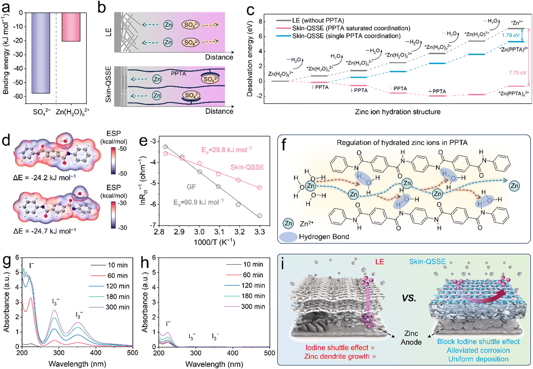
Based on the finite element method (FEM), a microzone model was established to analyze the electric field distribution, current density distribution and concentration field by COMSOL Multiphysics.46 The asymmetric skin-QSSE was simplified to a bilayer structure containing a gel layer and a porous channel layer. However, the high ionic conductivity based on the skin-QSSE produced a uniform electric field and current density distribution that guided uniform and rapid Zn deposition and stripping (Fig. 2j and l). In addition, the Zn2+ concentration field confirmed that the skin-QSSE facilitated a more uniform Zn ion flux compared to that in the LE (Fig. S14, ESI†). The results of COMSOL simulations implied that the ordered COF nano-channels and aramid fibers acted as ion pumps to optimize the ion diffusion kinetics and reduce the concentration polarization at the anode interface.Theoretical calculations and simulations were utilized to further analyze the special mechanism of the COF nanolayer and PPTA hydrogel layer within the asymmetric skin-QSSE. Microscopic solvated structures on the electrode–electrolyte phase interface were investigated at the molecular/atomic level using density functional theory (DFT). Based on binding energy calculations, the interactions between the PPTA aramid fiber chain and SO42− (ΔE = −57.7 kJ mol−1) are stronger than those with Zn(H2O)52+ (ΔE = −20.5 kJ mol−1), indicating a powerful obstruction to SO42− diffusion (Fig. 3a and Fig. S19, ESI†). According to Sand's model, as Zn deposition proceeds, the continuous reduction in salt concentration near the Zn anode leads to strong space charge effects, causing severe dendrite formation (Fig. 3b).47 Compared to the LE environment, the concentration polarization at the anode–electrolyte interface was attenuated due to the immobilization of SO42− anions by PPTA, thus mitigating the growth of dendrites.
 | ||
| Fig. 3 Theoretical calculation and mechanism investigation for the skin-QSSE. (a) Binding energies of SO42− and Zn(H2O)52+ on PPTA. (b) Migration behavior of Zn ions and SO42− in different electrolytes. (c) Desolvation energies for the removal of H2O molecules on Zn(H2O)62+ in LE (without PPTA) and skin-QSSE (with PPTA). (d) Binding energies and ESP distributions of H2O on the amide groups (–CO–NH–) of PPTA. (e) Arrhenius curves and desolvation activation energies (Ea) of the LE and skin-QSEE. (f) Schematic illustration of the migration of hydrated Zn2+ inside skin-QSSE nanofibers. UV-Vis absorption spectra of the right chamber of H-type glass cell with (g) LE and (h) skin-QSSE. (i) Mechanism diagram of the skin-QSSE for both anode and cathode regulation. | ||
In aqueous electrolytes, Zn2+ ions are surrounded by water molecules to form solvated Zn2+, which are associated closely with Zn passivation caused by side reactions and corrosion.48 Reducing the content of solvated [Zn(H2O)6]2+ and controlling the formation of active free water near the Zn anode are effective strategies to enhance the corrosion resistance of Zn foil. For the LE, the desolvation energies of hydrated Zn2+ for the dehydration process continuously increased, with the barrier reaching up to 7.09 eV from Zn(H2O)62+ to Zn2+, as shown in Fig. 3c and Fig. S16 (ESI†). In contrast, the amide (–CO–NH–) groups on the PPTA molecular chain are capable of lowering the desolvation energies during the Zn deposition process. Limited by the spatial steric hindrance of the PPTA molecular chain, Zn ions can maximally coordinate with four PPTA molecules. As depicted in Fig. 3c and Fig. S17 (ESI†), the desolvation energies gradually decreased with the introduction of:
| PPTA (Zn(H2O)62+ → Zn(H2O)5(PPTA)2+: −0.15 eV; |
| Zn(H2O)5(PPTA)2+ → Zn(H2O)4(PPTA)22+: −0.43 eV; |
| Zn(H2O)4(PPTA)22+ → Zn(H2O)3(PPTA)32+: −1.00 eV; |
| Zn(H2O)3(PPTA)32+ → Zn(H2O)2(PPTA)42+: −0.40 eV. |
The desolvation energy from Zn(H2O)62+ to Zn2+ influenced by PPTA is −0.66 eV, which implies that the Zn(H2O)62+ was endowed with the ability of spontaneous dehydration in the skin-QSSE. In addition, only one PPTA was controlled to coordinate with the Zn2+ to further understand the ability of PPTA to reduce the desolvation energy (Fig. S18, ESI†). Despite only a single PPTA molecule coordinating with Zn2+, the energy barrier for each step of the dehydration reaction was significantly reduced compared to the LE (without PPTA). The facile desolvation procedure initiated by PPTA is pivotal for the mitigation of dendrite growth and side reactions at the electrode–electrolyte interface. The binding energies of −24.2 and −24.7 kJ mol−1 between the N and O sites on the amide bonds of the PPTA molecular chain and water molecules suggest that PPTA might lower the Zn desolvation energy by capturing water through hydrogen bonding (Fig. 3d). Additionally, the desolvation activation energy (Ea) in the skin-QSSE was calculated from the Arrhenius curves to be 29.8 kJ mol−1, which was nearly half that of the LE (60.9 kJ mol−1), consistent with the DFT calculation results (Fig. 3e and Fig. S15, ESI†). Consequently, the migration behavior of hydrated Zn2+ within PPTA nanofibers is illustrated schematically in Fig. 3f. As hydrated Zn2+ ions approach the PPTA fibers, water molecules are trapped by hydrogen bonding interaction with the amide bonds, allowing the Zn2+ ions to rapidly transfer along the nanofiber network.
The study mentioned above proved that the skin-QSSE is favorable for Zn anode regulation, but the effect of TFB-TAPT nanolayers on the behavior of the iodine shuttle effect was also required to be evaluated. The diffusion control contrast of electrolytes on polyiodides was undertaken by a visual diffusion change. Clearly, the GF started diffusion of iodide ions within 10 min, and the right chamber turned brownish at 300 min, indicating a significant amount of I3− shuttling (Fig. S20, ESI†). As shown in Fig. 3g, the UV-visible spectrum of the permeate displayed distinct I− and I3− characteristic peaks. In contrast, UV-visible spectroscopy justified the effective shuttle control of iodide ions by the skin-QSSE, as no characteristic peaks of I3− were observed in the permeate solution (Fig. 3h). On the back side of the skin-QSSE, no characteristic peaks of iodide ions were observed in the XPS spectra after the visual shuttle experiment (Fig. S21, ESI†). In addition, the QSSE without TFB-TAPT nanolayers failed to control the iodide ion shuttle significantly, implying that TFB-TAPT nanolayers in the asymmetric skin-QSSE played a crucial role in diffusion inhibition (Fig. S22, ESI†). Zeta potentials revealed that PPTA hydrogels loaded with TFB-TAPT exhibited low negative charges over a wide pH range (Fig. S23, ESI†). Therefore, the control of iodide ion shuttling was primarily governed by electrostatic repulsion of the negatively charged backbone on TFB-TAPT. The mechanism of optimization for the Zn deposition process and the iodide shuttle suppression by the asymmetric skin-QSSE, composed of TFB-TAPT and PPTA hydrogels, is illustrated in Fig. 3i. Effective iodine-selective blocking was provided by the TFB-TAPT nanolayer via electrostatic repulsion. The PPTA hydrogel mitigates Zn foil corrosion and alleviates dendrite growth by regulating the migration behavior of hydrated Zn2+ and SO42−.
To evaluate the effect of TFB-TAPT on the ion diffusion behavior in the skin-QSSE, MD simulations were performed to visualize ion diffusion and quantify the diffusion rate. A diffusion model containing two layers of TFB-TAPT was established to simulate the iodide cathode interface, including 88 SO42−, 88 Zn2+, 16 I−, 16 I3−, and 1800 H2O molecules. Fig. 4a shows a snapshot of the MD simulation configuration at 0 ns, where iodide ions and ZnSO4 are concentrated on the left side of the COF layer. Obviously, as random configuration proceeds to 12 ns, Zn2+ ions predominantly enter TFB-TAPT and diffuse to the right side, while polyiodide ion anions are selectively blocked by the COF layer. The diffusion coefficients of various ions were quantified by mean squared displacements (MSDs) versus time curves. In the TFB-TAPT nanochannels, the diffusion coefficient of Zn2+ was as high as 1.19 Å2 ps−1, which is significantly higher than the diffusion coefficients of I3− (0.14 Å2 ps−1) and I− (0.05 Å2 ps−1) ions (Fig. 4b). As illustrated in Fig. S24 (ESI†), the radial distribution functions (RDFs) of Zn2+, I− and I3− for the triazine groups on the TFB-TAPT skeleton were calculated. In contrast to Zn2+, the RDF peaks of I− and I3− are more prominent, suggesting strong interaction with TFB-TAPT leading to blocked diffusion.
 | ||
| Fig. 4 Performance evaluation of Zn–I2 batteries with the skin-QSSE. (a) The snapshot extracted from the MD simulations of the ion transport behavior in TFB-TAPT nanolayers at 0 ns (left), 12 ns (right). The white atoms are H, the blue atoms are N, the grey atoms are C, the red atoms are O, the yellow atoms are S, the brown atoms are I and the pink atoms are Zn. (b) Time-dependent mean squared displacements (MSDs) of ions in TFB-TAPT. (c) The cyclic voltammetry (CV) curves and (d) log-linear relationship of oxidation and reduction peak currents versus scan rates of Zn–I2 batteries with the skin-QSSE at different scan rates. (e) Rate performance of Zn–I2 batteries with the LE and skin-QSSE at different C-rates. (f) Long-term cycling performance for Zn–I2 batteries with the LE and skin-QSSE at 5C (1C = 0.211 A g−1). (g) The galvanostatic charge–discharge (GCD) curves of the Zn–I2 batteries assembled by the QSSE and LE at 5C. (h) Long-term cycling performance for Zn–I2 batteries with the skin-QSSE at 10C. (i) Comparison of cycling and capacity decay rate performance over other advanced Zn–I2 batteries (circle diameter represents C-rates, see Table S1, for detailed parameters, ESI†). | ||
Performance evaluation of Zn–I2 batteries with the skin-QSSE
A Zn–I2 full battery was assembled to demonstrate the electrochemical performance of the asymmetric skin-QSSE. An iodine cathode was constructed using active carbon (AC) as the host. The BET specific surface area of I2@AC decreased significantly, proving that iodine occupied the pores of the AC, confirming the successful loading of iodine (Fig. S25, ESI†). The iodine loading of the active materials in the cathode was determined by thermogravimetric analysis (TGA, Fig. S26, ESI†). The cyclic voltammetry (CV) curves displayed a pair of oxidation–reduction peaks corresponding to the typical two-electron reaction between I2 and I−/I3− (Fig. S27, ESI†). The lower potential difference between the redox peaks and larger current of the skin-QSSE compared to the LE implied low polarization and remarkable redox kinetics.49 The voltage gap between the reduction and oxidation peaks gradually widened when the scan rate ranged from 0.1 to 0.6 mV s−1 (Fig. 4c and Fig. S28, ESI†). A log-linear relationship between the peak current values and scan rate was obtained according to the equation i = avb as illustrated in Fig. 4d. The calculated anodic peak and cathodic peak b values were 0.89 and 0.88 for the skin-QSSE and LE, respectively, both falling within the range of 0.5–1. This suggests that the electrochemical reaction for Zn–I2 batteries is jointly controlled by ion diffusion and pseudocapacitance.50The rate performance of full-batteries at different C-rates was used to fully evaluate the benefits of the skin-QSSE for the LE. Across the range of 0.5C to 25C rates, full batteries equipped with the skin-QSSE exhibited consistently superior specific capacities (Fig. 4e). Even when the C-rate decreases from 25 to 0.5C, the specific capacity recovers to 190.1 mA h g−1, demonstrating high reversibility. Furthermore, the flat discharge voltage platform for the skin-QSSE at high C-rates from the GCD curves meant fast electrochemical reaction kinetics (Fig. S29, ESI†).51 A full battery assembled using the QSSE without the TFB-TAPT nanolayer was employed to further analyze the role of an asymmetric skin-QSSE bilayer structure (Fig. S30, ESI†). The specific capacity of the Zn–I2 batteries without TFB-TAPT was decreased compared to batteries utilizing the skin-QSSE, due to the dominant role of the COF nanolayer in the inhibition of iodide ion shuttling.
Owing to the skin-QSSE promoting uniform Zn plating/stripping and inhibiting the iodine shuttle, the assembled Zn–I2 battery demonstrates ultra-stable long-term cycling performance. As presented in Fig. S31 (ESI†), the initial specific capacity of the skin-QSSE-assembled battery is as high as 201.5 mA h g−1 at 0.5C, which is approaching the theoretical capacity (211 mA h g−1).52 At high C-rates (5C), 99.9% coulombic efficiency (CE) is still guaranteed and the capacity decay rate was calculated to be 0.0072‰ after 15000 cycles (Fig. 4f) for the skin-QSSE. Notably, quite stable charging/discharging plateaus were maintained at 7500th and 15000th cycles, which were revealed from the GCD curves (Fig. 4g). In contrast, Zn–I2 batteries with the LE exhibited lower initial capacity and significant capacity decay within 1300 cycles due to the excessive iodine shuttle. Comparative analysis of previously reported Zn–I2 batteries based on the separator and electrolyte demonstrated the superior performance of our designed asymmetric skin-QSSE (Fig. 4i, see Table S1 (ESI†) for detailed parameters). Specifically, Zn–I2 batteries with the skin-QSSE in our work demonstrated an ultra-stable cycling performance, with a capacity decay rate of only 0.0018‰ over 45000 cycles at 10C, which is superior to the reported state-of-the-art Zn–I2 batteries (Fig. 4h).
The post-cycling skin-QSSE was systematically characterized to verify its integrity and structural stability under repeated charge/discharge processes. The optical image of the skin-QSSE after 100 h of cycling indicates that it retains its integrity (inset of Fig. S32, ESI†). SEM images reveal that the skin-QSSE maintains its surface structure without visible cracks, indicating robust mechanical integrity after prolonged cycling (Fig. S32, ESI†). FT-IR and XPS analyses of the post-cycling skin-QSSE were performed to evaluate the structural stability and potential degradation risks. The characteristic peaks at 1642 and 1540 cm−1 of the used skin-QSSE are attributed to the stretching vibration of –CO, along with the coupled –N–H bending signal and –C–N stretching vibration (Fig. S33, ESI†).53 This indicates that the amide bonds (–CO–NH–) of PPTA are still present after cycling, demonstrating its excellent structural stability.
XPS was used to further investigate the structural changes of the asymmetric skin-QSSE on the COF side and PPTA side before and after cycling. The PPTA side faces the Zn anode, undergoing issues such as dendrite growth and corrosion at the anode interface. The high-resolution XPS spectra of the PPTA side of the used skin-QSSE were consistent with those of the initial skin-QSSE, with no formation or disappearance of chemical bonds (Fig. S34, ESI†). This suggests that the amide-linked PPTA provides high electrochemical stability.
For the COF side, the TFB-TAPT nanolayer suppresses iodine shuttling at the cathodic interface. Notably, the high-resolution N 1s spectrum shows a new peak at 401.7 eV, which is attributed to the N–I species (Fig. S35, ESI†).54,55 This is due to the interaction of I− with the TFB-TAPT nanolayer, where the I− anion bonds with the N through an ionic bond.56 In addition, the characteristic peak of the CN bond for the TFB-TAPT is evident at 398.7 eV, confirming the high chemical stability of imine-linked COFs in the charge/discharge cycle.
More importantly, fast self-discharge deriving from cross-migration of soluble polyiodides in aqueous media for Zn–I2 batteries, ultimately leading to low specific capacity and reduced Coulombic efficiency.57 As depicted in Fig. 5a, the batteries using LE retained only 66.8% of their initial capacity after 48 h of resting. Thanks to the excellent suppression of iodide ion shuttling by TFB-TAPT nanolayers, the capacity retention of skin-QSSE-assembled batteries was enhanced to 85.0% after 48 h of resting (Fig. 5b). The rapid advancement of electronic devices has underscored the urgent requirement for secondary batteries capable of fast-charging and slow-discharging. The Zn–I2 batteries with skin-QSSEs display a distinct discharge voltage plateau at a high charging rate of 5C and a low discharge rate of 0.5C (Fig. 5c). As depicted in Fig. 5d, the battery demonstrates a high initial specific capacity of 164.6 mA h g−1 and maintains a stable CE (99.7% at the 600th cycle). Additionally, the GCD curves revealed that flat discharging plateaus were maintained at the 2nd, 100th, 300th and 600th cycles, indicating stable Zn ion transport in terms of fast-charging–slow-discharging processes (Fig. S36, ESI†).
 | ||
| Fig. 5 Performance of the Zn–I2 pouch batteries. Self-discharge performance of the Zn–I2 batteries with (a) LE and (b) skin-QSSE. (c) The voltage–time curves of fast-charging and slow-discharging processes. (d) Fast-charging and slow-discharging cycle performance of the Zn–I2 batteries assembled by the skin-QSSE. (e) Schematic diagram of the Zn–I2 pouch batteries with the skin-QSSE. (f) Cycling performance of the Zn–I2 batteries with the skin-QSSE and (g) the galvanostatic charge–discharge (GCD) curves (1 × 2 cm2 of iodine cathode). (h) Bending and cutting experiments on the Zn–I2 pouch batteries. (i) Optical photograph of pouch batteries with the skin-QSSE in series power a timer. | ||
Taking advantage of the flexibility of ANF hydrogels, Zn–I2 pouch batteries were assembled with multiple layers of Zn foil, skin-QSSE, and iodine cathode to explore their practical applications, as depicted in Fig. 5e. The digital photograph of the Zn–I2 pouch battery with the skin-QSSE is shown in Fig. S37 (ESI†). Pouch batteries exhibited an initial capacity of 119.0 mA h g−1 at 0.5C and 99.9% CE for the 300th cycle (Fig. 5f), indicating excellent iodine retention by the skin-QSSE. GCD curves implied that obvious discharging plateaus were maintained at the 1st, 100th and 300th cycles (Fig. 5g). The flexibility of Zn–I2 pouch batteries with skin-QSSEs was further examined by physical bending folding. No significant voltage fluctuations were observed after folding the pouches into 90° and 180°, and the voltage was maintained even after being cut (Fig. 5h). Furthermore, series-connected pouch batteries with skin-QSSEs provided stable power to a timer, further demonstrating their practicality (Fig. 5i).
Material cost analysis of skin-QSSEs is necessary to evaluate their prospects for large-scale energy storage applications. The commercial PPTA fibers have a lower cost, while the cost of skin-QSSEs mainly comes from the DMSO and COF monomers (Table S2, ESI†). As shown in Fig. S38 (ESI†), the cost of skin-QSSEs was calculated to be about 183.15 USD per m2, which is lower than those of commercial GF (284 USD per m2) and Nafion (∼1700 USD per m2) used in the LE. Considering the recyclability of the DMSO solvent and the scalable preparation process of the skin-QSSE, its actual cost may not exceed its material cost. This cost analysis indicates that skin-QSSEs are cost-competitive and have potential commercial viability.
Conclusions
In summary, inspired by the exquisite structure of human skin, we have designed an asymmetric skin-QSSE for ultra-durable Zn–I2 batteries. Relying on the multifunctional structure of TFB-TAPT nanolayers and PPTA hydrogels in the skin-QSSE, ionic migration behavior at the interface of the anode and cathode was significantly improved. DFT calculations confirmed that the desolvation of hydrated Zn2+ was thermodynamically favorable in the skin-QSSE (−0.66 eV of desolvation energy vs. 7.09 eV for LE), implying that the Zn–anode side reactions are weakened. From the MSD curves, the diffusion coefficient of Zn2+ ions (1.19 Å2 ps−1) was significantly higher than those of I3− ions (0.14 Å2 ps−1) and I− ions (0.05 Å2 ps−1) in TFB-TAPT nano-channels, implying that polyiodide ions were selectively blocked. As proof, the Zn–I2 batteries with skin-QSSEs exhibited a high specific capacity (201.5 mA h g−1) at 0.5C, a prolonged cycling lifetime (45000 cycles) and a superior capacity decay rate (0.0018‰) at 10C. The remarkable improvement in electrochemical performance underlines the promise of the skin-QSSE strategy for advanced aqueous iodine-based energy storage systems.
Author contributions
Conceptualization: S. C. C.; methodology: S. C. C., A. W. Z. and B. J. F.; investigation: S. C. C., Y. S. L., L. L. M. and W. Y. L.; writing – original draft: S. C. C. and Y. S. L.; writing – review & editing: S. C. C., Y. S. L., P. S. Y., S. H., Z. H. R., L. L. M. and W. Y. L.; funding acquisition: J. F. S.; resources: J. F. S. and M. X. Y.; and supervision: J. F. S., M. X. Y. and H. Y. F.Data availability
The data supporting this article have been included as part of the ESI.†Conflicts of interest
There are no conflicts to declare.Acknowledgements
This work was financially supported by the National Natural Science Foundation of China (52222315).Notes and references
- C. Xie, C. Wang, Y. Xu, T. Li, Q. Fu and X. Li, Nat. Energy, 2024, 9(6), 714–724 CrossRef CAS.
- Y. Kang, G. Chen, H. Hua, M. Zhang, J. Yang, P. Lin, H. Yang, Z. Lv, Q. Wu, J. Zhao and Y. Yang, Angew. Chem., Int. Ed., 2023, 62, e202300418 CrossRef CAS.
- Y. Liang and Y. Yao, Nat. Rev. Mater., 2023, 8, 109–122 CrossRef.
- L. Jiang, S. Han, Y.-C. Hu, Y. Yang, Y. Lu, Y.-C. Lu, J. Zhao, L. Chen and Y.-S. Hu, Nat. Energy, 2024, 9(7), 839–848 CrossRef CAS.
- Y. Yuan, J. Yang, Z. Liu, R. Tan, M. Chuai, J. Sun, Y. Xu, X. Zheng, M. Wang, T. Ahmad, N. Chen, Z. Zhu, K. Li and W. Chen, Adv. Energy Mater., 2022, 12, 2103705 Search PubMed.
- L. Su, F. Lu, Y. Li, Y. Wang, X. Li, L. Zheng and X. Gao, ACS Nano, 2024, 18(10), 7633–7643 CrossRef CAS PubMed.
- Z. Hou, Y. Gao, H. Tan and B. Zhang, Nat. Commun., 2021, 12, 3083 CrossRef CAS.
- D. Lin and Y. Li, Adv. Mater., 2022, 34, 2200444 CrossRef PubMed.
- W. Wang, C. Li, S. Liu, J. Zhang, D. Zhang, J. Du, Q. Zhang and Y. Yao, Adv. Energy Mater., 2023, 13, 2300250 CrossRef CAS.
- G. Liang, B. Liang, A. Chen, J. Zhu, Q. Li, Z. Huang, X. Li, Y. Wang, X. Wang, B. Xiong, X. Jin, S. Bai, J. Fan and C. Zhi, Nat. Commun., 2023, 14, 1856 CrossRef CAS PubMed.
- K. K. Turekian and K. H. Wedepohl, Geol. Soc. Am. Bull., 1961, 72, 175–192 CrossRef CAS.
- G. W. Meijer, G. Kanny and J. F. Briois, Wiley Interdiscip. Rev.: RNA, 2000, 471 Search PubMed.
- L. Zhang, J. Huang, H. Guo, L. Ge, Z. Tian, M. Zhang, J. Wang, G. He, T. Liu, J. Hofkens, D. J. L. Brett and F. Lai, Adv. Energy Mater., 2023, 13, 2203790 CrossRef CAS.
- X. Li, N. Li, Z. Huang, Z. Chen, G. Liang, Q. Yang, M. Li, Y. Zhao, L. Ma, B. Dong, Q. Huang, J. Fan and C. Zhi, Adv. Mater., 2021, 33, 2006897 CrossRef CAS PubMed.
- Y. Kang, G. Chen, H. Hua, M. Zhang, J. Yang, P. Lin, H. Yang, Z. Lv, Q. Wu, J. Zhao and Y. Yang, Angew. Chem., Int. Ed., 2023, 62, e202300418 CrossRef CAS PubMed.
- Z. Hu, X. Wang, W. Du, Z. Zhang, Y. Tang, M. Ye, Y. Zhang, X. Liu, Z. Wen and C. C. Li, ACS Nano, 2023, 17, 23207–23219 CrossRef CAS PubMed.
- X. Yang, H. Fan, F. Hu, S. Chen, K. Yan and L. Ma, Nano-Micro Lett., 2023, 15, 126 CrossRef CAS PubMed.
- L. Chai, X. Wang, Y. Hu, X. Li, S. Huang, J. Pan, J. Qian and X. Sun, Adv. Sci., 2022, 9, e2105063 CrossRef PubMed.
- T. Geng, S. Ye, Z. Zhu and W. Zhang, J. Mater. Chem. A, 2018, 6, 2808–2816 RSC.
- J. Hu, Z. Zhang, T. Deng, F. C. Cui, X. Shi, Y. Tian and G. Zhu, Adv. Mater., 2024, 36(29), e2401091 CrossRef PubMed.
- Y. Zhao, Y. Wang, W. Xue, R. Cheng, X. Zheng, G. Zhu, D. Hu, H. Huang, C. Hu and D. Liu, Adv. Mater., 2024, 36, 2403097 CrossRef CAS PubMed.
- S. Huang, R. Tang, X. Liu, Y. Zhang, Y. Tang, Z. Wen, M. Ye, Y. Yang and C. C. Li, Energy Environ. Sci., 2024, 17, 591–601 RSC.
- F. Wang, W. Liang, X. Liu, T. Yin, Z. Chen, Z. Yan, F. Li, W. Liu, J. Lu, C. Yang and Q. H. Yang, Adv. Energy Mater., 2024, 14, 2400110 CrossRef CAS.
- Y. Yang, S. Liang, B. Lu and J. Zhou, Energy Environ. Sci., 2022, 15, 1192–1200 RSC.
- J. L. Yang, Z. Yu, J. Wu, J. Li, L. Chen, T. Xiao, T. Xiao, D. Q. Cai, K. Liu, P. Yang and H. J. Fan, Adv. Mater., 2023, 35, e2306531 CrossRef PubMed.
- K. K. Sonigara, J. Zhao, H. K. Machhi, G. Cui and S. S. Soni, Adv. Energy Mater., 2020, 10, 2001997 CrossRef CAS.
- F. Wu, Y. Ren, W. Lv, X. Liu, X. Wang, C. Wang, Z. Cao, J. Liu, J. Wei and Y. Pang, Nat. Commun., 2024, 15, 802 CrossRef CAS PubMed.
- B. Ying and X. Liu, iScience, 2021, 24, 103174 CrossRef PubMed.
- T. A. Harris-Tryon and E. A. Grice, Science, 2022, 376, 940–945 CrossRef CAS PubMed.
- M. Wang, Y. Luo, T. Wang, C. Wan, L. Pan, S. Pan, K. He, A. Neo and X. Chen, Adv. Mater., 2021, 33, 2003014 CrossRef CAS PubMed.
- J. Zhu, M. Yang, A. Emre, J. H. Bahng, L. Xu, J. Yeom, B. Yeom, Y. Kim, K. Johnson, P. Green and N. A. Kotov, Angew. Chem., Int. Ed., 2017, 56, 11744–11748 CrossRef CAS PubMed.
- Y. Yang, H. Hua, Z. Lv, W. Meng, M. Zhang, H. Li, P. Lin, J. Yang, G. Chen, Y. Kang, Z. Wen, J. Zhao and C. C. Li, ACS Energy Lett., 2023, 8, 1959–1968 CrossRef CAS.
- S. Cao, J. Tan, L. Ma, Y. Liu, Q. He, W. Lu, Z. Liu, M. Ye and J. Shen, Energy Storage Mater., 2024, 66, 103232 CrossRef.
- A. Knebel and J. Caro, Nat. Nanotechnol., 2022, 17, 911–923 CrossRef CAS PubMed.
- C. Kang, Z. Zhang, V. Wee, A. K. Usadi, D. C. Calabro, L. S. Baugh, S. Wang, Y. Wang and D. Zhao, J. Am. Chem. Soc., 2020, 142, 12995–13002 CrossRef CAS PubMed.
- A. Zhang, J. Zhu, S. Han, Y. Zhang and B. Van der Bruggen, J. Membr. Sci., 2022, 662, 120987 CrossRef CAS.
- T. Wei, L. e Mo, Y. Ren, H. Zhang, M. Wang, Y. He, P. Tan, Z. Li, W. Chen and L. Hu, Energy Storage Mater., 2024, 70, 103525 CrossRef.
- J. Xu, S. An, X. Song, Y. Cao, N. Wang, X. Qiu, Y. Zhang, J. Chen, X. Duan, J. Huang, W. Li and Y. Wang, Adv. Mater., 2021, 33, 2105178 CrossRef CAS PubMed.
- X. Kong, Z. Wu, M. Stromme and C. Xu, J. Am. Chem. Soc., 2024, 146, 742–751 Search PubMed.
- L. Bai, Q. Gao and Y. Zhao, J. Mater. Chem. A, 2016, 4, 14106–14110 Search PubMed.
- X. Zhao, Q. Li, P. Pachfule, Z. Wang, S. Liu, W. Wu, M. Wu and A. Thomas, Small, 2023, 19, 2301200 CrossRef CAS PubMed.
- Z. Mu, Y. Zhu, Y. Zhang, A. Dong, C. Xing, Z. Niu, B. Wang and X. Feng, Angew. Chem., Int. Ed., 2023, 62, e202300373 Search PubMed.
- Y.-N. Lu, K. Mo, X.-H. Liang, J.-S. Xie, Y. Yang, L. Zheng, M. Gu, X.-R. Liu, Y. Lu and J. Ge, ACS Appl. Mater. Interfaces, 2024, 16, 60992–61003 Search PubMed.
- S. Yang, Y. Zhang, Y. Zhang, J. Deng, N. Chen, S. Xie, Y. Ma and Z. Wang, Adv. Funct. Mater., 2023, 33, 2304280 Search PubMed.
- P. Lin, G. Chen, Y. Kang, M. Zhang, J. Yang, Z. Lv, Y. Yang and J. Zhao, ACS Nano, 2023, 17, 15492–15503 CrossRef CAS PubMed.
- K. Zhu, L. Wu, C. Guo, J. Pu, Y. Liu, X. Chen, Y. Chen, P. Xue, J. Han and Y. Yao, Adv. Funct. Mater., 2023, 33, 2305098 CrossRef CAS.
- J. L. Yang, T. Xiao, T. Xiao, J. Li, Z. Yu, K. Liu, P. Yang and H. J. Fan, Adv. Mater., 2024, 36(21), e2313610 Search PubMed.
- M. Li, Z. Li, X. Wang, J. Meng, X. Liu, B. Wu, C. Han and L. Mai, Energy Environ. Sci., 2021, 14, 3796–3839 Search PubMed.
- C. Guo, Y. Cao, Y. Gao, C. Zhi, Y. X. Wang, Y. Luo, X. J. Yang and X. Luo, Adv. Funct. Mater., 2024, 34, 2314189 CrossRef CAS.
- Y. Su, X. Wang, M. Zhang, H. Guo, H. Sun, G. Huang, D. Liu and G. Zhu, Angew. Chem., Int. Ed., 2023, 62, e202308182 CrossRef CAS PubMed.
- H. Xu, R. Zhang, D. Luo, J. Wang, H. Dou, X. Zhang and G. Sun, ACS Nano, 2023, 17, 25291–25300 CrossRef CAS PubMed.
- J. L. Yang, H. H. Liu, X. X. Zhao, X. Y. Zhang, K. Y. Zhang, M. Y. Ma, Z. Y. Gu, J. M. Cao and X. L. Wu, J. Am. Chem. Soc., 2024, 146(10), 6628–6637 CrossRef CAS PubMed.
- L. Yang, Y. J. Zhu, H. P. Yu, Z. Y. Wang, L. Cheng, D. D. Li, J. Tao, G. He and H. Li, Adv. Energy Mater., 2024, 14, 2401858 Search PubMed.
- X. Li, J. Yu, W. Li, Y. Liao, M. Li, B. Zhao, X. Liu, S. Huang, S. Xia, J. Zhang and Y. Jiang, Chem. Eng. J., 2025, 505, 159355 CrossRef CAS.
- M. Wang, Y. Meng, M. Sajid, Z. Xie, P. Tong, Z. Ma, K. Zhang, D. Shen, R. Luo, L. Song, L. Wu, X. Zheng, X. Li and W. Chen, Angew. Chem., Int. Ed., 2024, 63, e202404784 Search PubMed.
- X. Li, Y. Wang, Z. Chen, P. Li, G. Liang, Z. Huang, Q. Yang, A. Chen, H. Cui, B. Dong, H. He and C. Zhi, Angew. Chem., Int. Ed., 2022, 61, e202113576 Search PubMed.
- H. Wang, X. Liu, J. Zhong, L. Du, S. Yun, X. Zhang, Y. Gao and L. Kang, Small, 2024, 20, 2306947 CrossRef CAS PubMed.
Footnote |
| † Electronic supplementary information (ESI) available. See DOI: https://doi.org/10.1039/d4ee05527f |
| This journal is © The Royal Society of Chemistry 2025 |