 Open Access Article
Post-synthetic modification of covalent organic frameworks with active manganese centers for electrocatalytic CO2 reduction in water†
Elena
Gala‡
 ab,
Geyla
C. Dubed Bandomo‡
c,
Mattia
Vettori
c,
Sergio
Royuela
 d,
Marcos
Martínez-Fernández
 a,
José I.
Martínez
 e,
Elena
Salagre
 fg,
Enrique G.
Michel
 fg,
Félix
Zamora
 dgh,
Julio
Lloret-Fillol
 *ci and
José L.
Segura
 *a
*a
aDepartamento de Química Orgánica I, Facultad de CC. Químicas, Universidad Complutense de Madrid, 28040 Madrid, Spain. E-mail: segura@ucm.es
bChemical and Environmental Technology Department, Rey Juan Carlos University, Móstoles, 28933, Spain
cInstitute of Chemical Research of Catalonia (ICIQ), The Barcelona Institute of Science and Technology, Tarragona 43007, Spain. E-mail: jlloret@iciq.es
dDepartamento de Inorgánica, Facultad de Ciencias, Universidad Autónoma de Madrid, Campus de Cantoblanco – Crta. Colmenar, Madrid 28049, Spain
eDepartamento de Materiales de baja dimensionalidad, Instituto de Ciencia de Materiales de Madrid (ICMM-CSIC), 28049 Madrid, Spain
fDepartamento de Física de la Materia Condensada, Universidad Autónoma de Madrid, 28049, Madrid, Spain
gCondensed Matter Physics Center (IFIMAC), Universidad Autónoma de Madrid, 28049, Madrid, Spain
hInstitute for Advanced Research in Chemical Sciences (IAdChem), Universidad Autónoma de Madrid, Campus de Cantoblanco, Madrid 28049, Spain
iCatalan Institution for Research and Advanced Studies (ICREA), Barcelona 08010, Spain
First published on 26th November 2024
Abstract
The development of effective catalysts for the CO2 reduction reaction (CO2RR) is essential for transforming atmospheric CO2 into valuable chemical scaffolds. While numerous catalysts have been developed for the CO2RR, few are suitable for use in aqueous systems due to inherent design challenges. In this context, Covalent Organic Frameworks (COFs) have emerged as promising materials for the CO2RR in water, offering potential solutions to these challenges. Thanks to their porosity, high surface area and crystalline structure, COFs are excellent hosts for single-atom catalysts (SACs), enabling the immobilization of high-value species and their utilization in heterogeneous catalytic processes. For this reason, we have explored the catalytic activity of a terpyridine–manganese complex integrated into a COF lattice, which was successfully synthesized and characterized, confirming the presence of the metal ion in the material with spectroscopic techniques such as XPS and EDS. This new material has proved to be an active heterogeneous catalyst for the CO2RR in water as solvent, achieving a faradaic yield of 42% for CO at 300 mV overpotential and 16% for formate when 600 mV was applied. Furthermore, an ab initio theoretical study was performed to provide a plausible mechanism of the CO2RR to elucidate the CO evolution pathway.
Introduction
CO2 has become a target molecule to use as a C1 building block to synthesize high-value renewable solar fuels in the context of circular economy.1–3 The electrocatalytic reduction of CO2 (CO2RR) to valuable products such as liquid fuels can not only reduce CO2 accumulation in the atmosphere but also lead to pathways toward new renewable chemicals and high energy density fuels.4 Careful design of catalysts for this transformation has delivered molecular complexes with extremely high turnover frequencies, and in many cases low onset potentials, for C1 products such as CO, HCOOH and CH4.5,6 Despite these advances, the majority of studies involve catalysts only soluble in organic solvents – a reaction medium that also facilitates high CO2 concentrations. In contrast, heterogeneous catalysts including metals such as Cu, Au and Ag offer high current densities and stability in water, but rational design of the catalyst sites and development of catalysts remain significant challenges.7 This gap underscores the need for catalyst designs that combine the efficiency and selectivity of molecular complexes with the environmental benefits and operational feasibility of heterogeneous systems.For instance, manganese(I) tricarbonyl complexes are efficient catalysts for the CO2RR to generate CO with good faradaic yields in protic organic media. However, these complexes generally suffer from poor solubility in water and low recyclability. The heterogenization of catalysts has been a long-standing strategy to mitigate these problems, improving the stability of molecular catalysts that operate in the homogeneous phase.8–11 To develop efficient (high turnover frequency “TOFmax” and low overpotential “η”) and robust (high turnover number “TON”) [Mn(N^N)(CO)3X]-based catalysts for CO2 reduction, the immobilization in a heterogeneous fashion at a solid-state interface has been explored.12–15 The heterogenization of well-defined catalysts could be prepared by immobilizing them on conducting and semiconducting substrates16–18 and porous polymers,19 among others.20 Some of these strategies to improve the stability of [Mn(N^N)(CO)3X]-based catalysts are included in Fig. 1.13,16–19,21–24
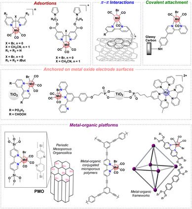 | ||
| Fig. 1 Selected immobilization strategies employed in manganese tricarbonyl complexes containing polypyridyl moieties. | ||
Recently, a number of studies have demonstrated another route using crystalline porous materials: Covalent Organic Frameworks (COFs)25 and Metal–Organic Frameworks (MOFs).26 These frameworks have demonstrated high levels of activity for electrocatalytic CO2 reduction when integrated with molecular electrocatalysts.27–32 The molecular nature of MOF and COF precursors facilitates the incorporation of established molecular catalysts, resulting in frameworks that often outperform their molecular counterparts in terms of efficiency, stability, and durability.25,26
Therefore, the use of MOFs and COFs for catalytic purposes has been extensively explored.33–35 The integration of molecular catalytic units into extended frameworks has often resulted in improved efficiency, stability and durability compared to the corresponding molecular analogues.
Among the potential applications of COFs as catalysts, they stand out especially because they have been shown to be excellent precursors or hosts for single-atom catalysts (SACs).36,37 COFs minimize the sizes of catalytic nanoparticles and, as a result, expose more reactive sites to facilitate mass/electron transfer at the interface and to achieve high catalytic reactivity.38 In this context, the potential application of COFs for the CO2RR has begun to be explored and, as a result, porphyrin, phthalocyanine and bipyridine-based complexes have been integrated as building blocks into COFs or MOFs for the CO2RR.2,29,39–52
Combining the merits of heterogeneous and homogeneous catalysts, reticular chemistry endows the framework materials with high surface areas, porous structures, and potential for rational tailoring for optimizing CO2RR performance.38,53 Such an approach has significant advantages as it provides materials with well-defined, tunable, catalytic sites in a stable heterogenized form. Recently, a new CO2 reduction catalyst by loading single-atom centers, {fac-Mn(CO)3S}, into a bipyridyl-inspired COF with 10 times higher catalytic activity than that obtained for the equivalent manganese-based molecular catalyst and access to key catalytic intermediates within a COF matrix has been published.54
In this context, herein, we report on the synthesis, characterization and electrochemical evaluation for CO2 reduction of a novel fac-[Mn(bpy)(CO)3Br]-terpyridine type 2D COF (Mn@Terpy-COF). The synthesized materials have been characterized by inductively coupled plasma optical emission spectrometry (ICP-OES), thermogravimetric analysis (TGA), infrared spectroscopy (IR), carbon-13 cross-polarization magic angle spinning nuclear magnetic resonance (13C-CP/MAS NMR), scanning electron microscopy-energy dispersive X-ray spectroscopy (SEM-EDX), transmission electron microscopy (TEM), powder X-ray diffraction (PXRD), X-ray photoelectron spectroscopy (XPS) and X-ray absorption spectroscopy (XAS).
Results and discussion
Synthesis and characterization of Terpy-COF
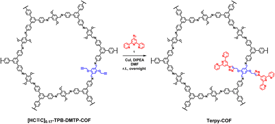
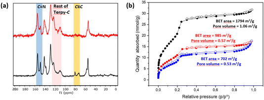
A COF doped with terpyridine moieties, Terpy-COF, has been prepared by covalently linking azidoterpyridine 1 with a COF endowed with reactive alkyne moieties, [HC![[triple bond, length as m-dash]](https://www.rsc.org/images/entities/char_e002.gif) C]0.17-TPB-DMTP-COF,55via a copper catalyzed [3 + 2] cycloaddition reaction (Scheme 1). The structural characterization of the new COF has been elucidated and compared with that of the precursor COF endowed with alkyne moieties. The completeness of the reaction between the azides and the alkyne was confirmed by Fourier transform infrared (FT-IR) spectroscopy (Fig. S5†) and Solid-state Cross-Polarization Magic Angle Spinning Carbon-13 Nuclear Magnetic Resonance (13C-CP/MAS-NMR) (Fig. 2a). Thus, the diagnostic ν(C
C]0.17-TPB-DMTP-COF,55via a copper catalyzed [3 + 2] cycloaddition reaction (Scheme 1). The structural characterization of the new COF has been elucidated and compared with that of the precursor COF endowed with alkyne moieties. The completeness of the reaction between the azides and the alkyne was confirmed by Fourier transform infrared (FT-IR) spectroscopy (Fig. S5†) and Solid-state Cross-Polarization Magic Angle Spinning Carbon-13 Nuclear Magnetic Resonance (13C-CP/MAS-NMR) (Fig. 2a). Thus, the diagnostic ν(C![[double bond, length as m-dash]](https://www.rsc.org/images/entities/char_e001.gif) N) stretching band at 1618 cm−1 remains almost unaltered in the FT-IR spectra after the cycloaddition reaction.56 On the other hand, the 13C-CP/MAS-NMR spectrum evidences the efficient transformation as revealed by the disappearance of the signals corresponding to the alkyne group at 79 and 72 ppm (Fig. 2a). The remaining aliphatic signal at 54 ppm is attributed to the methoxy groups of the COF skeleton. The introduction of the terpyridine fragment was also confirmed by analyzing the aromatic region. First, quaternary pyridine C
N) stretching band at 1618 cm−1 remains almost unaltered in the FT-IR spectra after the cycloaddition reaction.56 On the other hand, the 13C-CP/MAS-NMR spectrum evidences the efficient transformation as revealed by the disappearance of the signals corresponding to the alkyne group at 79 and 72 ppm (Fig. 2a). The remaining aliphatic signal at 54 ppm is attributed to the methoxy groups of the COF skeleton. The introduction of the terpyridine fragment was also confirmed by analyzing the aromatic region. First, quaternary pyridine C![[double bond, length as m-dash]](https://www.rsc.org/images/entities/char_e001.gif) N carbons were localized together with the rest of the C
N carbons were localized together with the rest of the C![[double bond, length as m-dash]](https://www.rsc.org/images/entities/char_e001.gif) N carbons of the COF in the signal at 154 ppm, which appears broader than in the starting material [HC
N carbons of the COF in the signal at 154 ppm, which appears broader than in the starting material [HC![[triple bond, length as m-dash]](https://www.rsc.org/images/entities/char_e002.gif) C]0.17-TPB-DMTP-COF (Fig. S3†). The introduction of the pyridine fragment was not only evidenced by the widening of the signal corresponding to C
C]0.17-TPB-DMTP-COF (Fig. S3†). The introduction of the pyridine fragment was not only evidenced by the widening of the signal corresponding to C![[double bond, length as m-dash]](https://www.rsc.org/images/entities/char_e001.gif) N, but also by the appearance of a new signal (observed as a shoulder) at 117 ppm and enhancement of the relative intensities of signals at 122 and 109 ppm (Fig. S3†), which corresponds to chemical shifts of terpyridine C3′(5′), C3(3′′) and C5(5′′) carbons (Fig. S2 and S4†). The chemical shifts of the rest of the anisochronous nuclei correspond well with those expected for the structure of the COF core, those of the triazole rings and that of the terpyridine system. It should be highlighted that neither the precursor [HC
N, but also by the appearance of a new signal (observed as a shoulder) at 117 ppm and enhancement of the relative intensities of signals at 122 and 109 ppm (Fig. S3†), which corresponds to chemical shifts of terpyridine C3′(5′), C3(3′′) and C5(5′′) carbons (Fig. S2 and S4†). The chemical shifts of the rest of the anisochronous nuclei correspond well with those expected for the structure of the COF core, those of the triazole rings and that of the terpyridine system. It should be highlighted that neither the precursor [HC![[triple bond, length as m-dash]](https://www.rsc.org/images/entities/char_e002.gif) C]0.17-TPB-DMTP-COF nor the final cycloaddition product exhibited FTIR or 13C-CP-MAS-NMR signals of the starting materials corresponding to aldehyde or amine functionalities. The introduction of the terpyridine fragment into the pore resulted, as expected, in a decrease of the Brunauer–Emmett–Teller (BET) surface area of Terpy-COF (985 m2 g−1) in comparison with that of the starting material [HC
C]0.17-TPB-DMTP-COF nor the final cycloaddition product exhibited FTIR or 13C-CP-MAS-NMR signals of the starting materials corresponding to aldehyde or amine functionalities. The introduction of the terpyridine fragment into the pore resulted, as expected, in a decrease of the Brunauer–Emmett–Teller (BET) surface area of Terpy-COF (985 m2 g−1) in comparison with that of the starting material [HC![[triple bond, length as m-dash]](https://www.rsc.org/images/entities/char_e002.gif) C]0.17-TPB-DMTP-COF (1794 m2 g−1) (Fig. 2b). N2 sorption isotherms at 77 K also revealed a reduction of pore volume (from 1.06 cm3 g−1 to 0.57 cm3 g−1 at 0.95 p/p0) and pore size distribution, calculated by NLDFT (Fig. S7†). These data, together with the IV-type isotherm obtained, evidence the mesoporous nature of Terpy-COF.55
C]0.17-TPB-DMTP-COF (1794 m2 g−1) (Fig. 2b). N2 sorption isotherms at 77 K also revealed a reduction of pore volume (from 1.06 cm3 g−1 to 0.57 cm3 g−1 at 0.95 p/p0) and pore size distribution, calculated by NLDFT (Fig. S7†). These data, together with the IV-type isotherm obtained, evidence the mesoporous nature of Terpy-COF.55
Morphological characterization of Terpy-COF and [HC![[triple bond, length as m-dash]](https://www.rsc.org/images/entities/char_e002.gif) C]0.17-TPB-DMTP-COF has been carried out by using Scanning Electron Microscopy (SEM). SEM micrographs revealed that the mild conditions of the copper catalyzed click reaction did not significantly alter the morphology of the COF and therefore [HC
C]0.17-TPB-DMTP-COF has been carried out by using Scanning Electron Microscopy (SEM). SEM micrographs revealed that the mild conditions of the copper catalyzed click reaction did not significantly alter the morphology of the COF and therefore [HC![[triple bond, length as m-dash]](https://www.rsc.org/images/entities/char_e002.gif) C]0.17-TPB-DMTP-COF and Terpy-COF exhibit almost identical rodlike morphologies (Fig. S8 and S9†).
C]0.17-TPB-DMTP-COF and Terpy-COF exhibit almost identical rodlike morphologies (Fig. S8 and S9†).
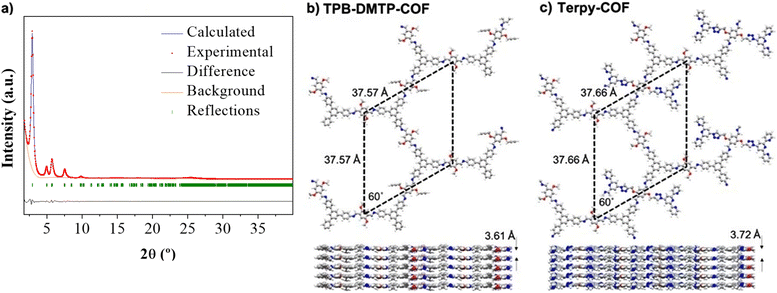
X-ray powder diffraction (PXRD) analysis of Terpy-COF revealed a high degree of crystallinity, with six distinctive diffraction peaks which almost replicate those previously observed for [HC![[triple bond, length as m-dash]](https://www.rsc.org/images/entities/char_e002.gif) C]0.17-TPB-DMTP-COF with an eclipsed AA stacking (Fig. 3a).55 The most intense diffraction maximum, at 2.90°, had an excellent FWHM value of 0.2303° and corresponds to the (100) facet.57 The other peaks appeared at 4.95°, 5.70°, 7.54°, 9.83° and 25.20° and can be assigned to (110), (200), (210), (220) and (001) reflections according to that previously reported for [HC
C]0.17-TPB-DMTP-COF with an eclipsed AA stacking (Fig. 3a).55 The most intense diffraction maximum, at 2.90°, had an excellent FWHM value of 0.2303° and corresponds to the (100) facet.57 The other peaks appeared at 4.95°, 5.70°, 7.54°, 9.83° and 25.20° and can be assigned to (110), (200), (210), (220) and (001) reflections according to that previously reported for [HC![[triple bond, length as m-dash]](https://www.rsc.org/images/entities/char_e002.gif) C]0.17-TPB-DMTP-COF.55 With the aim to confirm the macromolecular crystal structure of Terpy-COF, we have conducted an extensive set of DFT-based calculations using a combination of Gaussian 16 C.01 (ref. 58) and QUANTUM ESPRESSO59 software packages to determine the crystalline structures of TPB-DMTP-COF and Terpy-COF in this study (further computational details in the ESI†). The simulations revealed purely hexagonal symmetry for all crystal structures, with monolayer lattice parameters ranging from 37.57 to 37.72 Å (Fig. 3). We studied the preferred stacking configuration for TPB-DMTP-COF and Terpy-COF. In both cases, the AA eclipsed configuration was found to be preferential, with very similar interlayer distances of 3.61 and 3.72 Å (Fig. 3). The theoretical diffractograms based on optimized crystal structures (Fig. 3c, practically identical for both) showed excellent agreement with experimental ones. The diffraction peaks in the simulated PXRD pattern are located at 2.803°, 4.821°, 5.605°, 7.287°, 13.677° and 24.776° in excellent agreement with the experimental evidence, as shown by Rietveld refinement (Fig. 3a). The simulated PXRD pattern even reproduced high-angle features, confirming the validity of structures obtained from simultaneous structure + cell DFT geometrical optimization.
C]0.17-TPB-DMTP-COF.55 With the aim to confirm the macromolecular crystal structure of Terpy-COF, we have conducted an extensive set of DFT-based calculations using a combination of Gaussian 16 C.01 (ref. 58) and QUANTUM ESPRESSO59 software packages to determine the crystalline structures of TPB-DMTP-COF and Terpy-COF in this study (further computational details in the ESI†). The simulations revealed purely hexagonal symmetry for all crystal structures, with monolayer lattice parameters ranging from 37.57 to 37.72 Å (Fig. 3). We studied the preferred stacking configuration for TPB-DMTP-COF and Terpy-COF. In both cases, the AA eclipsed configuration was found to be preferential, with very similar interlayer distances of 3.61 and 3.72 Å (Fig. 3). The theoretical diffractograms based on optimized crystal structures (Fig. 3c, practically identical for both) showed excellent agreement with experimental ones. The diffraction peaks in the simulated PXRD pattern are located at 2.803°, 4.821°, 5.605°, 7.287°, 13.677° and 24.776° in excellent agreement with the experimental evidence, as shown by Rietveld refinement (Fig. 3a). The simulated PXRD pattern even reproduced high-angle features, confirming the validity of structures obtained from simultaneous structure + cell DFT geometrical optimization.
Synthesis of Mn@Terpy-COF
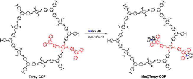
The post-functionalization of Terpy-COF was performed by a direct reaction with Mn(CO)5Br at 45 °C in diethyl ether for 4 h, forming Mn@Terpy-COF as a brown powder (Scheme 2). The amount of Mn measured by inductively coupled plasma-optical emission spectroscopy (ICP-OES) results in an inclusion of 38 mg of Mn per gram of Terpy-COF, which accounted for ∼75% of the COF terpyridines coordinated to Mn after de metalation.The incorporation of {fac-Mn(CO)3Br} fragments into Terpy-COF was confirmed by ATR-FT-IR spectroscopy, showing the presence of two CO stretching frequencies at 2020 cm−1 and a shoulder at 1919 cm−1 (Fig. 4). The frequency at 2020 cm−1 matches the ν(CO) of the symmetric CO vibration of the facial tricarbonyl moiety and the unresolved broad band at 1919 cm−1 corresponds to the symmetric and asymmetric equatorial CO vibration. This pattern is analogous to that shown by the molecular {fac-Mn(I)(κ2-terp)(CO)3Br} complex reported by Kubiak and col.60 UV-vis spectroscopy (Fig. S6†), thermogravimetric analysis (Fig. S14†), PXRD (Fig. S15†) and porosity and surface area measurements (Fig. 2 and S7†) were also conducted to characterize the material. Powder X-ray diffraction analysis confirmed that the crystallinity of the COF was preserved after the metalation process (Fig. S15†). As anticipated, the porosity and surface area decreased following the incorporation of the metal within the pore structure, yielding a BET surface area of 702 m2 g−1 (Fig. 2) and a pore volume of 0.53 cm3 g−1 at a relative pressure of 0.95 (p/p0, Fig. S7†). These observations align with the expected reduction in porosity and pore volume upon introduction of Mn and CO moieties into the pore network, confirming the impact of these modifications on the material's structural properties.
 | ||
| Fig. 4 (a) ATR spectra ν(CO) at 2025 and 1915 (sh) and (b) SEM of Terpy-COF (blue) and Mn@Terpy-COF (red). | ||
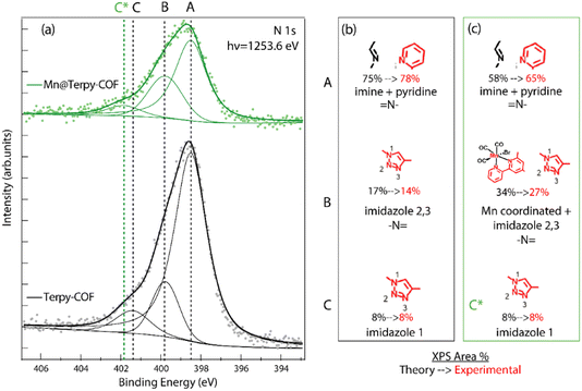
An extensive X-ray photoemission spectroscopy (XPS) characterization study was also performed to confirm the structure assigned to Terpy-COF and Mn@Terpy-COF (Fig. S16–19†). Analyzing first the starting material Terpy-COF, the N 1s emission peak was clearly identified and showed different components, so it was deconvoluted for a more detailed analysis. The two main components, labeled A and B, were identified at 398.5 and 399.9 eV, and an additional minor component, labeled C, was observed at 401.5 eV (Fig. 5). The main component, corresponding to a binding energy of 398.5 eV, was attributed to –N![[double bond, length as m-dash]](https://www.rsc.org/images/entities/char_e001.gif) of the imine and pyridine groups. The peaks detected at 399.9 and 401.5 eV were assigned to imidazole nitrogen atoms. Specifically, the lower binding energy signal was assigned to N, labeled 2 and 3, while the less intense crest was assigned to the nitrogen directly attached to the terpyridine fragment, labeled 1 (Fig. 5). These relative positions of binding energy and intensity percentages agree with our predictions and with data from the literature. The addition of manganese to the COF caused a noticeable change in the N 1s peak area percentages and a slight displacement of the component with the highest binding energy (C) as can be seen in Fig. 5. The observed percentage change of the peak is related to the shift of the binding energy of some of the terpyridine nitrogen atoms from the initial imine region (398.5 eV) to the imidazole 2 and 3 zones at 399.9 eV, where the signal is broader and has a higher relative intensity. This result is consistent with what is expected for the structure of Mn@Terpy-COF because the nitrogens coordinated with manganese have given charge to the metal ion and appear more oxidized. On the other hand, the signal originating from Mn 2p in the Mn@Terpy-COF XPS spectrum shows two components (Fig. S17†). The major component (642 eV, 67%) is assigned to manganese coordinated to terpyridine. The minor component (646 eV, 33%) could be related to manganese in a different environment, but we discard this interpretation considering the high value of the binding energy. Instead, we attribute it to a shake-up satellite observed in other Mn coordination complexes about 4 eV higher than the main Mn 2p photoelectron line.61 In both compounds, Terpy-COF and Mn@Terpy-COF, the C 1s signals are similar (Fig. S18†), with the major component attributed to aromatic sp2 carbons (A label). Minor components were also identified at higher binding energies and were assigned to sp2 carbon directly bonded to nitrogen and oxygen (B label).
of the imine and pyridine groups. The peaks detected at 399.9 and 401.5 eV were assigned to imidazole nitrogen atoms. Specifically, the lower binding energy signal was assigned to N, labeled 2 and 3, while the less intense crest was assigned to the nitrogen directly attached to the terpyridine fragment, labeled 1 (Fig. 5). These relative positions of binding energy and intensity percentages agree with our predictions and with data from the literature. The addition of manganese to the COF caused a noticeable change in the N 1s peak area percentages and a slight displacement of the component with the highest binding energy (C) as can be seen in Fig. 5. The observed percentage change of the peak is related to the shift of the binding energy of some of the terpyridine nitrogen atoms from the initial imine region (398.5 eV) to the imidazole 2 and 3 zones at 399.9 eV, where the signal is broader and has a higher relative intensity. This result is consistent with what is expected for the structure of Mn@Terpy-COF because the nitrogens coordinated with manganese have given charge to the metal ion and appear more oxidized. On the other hand, the signal originating from Mn 2p in the Mn@Terpy-COF XPS spectrum shows two components (Fig. S17†). The major component (642 eV, 67%) is assigned to manganese coordinated to terpyridine. The minor component (646 eV, 33%) could be related to manganese in a different environment, but we discard this interpretation considering the high value of the binding energy. Instead, we attribute it to a shake-up satellite observed in other Mn coordination complexes about 4 eV higher than the main Mn 2p photoelectron line.61 In both compounds, Terpy-COF and Mn@Terpy-COF, the C 1s signals are similar (Fig. S18†), with the major component attributed to aromatic sp2 carbons (A label). Minor components were also identified at higher binding energies and were assigned to sp2 carbon directly bonded to nitrogen and oxygen (B label).
Electrocatalytic CO2 reduction in water with Mn@Terpy-COF
![[thin space (1/6-em)]](https://www.rsc.org/images/entities/char_2009.gif) :
:![[thin space (1/6-em)]](https://www.rsc.org/images/entities/char_2009.gif) 1 mg
1 mg![[thin space (1/6-em)]](https://www.rsc.org/images/entities/char_2009.gif) :
:![[thin space (1/6-em)]](https://www.rsc.org/images/entities/char_2009.gif) 100 μL
100 μL![[thin space (1/6-em)]](https://www.rsc.org/images/entities/char_2009.gif) :
:![[thin space (1/6-em)]](https://www.rsc.org/images/entities/char_2009.gif) 100 μL) by sonication (15 minutes) to obtain the Mn@Terpy-COF|NT|ink catalyst ink. 10 μL of the dispersion were added dropwise onto the electrode surface and allowed to dry in the dark and under ambient conditions to yield Mn@Terpy-COF|NT (Fig. S13) (see ESI for details†).
100 μL) by sonication (15 minutes) to obtain the Mn@Terpy-COF|NT|ink catalyst ink. 10 μL of the dispersion were added dropwise onto the electrode surface and allowed to dry in the dark and under ambient conditions to yield Mn@Terpy-COF|NT (Fig. S13) (see ESI for details†).
To gain insight into the COF matrix and the electronic structure and coordination environment of the Mn centers in the catalyst ink, an XPS study was performed. The XPS analysis of Mn@Terpy-COF|NT|ink suspension and Mn@Terpy-COF|NT showed, as previously described, C 1s signals but with new significantly shifted components, assigned to the carbon atoms bonded to fluorine atoms present in the Nafion polymer used (component C in Fig. S19†). In addition, a new small component of C sp2 was observed in the Mn@Terpy-COF|NT XPS spectrum, in a position similar to the benzene carbon atoms of the previously described Terpy-COF and Mn@Terpy-COF (label A* in Fig. S19†). The similarity in the binding energy position of the previous A component and this new A* component associated with the carbon nanotubes makes it difficult to deconvolute this into two components, but the increase in the C 1s A/B component ratio is sufficient to conclude that a new component is present. In all these new materials, the signals of N 1s were barely noticeable and the signal to noise ratio was low (not shown). In the case of Mn, the strong signal of fluorine (F 1s and KLL Auger F) is superimposed on the Mn 2p peaks (Fig. S16†), making it difficult to observe and analyze the Mn state.
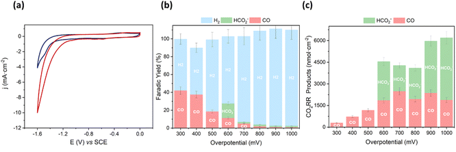
We started the characterization by performing CV of Mn@Terpy-COF|NT under Ar and CO2 atmospheres in K2SO4/K2B4O7 (Fig. 6a). Under Ar (pH 8.2), CV showed an irreversible cathodic wave, suggesting a catalytic hydrogen evolution reaction (HER) that was confirmed by the detection of H2 after control potential electrolysis (see below). When the solution was saturated with CO2 (pH 7.4), the onset of the catalytic wave shifted 360 mV to more positive potentials and the catalytic current increased 3.5-fold (jCO2/jAr at −1.3 V).
To estimate the neat CO2 reduction activity of Mn@Terpy-COF|NT, CPE measurements of the thin film on carbon paper (CP) electrode as a current collector were recorded in aqueous K2SO4/K2B4O7 under CO2 (pH 7.4) (see the Experimental section for details). CPE measurements were carried out to benchmark the CO2 reduction activity selectivity and the stability of the catalyst Mn@Terpy-COF|NT (Fig. 6b and c). The generated products were analyzed by gas chromatography and 1H-NMR. CPE measurements at different applied potentials (from −1.1 to −1.8 V vs. SCE) of Mn@Terpy-COF|NT ([Mn]total = 850 nmol cm−2) showed current densities from −0.06 to −17 mA cm−2. The generated products were quantified (nmol cm−2) at different overpotentials (Fig. 6c), and the selectivity of the CO2 reduction reaction shifted to H2 with the increase of the overpotential. This can be attributed to the protonation of the Mn centers forming the Mn–H species, which further protonates to produce H2, and to the exacerbation of the background reaction of H2 formation by the carbon nanotubes as previously proposed.54 The formation of CO and HCO2− was observed from a low η of 300 mV (Fig. 6b). At η = 600 mV, Mn@Terpy-COF|NT generated 2000 and 2700 nmol cm−2 of CO and HCO2−, respectively. Although the CO obtained was insufficient to be detectable by online GC-MS, CPE experiments with 13CO2 indicated that formate comes from CO2 (Fig. S21†).
Mn@Terpy-COF|NT electrodes showed good stability under catalytic conditions. A superimposition of linear sweep voltammetry (LSV) traces recorded before and after CPE indicates negligible catalyst decomposition (Fig. 7). In general, no significant changes were observed by XPS and SEM analysis before and after electrocatalysis in water under CO2. EDX showed the homogeneous distribution of Mn before and after catalysis, further highlighting the robustness of Mn@Terpy-COF|NT.
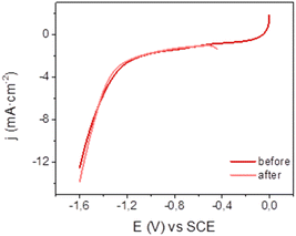 | ||
| Fig. 7 Linear sweep voltammetry of Mn@Terpy-COF|NT ([Mn]total = 850 μmol cm−2) on CP at 10 mV s−1 before and after CPE at −1.3 V vs. SCE in water K2SO4/K2B4O7 under CO2. | ||
To delve into the microscopical morphologies of Mn@Terpy-COF|NT before and after its test as a CO2 reduction catalyst, different SEM-EDX spectra were recorded. Deposition of the Mn@Terpy-COF/NT/Nafion suspension over the electrode resulted in a heterogeneous surface, where Mn@Terpy-COF is embedded in different parts of the carbon-based electrode matrix (Fig. S12†). This microstructure was maintained unchanged after the electrode's testing process, which is promising for a hypothetical long-time use of this dispositive as a CO2 reductive system (Fig. S13†). In addition, XPS spectra of the electrodes after their test as catalysts were recorded, showing no significant change in the C 1s core level with respect to the starting material Mn@Terpy-COF|NT (Fig. S19†). However, the catalyst exhibited altered selectivity in a subsequent catalytic run, producing mainly H2.
Before performing ATR-IR-SEC, we performed CV of Mn@Terpy-COF|NT in dry CH3CN (0.2 M TBAPF6) under Ar. The CV showed several irreversible cathodic waves in the range from −0.1 V to −1.5 V vs. SCE. Besides, during the forward scan, three reoxidation processes were observed at −1.05, −0.5 and 0.6 V vs. SCE, respectively. These redox transformations are similar to those observed for Mn@Terpy molecular complexes previously reported,60 suggesting an electronic similarity for the Mn(κ2-tpy)(CO)3S coordination between Mn@Terpy-COF|NT and Mn@Terpy as ligands.
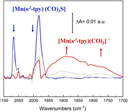
With these considerations, ATR-IR-SEC was carried out to gain structural insights into the electrochemical activation of the Mn@Terpy-COF|NT precatalyst. At open-circuit potential (EOCP), the ATR-FT-IR of Mn@Terpy-COF|NT (Fig. 8) showed a ν(CO) band at 2063 and a broad feature at 1982 cm−1, and the IR pattern corresponds to a fac arrangement within the core structure of the COF, which also matched well with the pattern observed for the complex Mn@Terpy. This profile also agrees with the ν(CO) bands of several reported immobilized facial tricarbonyl manganese polypyridine complexes2 and with that previously observed for COFbpyMn|NT.54 When the potential was stepwise decreased from 0.4 to −1.6 V (vs. SCE), the CO vibrations show an increase in intensities at lower energies with the evolution of the redox potential to more negative values that could be associated with a redox transformation. The ATR-IR-SEC spectra showed a decrease of the precatalyst signals with the concomitant increase of a series of bands at 1937, 1982, 1893, 1827 and 1750 cm−1 indicating the formation of new species. We hypothesized that after the reduction of Mn@Terpy-COF|NT, two different intermediates contributed to the spectra, the dimer and the anionic species (Fig. 8), similar to the intermediates detected for the molecular Mn@Terpy.60
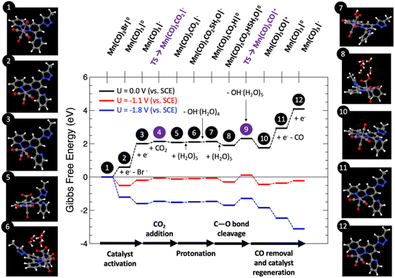
Fig. 9 shows the computed Gibbs free energy diagram for the proposed mechanism, for which all the structures were fully optimized in water solution, for externally applied voltages vs. SCE mimicking the voltage range explored in the experiments: U = 0, −1.1 and −1.8 V.
Catalyst activation. The first step (1) depicts the organometallic unit in the COF system, in which the Mn atom has an oxidation state of +1 and a six-fold coordination with a pseudo-octahedral structure. After two sequential one-electron reductions, two electrons are transferred to the Mn center for the catalyst activation resulting in a net free energy change at U = 0 V of +2.01 eV. The first one-electron reduction leads to barrierless Br− release towards the formation of (2). After that step, (2) can be easily electro-reduced into (3), with a net free energy gain of +1.42 eV. After these two electro-reductions, the two additional electrons are located in the dxy(Mn) orbitals.62
CO2 adsorption and protonation. Once the active species (3) are formed, CO2 can anchor in the Mn vacant site with a computed low energy barrier of 0.26 eV (4), to finally form the Mn–CO2 intermediate (5) with a net free energy change of around +0.07 eV (endergonic) at U = 0 V, and a bond-length Mn–C of around 3.16 Å. After this step, the reaction proceeds by the protonation of the CO2 ligand. This process has been modelled by the explicit inclusion of a (H2O)5 cluster in a chair configuration as previously reported,63 which leads the water cluster to coordinate with CO2 to yield (6). In this step a transfer of a proton is produced from the water cluster to the C–O unit to form (7), followed by the subsequent release of OH−(H2O)4 with a slight net free energy change of +0.03 eV (endergonic) at U = 0 V.
CO release and catalyst regeneration. An explicit (H2O)5 water cluster can coordinate again with (7) to exergonically form (8) (ΔG = −0.23 eV), capturing an OH− by subsequent release of OH−(H2O)5 with a slight net free energy loss of −0.15 eV, leading to the positively charged Mn(CO)3CO|+ unit (10) by surmounting an associated energy barrier of 0.41 eV (9). From this step, the CO release occurs spontaneously by a synergistic electro-reduction with an associated net free energy gain of +1.18 eV at U = 0 V to yield (11). Finally, in order to regenerate the catalyst, (11) can be electro-reduced (ΔG = +1.16 eV) to regenerate active species (3).
Fig. 9 reveals that at U = 0 V vs. SCE, the mechanism is far from being thermodynamically viable, particularly due to the sub-reactions involving the one-electron reductions. Starting from the U = 0 V profile, we have computed the Gibbs free energy paths at U = −1.1 and −1.8 V vs. SCE (see Fig. 9), which correspond to voltage range experimentally explored. Interestingly, at U = −1.1 V the entire reaction becomes exergonic by approximately −0.11 eV. The reaction is limited by step 9, which involves C–O bond cleavage followed by OH− abstraction, with a net energy barrier of 0.71 eV. This result in excellent agreement with the experimental evidence. Finally, at U = −1.8 V the whole reaction is clearly exergonic by <−3 eV. For this case, once again, the C–O bond cleavage and subsequent OH− abstraction is the reaction limiting step, since it is not linked to the externally applied potential, yielding a net barrier of 0.41 eV, 0.3 eV lower than for the U = −1.1 V case, thus justifying the CO production increase. Thus, the atomistic mechanism theoretically proposed clearly predicts the activation of the CO2 reduction/CO evolution channel for the voltage window experimentally explored.
Conclusions
A novel Mn@Terpy-COF has been synthesized from [HC![[triple bond, length as m-dash]](https://www.rsc.org/images/entities/char_e002.gif) C]0.17-TPB-DMTP-COF following a pathway that involves the introduction of a terpyridine fragment into the macromolecular material by a CuAAC reaction, followed by the complexation of the ligand with manganese. This new Mn@Terpy-COF has been shown to be an active catalyst for the electrochemical reduction of CO2 in water. The spectroscopic characterization of Mn@Terpy-COF by IR shows that the Mn center has an a fac coordination environment, homologous to the molecular complex Mn@Terpy and the COFbpyMn. XPS analysis also evidences the formation of Mn@Terpy-COF. Positive shifts in the onset potentials and increases in current are observed in the CV of the frameworks when the atmosphere is changed from Ar to CO2. Mn@Terpy-COF reduces CO2 to CO with a FY of 42% at an overpotential of only 300 mV. In addition, a FY of 16% was observed for formate production at an overpotential of 600 mV.
C]0.17-TPB-DMTP-COF following a pathway that involves the introduction of a terpyridine fragment into the macromolecular material by a CuAAC reaction, followed by the complexation of the ligand with manganese. This new Mn@Terpy-COF has been shown to be an active catalyst for the electrochemical reduction of CO2 in water. The spectroscopic characterization of Mn@Terpy-COF by IR shows that the Mn center has an a fac coordination environment, homologous to the molecular complex Mn@Terpy and the COFbpyMn. XPS analysis also evidences the formation of Mn@Terpy-COF. Positive shifts in the onset potentials and increases in current are observed in the CV of the frameworks when the atmosphere is changed from Ar to CO2. Mn@Terpy-COF reduces CO2 to CO with a FY of 42% at an overpotential of only 300 mV. In addition, a FY of 16% was observed for formate production at an overpotential of 600 mV.
Data availability
The data supporting this article have been included as part of the ESI.†Author contributions
Conceptualization: J. L. S., F. Z., and J. L.-F. investigation: E. G., G. C. D. B., M. V., S. R., M. M. F., and E. S. methodology: E. G., G. C. D. B., S. R., J. I. M., and E. S. writing – original draft: E. G., G. C. D. B., M. M. F., J. I. M., and E. S. writing – review and editing: E. G., M. M. F., E. S., F. Z., J. I. M. E. G. M, J. L.-F., and J. L. S. visualization: all the authors. Project administration and supervision: J. I. M., E. G. M., F. Z., J. L.-F, and J. L. S.Conflicts of interest
There are no conflicts to declare.Acknowledgements
This work was financially supported by Research Project TED2021-129886B-C43, TED 2021-129886B-C42 and TED2021-132790B-I00 granted by MCIN/AEI/10.13039/501100011033 and the European Union NextGeneration EU/PRTR; and Research Project PID2022-138908NB-C33, PID 2022-138908NBC31 and PID2022-140142OB-I00 granted by MCIN/AEI/10.13039/501100011033/ and FEDER A way to make Europe and the Spanish MICINN (PDC 2022-133498-I00). J. L. S. acknowledges the MICIIN for the REDES project “RED2022-134503-T”. J. L.-F. acknowledges Fundación Ramón Areces for the project ElectroFuel and Spanish MCINN for PDC2022-133451-I00. JIM acknowledges financial support from Spanish MCINN (grants PID2020-113142RB-C21, PLEC2021-007906 and TED2021-129416A-I00), Comunidad de Madrid (grant Y2020/NMT-6469), and CSIC (grant BILAT23033). ES and EGM acknowledge financial support from Spanish MICINN (grant PID2021-123295NB-I00). J. L.-F. and G. C. D. B. also acknowledge the financial support of the ICIQ Foundation, the CERCA Program/Generalitat de Catalunya, MCIN through Severo Ochoa Excellence Accreditation 2020–2023 (CEX2019-000925-S, MIC/AEI), AGAUR (2021 SGR 01260), and Excellence in R&D (CEX 2018-000805-M). This work was also supported by the “María de Maeztu” Programme for Units of Excellence in R&D (CEX 2018-000805-M) and the Comunidad de Madrid (MAD2D-CM and TEC-2024/ECO-332) and MICINN (Planes complementarios, Materiales Avanzados). FZ also acknowledges support from the European Innovation Council under grant Agreement 101047081 (EVA).References
- O. S. Bushuyev, P. De Luna, C. T. Dinh, L. Tao, G. Saur, J. van de Lagemaat, S. O. Kelley and E. H. Sargent, Joule, 2018, 2, 825–832 CrossRef CAS
.
- S. Fernandez, G. C. Dubed Bandomo and J. Lloret-Fillol, Manganese Catal. Org. Synth., 2021, 137–181 CrossRef
.
- T. H. Wang, C. Di Dong, J. Y. Lin, C. W. Chen, J. S. Chang, H. Kim, C. P. Huang and C. M. Hung, Sustain, 2021, 13, 1–31 Search PubMed
.
- J. Resasco and A. T. Bell, Trends Chem., 2020, 2, 825–836 CrossRef CAS
.
- N. Jeyachandran, W. Yuan and C. Giordano, Molecules, 2023, 28, 3504 CrossRef CAS PubMed
.
- Z. Li, B. Han, W. Bai, G. Wei, X. Li, J. Qi, D. Liu, Y. Zheng and L. Zhu, Sep. Purif. Technol., 2023, 324, 124528 CrossRef CAS
.
- Z. Zhang, Z. Yang, L. Liu, Y. Wang and S. Kawi, Adv. Energy Mater., 2023, 13, 2301852 CrossRef CAS
.
- C. U. J. Pittman and L. R. Smith, J. Am. Chem. Soc., 1975, 97, 341–344 CrossRef CAS
.
- D. Yang, B. Ni and X. Wang, Adv. Energy Mater., 2020, 10, 2001142 CrossRef CAS
.
- A. Wagner, C. D. Sahm and E. Reisner, Nat. Catal., 2020, 3, 775–786 CrossRef CAS
.
- M. A. W. Lawrence, C. Thompson and S. C. Lorraine, Inorganica Chim. Acta, 2024, 560, 121829 CrossRef CAS
.
- D. C. Grills, M. Z. Ertem, M. McKinnon, K. T. Ngo and J. Rochford, Coord. Chem. Rev., 2018, 374, 173–217 CrossRef CAS
.
- B. Reuillard, K. H. Ly, T. E. Rosser, M. F. Kuehnel, I. Zebger and E. Reisner, J. Am. Chem. Soc., 2017, 139, 14425–14435 CrossRef CAS PubMed
.
- J. J. Walsh, M. Forster, C. L. Smith, G. Neri, R. J. Potter and A. J. Cowan, Phys. Chem. Chem. Phys., 2018, 20, 6811–6816 RSC
.
-
S. Fernández, G. C. Dubed Bandomo and J. Lloret-Fillol, in Recent Highlights II, ed. R. van Eldik, C. D. B. T.-A. in I. C. Hubbard, Academic Press, 2022, pp. 301–353 Search PubMed
.
- S. Sato, K. Saita, K. Sekizawa, S. Maeda and T. Morikawa, ACS Catal., 2018, 8, 4452–4458 CrossRef CAS
.
- X. Zhang, Z. Wu, X. Zhang, L. Li, Y. Li, H. Xu, X. Li, X. Yu, Z. Zhang, Y. Liang and H. Wang, Nat. Commun., 2017, 8, 14675 CrossRef PubMed
.
- E. Torralba-Peñalver, Y. Luo, J.-D. Compain, S. Chardon-Noblat and B. Fabre, ACS Catal., 2015, 5, 6138–6147 CrossRef
.
- C. L. Smith, R. Clowes, R. S. Sprick, A. I. Cooper and A. J. Cowan, Sustain. Energy Fuels, 2019, 3, 2990–2994 RSC
.
-
O. Piermatti, R. Abu-Reziq and L. Vaccaro, in Catalyst Immobilization, 2020, pp. 1–22 Search PubMed
.
- J. J. Walsh, C. L. Smith, G. Neri, G. F. S. Whitehead, C. M. Robertson and A. J. Cowan, Faraday Discuss., 2015, 183, 147–160 RSC
.
- G. Neri, P. M. Donaldson and A. J. Cowan, Phys. Chem. Chem. Phys., 2019, 21, 7389–7397 RSC
.
- H. Fei, M. D. Sampson, Y. Lee, C. P. Kubiak and S. M. Cohen, Inorg. Chem., 2015, 54, 6821–6828 CrossRef CAS
.
- J. J. Walsh, G. Neri, C. L. Smith and A. J. Cowan, Organometallics, 2019, 38, 1224–1229 CrossRef CAS
.
- K. T. Tan, S. Ghosh, Z. Wang, F. Wen, D. Rodríguez-San-Miguel, J. Feng, N. Huang, W. Wang, F. Zamora, X. Feng, A. Thomas and D. Jiang, Nat. Rev. Methods Primers, 2023, 3, 1 CrossRef CAS
.
- Q. Zhang, S. Yan, X. Yan and Y. Lv, Sci. Total Environ., 2023, 902, 165944 CrossRef CAS
.
- Q. J. Wu, J. Liang, Y. B. Huang and R. Cao, Acc. Chem. Res., 2022, 55, 2978–2997 CrossRef CAS
.
- S. Huang, K. Chen and T. T. Li, Coord. Chem. Rev., 2022, 464, 214563 CrossRef CAS
.
- Y. Fan, M. Chen, N. Xu, K. Wang, Q. Gao, J. Liang and Y. Liu, Front. Chem., 2022, 10, 1–8 Search PubMed
.
- Y. Guan, J. Lai and G. Xu, Chemelectrochem, 2021, 8, 2764–2777 CrossRef CAS
.
- C. Li, Y. Ji, Y. Wang, C. Liu, Z. Chen, J. Tang, Y. Hong, X. Li, T. Zheng, Q. Jiang and C. Xia, Nano-Micro Lett., 2023, 15, 113 CrossRef CAS PubMed
.
- J. Wang, Y. Zhang, Y. Ma, J. Yin, Y. Wang and Z. Fan, ACS Mater. Lett., 2022, 4, 2058–2079 CrossRef CAS
.
- S. Abednatanzi, M. Najafi, P. Gohari Derakhshandeh and P. Van Der Voort, Coord. Chem. Rev., 2022, 451, 214259 CrossRef CAS
.
- F. Gao, R. Yan, Y. Shu, Q. Cao and L. Zhang, RSC Adv., 2022, 12, 10114–10125 RSC
.
- H. Y. Cheng and T. Wang, Adv. Synth. Catal., 2021, 363, 144–193 CrossRef CAS
.
-
M. N. Hossain, L. Zhang, R. Neagu and E. Rassachack, Free-Standing Single-Atom Catalyst-Based Electrodes for CO2 Reduction, Springer Nature Singapore, 2024 Search PubMed
.
- I. Barlocco, G. Di Liberto and G. Pacchioni, Energy Adv., 2023, 2, 1022–1029 RSC
.
- C. S. Diercks, Y. Liu, K. E. Cordova and O. M. Yaghi, Nat. Mater., 2018, 17, 301–307 CrossRef CAS
.
- G. Centi and S. Perathoner, Catal. Today, 2009, 148, 191–205 CrossRef CAS
.
- L. Ye, J. Liu, Y. Gao, C. Gong, M. Addicoat, T. Heine, C. Wöll and L. Sun, J. Mater. Chem. A, 2016, 4, 15320–15326 RSC
.
- C. S. Diercks, S. Lin, N. Kornienko, E. A. Kapustin, E. M. Nichols, C. Zhu, Y. Zhao, C. J. Chang and O. M. Yaghi, J. Am. Chem. Soc., 2018, 140, 1116–1122 CrossRef CAS PubMed
.
- H. Liu, J. Chu, Z. Yin, X. Cai, L. Zhuang and H. Deng, Chem, 2018, 4, 1696–1709 CAS
.
- C.-L. Yao, J.-C. Li, W. Gao and Q. Jiang, Chem.–Eur. J., 2018, 24, 11051–11058 CrossRef CAS
.
- N. Huang, K. H. Lee, Y. Yue, X. Xu, S. Irle, Q. Jiang and D. Jiang, Angew. Chem. Int. Ed., 2020, 59, 16587–16593 CrossRef CAS PubMed
.
- M.-D. Zhang, D.-H. Si, J.-D. Yi, S.-S. Zhao, Y.-B. Huang and R. Cao, Small, 2020, 16, 2005254 CrossRef CAS
.
- M. Lu, M. Zhang, C.-G. Liu, J. Liu, L.-J. Shang, M. Wang, J.-N. Chang, S.-L. Li and Y.-Q. Lan, Angew. Chem. Int. Ed., 2021, 60, 4864–4871 CrossRef CAS
.
- B. Han, X. Ding, B. Yu, H. Wu, W. Zhou, W. Liu, C. Wei, B. Chen, D. Qi, H. Wang, K. Wang, Y. Chen, B. Chen and J. Jiang, J. Am. Chem. Soc., 2021, 143, 7104–7113 CrossRef CAS PubMed
.
- H. Dong, M. Lu, Y. Wang, H.-L. Tang, D. Wu, X. Sun and F.-M. Zhang, Appl. Catal., B, 2022, 303, 120897 CrossRef CAS
.
- M. Liu, Y.-R. Wang, H.-M. Ding, M. Lu, G.-K. Gao, L.-Z. Dong, Q. Li, Y. Chen, S.-L. Li and Y.-Q. Lan, Sci. Bull., 2021, 66, 1659–1668 CrossRef CAS PubMed
.
- Y. Bochlin, L. Ezuz, Y. Kadosh, D. Benjamin, Y. Mordekovitz, S. Hayun, E. Korin and A. Bettelheim, ACS Appl. Energy Mater., 2021, 4, 10033–10041 CrossRef CAS
.
- E. M. Johnson, R. Haiges and S. C. Marinescu, ACS Appl. Mater. Interfaces, 2018, 10, 37919–37927 CrossRef CAS PubMed
.
- D. A. Popov, J. M. Luna, N. M. Orchanian, R. Haiges, C. A. Downes and S. C. Marinescu, Dalton Trans., 2018, 47, 17450–17460 RSC
.
- J. Li, D. Zhao, J. Liu, A. Liu and D. Ma, Molecules, 2020, 25, 2425 CrossRef CAS
.
- G. C. Dubed Bandomo, S. S. Mondal, F. Franco, A. Bucci, V. Martin-Diaconescu, M. A. Ortuño, P. H. van Langevelde, A. Shafir, N. López and J. Lloret-Fillol, ACS Catal., 2021, 11, 7210–7222 CrossRef CAS
.
- H. Xu, J. Gao and D. Jiang, Nat. Chem., 2015, 7, 905–912 CrossRef CAS PubMed
.
- Q. Xu, S. Tao, Q. Jiang and D. Jiang, Angew. Chem. Int. Ed., 2020, 59, 4557–4563 CrossRef CAS
.
- X. Li, J. Qiao, S. W. Chee, H.-S. Xu, X. Zhao, H. S. Choi, W. Yu, S. Y. Quek, U. Mirsaidov and K. P. Loh, J. Am. Chem. Soc., 2020, 142, 4932–4943 CrossRef CAS PubMed
.
-
M. J. Frisch, G. W. Trucks, H. B. Schlegel, G. E. Scuseria, M. A. Robb, J. R. Cheeseman, G. Scalmani, V. Barone, G. A. Petersson, H. Nakatsuji, X. Li, M. Caricato, A. V. Marenich, J. Bloino, B. G. Janesko, R. Gomperts, B. Mennucci, H. P. Hratchian, J. V. Ortiz, A. F. Izmaylov, J. L. Sonnenberg, D. Williams-Young, F. Ding, F. Lipparini, F. Egidi, J. Goings, B. Peng, A. Petrone, T. Henderson, D. Ranasinghe, V. G. Zakrzewski, J. Gao, N. Rega, G. Zheng, W. Liang, M. Hada, M. Ehara, K. Toyota, R. Fukuda, J. Hasegawa, M. Ishida, T. Nakajima, Y. Honda, O. Kitao, H. Nakai, T. Vreven, K. Throssell, J. A. Montgomery Jr, J. E. Peralta, F. Ogliaro, M. J. Bearpark, J. J. Heyd, E. N. Brothers, K. N. Kudin, V. N. Staroverov, T. A. Keith, R. Kobayashi, J. Normand, K. Raghavachari, A. P. Rendell, J. C. Burant, S. S. Iyengar, J. Tomasi, M. Cossi, J. M. Millam, M. Klene, C. Adamo, R. Cammi, J. W. Ochterski, R. L. Martin, K. Morokuma, O. Farkas, J. B. Foresman and D. J. Fox, Gaussian 16, Revision C.01, Gaussian, Inc., Wallin, 2016 Search PubMed
.
- P. Giannozzi, S. Baroni, N. Bonini, M. Calandra, R. Car, C. Cavazzoni, D. Ceresoli, G. L. Chiarotti, M. Cococcioni, I. Dabo, A. Dal Corso, S. de Gironcoli, S. Fabris, G. Fratesi, R. Gebauer, U. Gerstmann, C. Gougoussis, A. Kokalj, M. Lazzeri, L. Martin-Samos, N. Marzari, F. Mauri, R. Mazzarello, S. Paolini, A. Pasquarello, L. Paulatto, C. Sbraccia, S. Scandolo, G. Sclauzero, A. P. Seitsonen, A. Smogunov, P. Umari and R. M. Wentzcovitch, J. Phys. Condens. Matter, 2009, 21, 395502 CrossRef PubMed
.
- C. W. MacHan and C. P. Kubiak, Dalton Trans., 2016, 45, 17179–17186 RSC
.
- R. Gostynski, J. Conradie and E. Erasmus, RSC Adv., 2017, 7, 27718–27728 RSC
.
- C. Ci, J. Zang, L. Chao, K. Xiao and X. Peng, Inorganica Chim. Acta, 2023, 549, 121419 CrossRef CAS
.
- C. Riplinger, M. D. Sampson, A. M. Ritzmann, C. P. Kubiak and E. A. Carter, J. Am. Chem. Soc., 2014, 136, 16285–16298 CrossRef CAS
.
Footnotes |
| † Electronic supplementary information (ESI) available. See DOI: https://doi.org/10.1039/d4ta02807d |
| ‡ Elena Gala and Geyla C. Dubed Bandomo contributed equally to this work. |
| This journal is © The Royal Society of Chemistry 2025 |

