
Optimization of gold nanorod arrays for surface enhanced Raman spectroscopy (SERS) detection of atrazine†
Najwan
Albarghouthi
,
Presley
MacMillan
 and
Christa L.
Brosseau
*
and
Christa L.
Brosseau
*
Department of Chemistry, Saint Mary's University, 923 Robie St., Halifax, Nova Scotia, Canada. E-mail: christa.brosseau@smu.ca; Fax: +(902) 496-8104; Tel: +(902) 496-8175
First published on 26th January 2021
Abstract
Recently, there has been increasing concern over the widespread use of the herbicide atrazine which has been reported to have problematic side effects on local ecosystems. This has highlighted the need for rapid and accurate point-of-need assessment tools for analytical determination of herbicides in ground and surface waters. Surface enhanced Raman spectroscopy (SERS) is a sensitive vibrational spectroscopy technique which has recently been employed for the analysis of a variety of analytes in water, ranging from pharmaceuticals to pesticides. In this work, SERS sensors constructed using gold nanorod (AuNR) arrays are optimized and then utilized for the rapid and sensitive detection of atrazine. In this study, the effect of relative humidity on the self-assembly of gold nanorods into arrays was explored, and the SERS performance was assessed using para-aminothiophenol as a SERS probe. Once the SERS performance of the substrates was deemed optimal, the detection of atrazine was highlighted. This work represents the first time that relative humidity has been explored as an optimization strategy for controlled alignment of gold nanorods for SERS analysis of atrazine.
1. Introduction
Atrazine is an herbicide which is used worldwide, and in the US in particular, to control the growth of unwanted plants and improve the yield of many crops, including corn and sugarcane.1,2 Atrazine has been a favoured herbicide for several reasons, including its low cost, ease of application and effectiveness. Starting in the early 2000s, several studies highlighted potential adverse health effects which may be linked to atrazine due to its endocrine disruption properties. For example, atrazine in drinking water has been associated with pre-term delivery in humans, fetal growth restriction and poor semen quality.3 In terms of local ecosystem impacts, atrazine has been reported to impact normal reproductive function in mammals, fish and amphibians.4 In 2004, atrazine was banned by the European Union, however many countries including Mexico, the United States and Australia continue to use atrazine routinely.2 In the US, atrazine is one of the most commonly detected chemicals in drinking water, with the US using 76.4 million pounds of atrazine annually as of 2016.3 Due to the heavy usage and increasing concern regarding the impact of atrazine on ground and surface water quality, there is a great need for analytical instrumentation that can reliably and routinely allow for the determination of atrazine in water samples at the point-of-need.Several analytical techniques are well established for atrazine detection such as HPLC and GC.5 Despite their high sensitivity towards the detection of trace amounts of contaminants these methods typically require both complex sample preparation and a high level of user expertise, which limits their widespread use.5 In addition, HPLC and GC are generally not considered as field-portable, and thus time-sensitive information is lost and in addition, high-throughput capabilities are often lacking.6 Therefore, innovative analytical techniques for the routine and efficient determination of chemicals in ground and surface waters at the point-of-need are needed.
Surface-enhanced Raman spectroscopy (SERS) is a versatile vibrational spectroscopic technique based on the inelastic scattering of light, providing a vibrational fingerprint for molecules adsorbed onto a roughened nanostructured surface typically prepared from a coinage metal (Au, Ag, Cu).7 The enhancement of the incident electromagnetic field is highly dependent on the localized surface plasmon resonance of the metal nanoparticles on the underlying SERS substrate, which in turn is dependent on the size, shape and type of metal nanostructures that are present.7 The recent growth of nanoparticle synthetic strategies has allowed for the production of highly monodisperse particles with extreme control over their size and the shape.8–12 However, a current limitation is the difficulty in assembling these monodisperse particles into scalable, higher order structures such as arrays.13,14 In most cases the particles are randomly distributed on a surface which leads to an inhomogeneous distribution of the SERS signal across the substrate, making quantitative evaluations from SERS signals challenging.15 Many methods have been explored for the fabrication of SERS substrates containing well defined metallic nanostructures with precise separations to generate intense electromagnetic fields over large surface areas; such techniques include self-assembly,16 Langmuir–Blodgett film deposition17 and lithographic methods.18 The ability to trap incident light and efficiently localize it within specific nanoscale configurations in order to produce a significant amplification of the electromagnetic field is found to occur preferentially for sharp particle features such as corners or tips.19 Metal particles, mainly Au and Ag, have been explored for a variety of SERS applications, such as the detection of biological species, toxic chemicals, food additives and pesticides.20–23
SERS-based atrazine detection was reported in several studies by different groups.24–26 For instance; Costa et al. explored the nature of the metal employed as the enhancing substrate which revealed that the detection of atrazine using SERS was not straightforward and requires a better understanding of the interaction/adsorption of the probe molecules at the surface of the substrate.24 The study revealed that Au nanostructured substrates were unable to provide a SERS spectrum specific for atrazine when atrazine was present in a mixture of other triazine derivatives, including simazine. On the other hand, Ag substrates provided a characteristic SERS signal which allowed for ultrasensitive analysis of herbicide mixtures containing similar triazine rings.
Gold is often a preferred metal for SERS substrates due to its strong plasmonic response above 600 nm, excellent biocompatibility, and in particular, the vast amount of synthetic strategies for producing monodisperse gold particles of defined size and shape.27,28 Among the varied gold nanostructures synthesized to date, gold nanorods (AuNRs) have attracted the most interest in the last few decades owing to their unique properties such as their plasmonic tunability, which can be easily adjusted over the UV-vis-NIR wavelength range by simply controlling the nanorod aspect ratio.29 Despite the important plasmonic properties of individual nanostructures, controlling their plasmonic coupling in multiple dimensions and organizing these nanoscale building blocks into more elaborate geometries such as closely spaced nanorod arrays has become an active area of interest and can be exploited in SERS to allow for the ultrasensitive detection of molecules.30–32 Induced evaporation is one of the most efficient and low-cost methods to organise nanostructures into large scale assemblies. By adjusting the evaporation rate, vertically aligned gold nanorod arrays with high uniformity and reproducibility can be produced, with potential use as SERS substrates.33
In addition to the extreme monodispersity which is required to fabricate a novel sensor substrate using this induced evaporation method, other factors can have a significant impact as well as the concentration of the surfactant, temperature, substrate material, humidity, etc.34 The relative humidity (RH) around the drying region plays a significant role in determining the overall nature of the resulting monolayer obtained using induced evaporation.35–37 Zhang et al. demonstrated that the vertical alignment of AuNR arrays on a silicon substrate can be achieved by a simple 2-step method.38 In the first step a droplet of CTAB-capped AuNRs was placed on a flat silicon substrate and incubated with 200 μL of water in a sealed petri-dish for 24 h which leads to shrinkage of the AuNR droplet without formation of a coffee-ring structure. In the second step, water is removed from the petri-dish to allow for complete drying of the AuNR film for 36–48 h at 25 °C. Controlling the evaporation rate of a AuNR droplet provided sufficient time to form a monolayer of standing arrays. Conversely, lateral alignment occurred when the evaporation time was less than 12 h.37–40
The objective of this study was to investigate to what extent the effect of relative humidity plays on the formation of large domains of hexagonally-packed arrays of AuNRs using a simple self-assembly approach, wherein the surface modification of the AuNRs was varied. Once the AuNR arrays were optimized, SERS evaluation was completed using the common SERS probe molecule para-aminothiophenol (p-ATP), after which the optimized SERS substrates were used for the detection of atrazine. It is noteworthy to highlight that substrates prepared at high relative humidity (RH) had more intense and richer vibrational responses than those prepared at low RH. Moreover, the surface coating of the AuNRs is an important factor that led to variation in the resulting spectra.
2. Materials and methods
2.1. Reagents and materials
The following chemicals were purchased from Sigma Aldrich (Oakville, Ontario, Canada) and were used without further purification: hexadecyltrimethylammonium bromide (CTAB, >98.0%), atrazine (C8H14ClN5 ≥ 98.0%, Saint Louis, MO, USA) L-ascorbic acid, hydrochloric acid (HCl, 37 wt% in water), poly (ethylene glycol) methyl ether thiol (average Mn 2000) and para-aminothiophenol (p-ATP, >97%). Silver nitrate (AgNO3, >99.9995%) was purchased from Alfa Aesar (Wardhill, MA, USA). Sodium oleate (NaOL, >97.0%) was purchased from TCI America (Chuo-ku, Tokyo, Japan). Hydrogen tetrachloroaurate trihydrate (HAuCl4·3H2O) was purchased from Strem Chemicals Inc. (Newburyport, MA, USA). Sodium borohydride (NaBH4, 99%), was purchased from Fluka Analytical (Sleeze, Germany). All glassware was cleaned using freshly prepared aqua regia for 30 minutes to dissolve all metal residue followed by rinsing with copious amounts of Milli-Q water (≥18.2 MΩ cm). Silicon wafers were purchased from Ted Pella, Inc. (Redding, CA, USA).2.2. Preparation of AuNRs
Gold nanorods with an aspect ratio of ∼3.4 (length: 73 ± 5 nm, width: 21 ± 2 nm) were synthesized based on a slightly modified method developed by Ye et al. which provided a high NR yield, excellent uniformity and a minimal amount of impurities.41 Briefly, a gold seed solution was prepared by mixing 5 mL of 0.5 mM HAuCl4 with 5 mL of 0.2 M CTAB solution in a vial. Next, 0.6 mL of freshly prepared 0.01 M NaBH4 was diluted to 1 mL with cold water and was injected into the mixture under vigorous stirring for 30 s. The resulting brown seed solution was left undisturbed for 2 hours at room temperature. In a 1 L Erlenmeyer flask, 500 mL of warm (∼50 °C) deionized water was used to dissolve 7.02 g (±0.1 mg) and 1.32 g (±0.1 mg) of CTAB and NaOL, respectively. After the solution was cooled down to 30 °C, 18 mL of 4.0 mM AgNO3 was added and left for 15 min at room temperature. 250 mL of 1 mM of HAuCl4 was added to the solution and stirred for 85 min at 700 rpm after which 1.5 mL of conc. HCl was added and stirred for 15 min at 400 rpm. 1.25 mL of 0.064 M ascorbic acid was then added with vigorous stirring for 30 s before the injection of 0.4 mL of the seed solution which was then left undisturbed overnight. The next day, a total volume of 300 mL of AuNRs was centrifuged twice for 30 minutes at 7000 rpm to remove any excess CTAB. After removing the supernatant in the first round, the AuNR paste was re-dispersed in 0.5 mL of Milli-Q water before the second cycle of centrifugation took place.2.3. AuNR modification with PEG-SH
In order to reduce the spectral interference from CTAB, and to increase the surface capture of analytes in solution, the AuNRs were functionalized with a thiolated polyethylene glycol (PEG-SH). The PEG-SH is able to competitively displace the surface-adsorbed CTAB molecules due to the thiol moiety, which has a strong affinity for the gold surface. In addition, the polyethylene glycol allows partitioning and capture of analyte species into this hydrophilic layer. Modification of the AuNRs with PEG-SH was completed using a slightly modified method from Mahmoud et al.42 3–4 mL of the washed and centrifuged AuNR suspension described above was mixed with 0.4 mL of a 5 mM aqueous solution of PEG-SH (Mn ∼ 2000) under vigorous stirring (1200 rpm) for 2 hours and stirred overnight at 400 rpm. 1.0 mL aliquots of the modified AuNRs were then centrifuged at 6000 rpm for ∼20 minutes (or until the supernatant was clear), after which the supernatant was removed.412.4. Characterization of AuNRs
Ultraviolet–visible (UV-vis) spectroscopic studies were completed in order to measure the extinction spectra for the AuNRs dispersed in water using a Cary 60 spectrophotometer. For scanning electron microscopy (SEM) analysis, the AuNRs were deposited onto silicon wafer substrates and imaged using a TESCAN MIRA 3 LMU Variable Pressure Schottky Field Emission Scanning Electron Microscope, with a maximum resolution of 1.2 nm at 30 kV. Transmission electron microscopy (TEM) was also used for imaging after drop casting 5 μl of the AuNR solution onto Holey Carbon – Cu 200 mesh TEM grids (Electron Microscopy Sciences, Hatfield, PA) using a FEI Tecnai 12 Transmission Electron Microscope (TEM), operating at an acceleration voltage of 220 kV.2.5. Preparation of AuNR Array SERS substrates
10 mL of the CTAB coated AuNRs were dispersed in 2 mL of 2.5 mM CTAB and sonicated for 60 s in a method adapted from Zhang et al. with a slight modification.38,39 10 μl of the gold nanorods were drop cast onto a silicon wafer substrate which was kept in a Petri dish that contained 0.40 mL of water in order to maintain a high relative humidity (99%) which was measured using a mini LCD digital temperature and humidity meter that was placed into the Petri dish as well. The Petri dish was then sealed using parafilm and kept in a closed chamber for 5 days. This procedure under high RH (∼99%) would allow for a vertically-aligned AuNR array formation. To prepare a horizontally-aligned AuNR array, 10 μL of the AuNRs were again added to the silicon substrate, but no water was added to the Petri dish. The RH was maintained between 43–45%, and the dish was sealed with Parafilm and left undisturbed until evaporation was judged to be complete (∼5 days).2.6. SERS measurements
SERS measurements were collected using an Advantage 785 benchtop Raman spectrometer equipped with a 785 nm laser (Intevac Photonics, Santa Clara, USA). The spectrometer resolution is 5 cm−1 and it is equipped with an air-cooled CCD detector. A right-angle optics extension tube was used for all measurements. All SERS spectra were collected at laser powers between 22.3 mW and 59.0 mW for acquisition times of 10 seconds. All spectra are corrected for laser power and acquisition time for ease of comparison, and were baseline corrected as needed using NuSpec software. Ten SERS spectra were collected at various spots on each substrate and the average spectrum is presented in all cases. Data were analyzed using Origin 9.0 software (OriginLab Corporation, Northampton, MA, USA). Image processing was done with the assistance of ImageJ software (NIH, Maryland, USA).3. Results and discussion
3.1. Characterization of AuNRs
Characterization of the AuNRs was completed using UV-vis extinction measurements, as well as scanning electron microscopy (SEM) and transmission electron microscopy (TEM). Fig. 1a provides the UV-vis extinction spectrum. The anisotropic shape of the AuNRs gives rise to two distinct localized surface plasmon resonance (LSPR) modes, a weak transverse mode at ∼510 nm and an intense longitudinal LSPR mode, the position of which varies depending on the length of the rods. Typically, the longitudinal mode for AuNRs is located somewhere between 700–900 nm.43 For the AuNRs produced in this work, the transverse LSPR mode was observed at ∼520 nm and the longitudinal mode was observed at ∼690 nm. In addition, the full width half maximum (FWHM) of the longitudinal mode was calculated to be ∼89 nm, indicating a near-monodisperse preparation. The corresponding TEM image of the AuNRs is shown in Fig. 1b, and the ImageJ software analysis for AuNR length (n = 100) is shown in Fig. 1c. The length of the particles from this analysis was determined to be 73 ± 5 nm, and the width was 21 ± 2 nm, giving an overall aspect ratio of ∼3.4 for the AuNRs.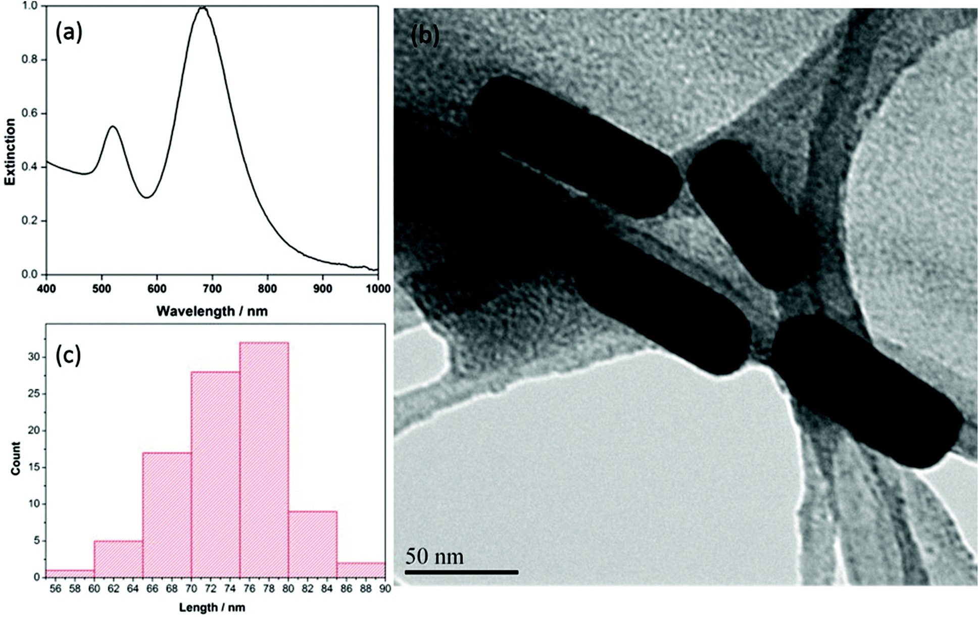 | ||
| Fig. 1 (a) Extinction spectrum of CTAB coated AuNRs in water (b) TEM image of AuNRs at 300kX (c) length distribution of 100 nanorods. | ||
3.2. Assembly of AuNRs using induced evaporation: effects of relative humidity and SERS enhancement
Once a near-monodisperse preparation of the AuNRs was achieved, the next step was to explore induced evaporation of the rods into aligned arrays under different relative humidity conditions. In particular, an exploration of induced evaporation under low (∼45%) and high (∼99%) relative humidity conditions was of interest in this work. This is because the higher relatively humidity environment provides a much slower evaporation rate during which the self-assembly process is taking place, which in turn reduces convection within the droplet, leading to a favourable environment for vertical alignment of the rods.38,39Fig. 2a and b show the SEM images of the AuNR film formed via self-assembly under low RH conditions. In this case, the AuNRs are clearly aligned laterally, planar to the silicon substrate. In addition, the coverage of the film was incomplete, and a significant coffee-ring effect was observed. The majority of the laterally-aligned rods were located at the edges of the droplet, within the coffee-ring structure.38 In an effort to reduce the extent of this coffee-ring effect, the induced evaporation was repeated, but this time under high RH conditions. Fig. 2c and d shows the SEM images of the AuNR film formed under the high RH conditions. In this case, the rods are aligned vertically, perpendicular to the silicon substrate. In addition, no coffee-ring effect was observed for this film, however the coverage of rods over the substrate was irregular, with many well-ordered domains of rods, but also with areas where no rods deposited. In addition, some surface debris was noted on this substrate which was rich in carbon and bromine (as confirmed by EDX spectroscopy), and thus were likely aggregates of CTAB, which is consistent with observations by others.38 | ||
| Fig. 2 (a and b) SEM image of AuNR assembly at low RH at 21.2kX and 202kX, respectively (c and d) SEM image of AuNR assembly at high RH at 22.9kX and 200kX, respectively. | ||
The SERS performance of the AuNR arrays fabricated at low and high RH was investigated through the detection of p-ATP, a common Raman reporter molecule that contains a thiol group which facilitates strong binding to the surface of metal nanoparticles. For both AuNR substrates, 10 μL of a 1.0 mM aqueous solution of p-ATP was drop coated onto the substrate and allowed to air dry. Once dried, the SERS signal was collected. The SERS substrates were not rinsed prior to analysis, as this was deemed unnecessary.
Fig. 3 shows the comparison of the SERS signals for p-ATP collected on both high RH (a) and low RH (b) AuNR array substrates, as well as the background signal (c) for the AuNR substrate prepared at high RH. In all cases, the silicon peak at 521 cm−1 is observed, due to the silicon substrate.14 For both AuNR substrates, SERS spectra of p-ATP show an agreement with the main peaks in the Raman spectrum of the solid powder of p-ATP (Fig. S-1†) with a few shifts in the signature peaks as well as some changes in their corresponding intensities. However, it is worth noting that the substrate prepared under high RH conditions exhibits a more intense SERS signal by a factor of ∼2 as compared to the laterally aligned AuNRs, which is likely due to the increased surface area provided for molecular adsorption, in addition to the strong electromagnetic field enhancement localized at the ends of the vertically-aligned nanorods.44 The signature p-ATP peaks at 392 cm−1, 1080 cm−1 and 1590 cm−1 attributed to (C–S), C(ring)–S and C–C stretching vibrations respectively were observed to be significantly enhanced on a vertically aligned AuNR substrate as compared to the horizontal alignment. Additional peaks at 1004, 1176, and 1489 cm−1 belong to ν(C–C) + δ(C–C), δ(C–H) and [ν(C–C) + ν(C–H)] respectively, and a weak band at 455 cm−1 attributed to (ν(C–N) + ν(C–S) + δ(CCC)) is also observed for the vertically-aligned AuNR arrays. It was reported by Tiwari and coworkers that the ends of the rods are less covered with CTAB and hence, there is enhanced molecular binding at the end of the standing AuNRs.44 While these results for p-ATP were promising and highlighted the potential SERS application for these AuNR arrays, a significant problem observed was the irreproducibility of the SERS signal due to interference with CTAB. CTAB is used in the synthesis of the AuNRs, and in addition, CTAB is added during the induced evaporation process, and as a result the AuNRs are coated with CTAB in what is believed to be a bilayer or interdigitated structure.37 This CTAB layer is difficult to displace, even for thiolated molecules, and hence poses a challenge when trying to use CTAB-coated AuNRs for SERS-based sensing. For the interested reader, the normal Raman spectrum of CTAB powder is provided in Fig. S-2.† As a result, in this work the AuNRs were functionalized with PEG-thiol in an effort to reduce this effect and in turn improve the signal reproducibility of the SERS sensor, as outlined in the next section. These modified AuNRs were then assembled using the same induced evaporation (without CTAB dispersion however) at both low and high relative humidity conditions.
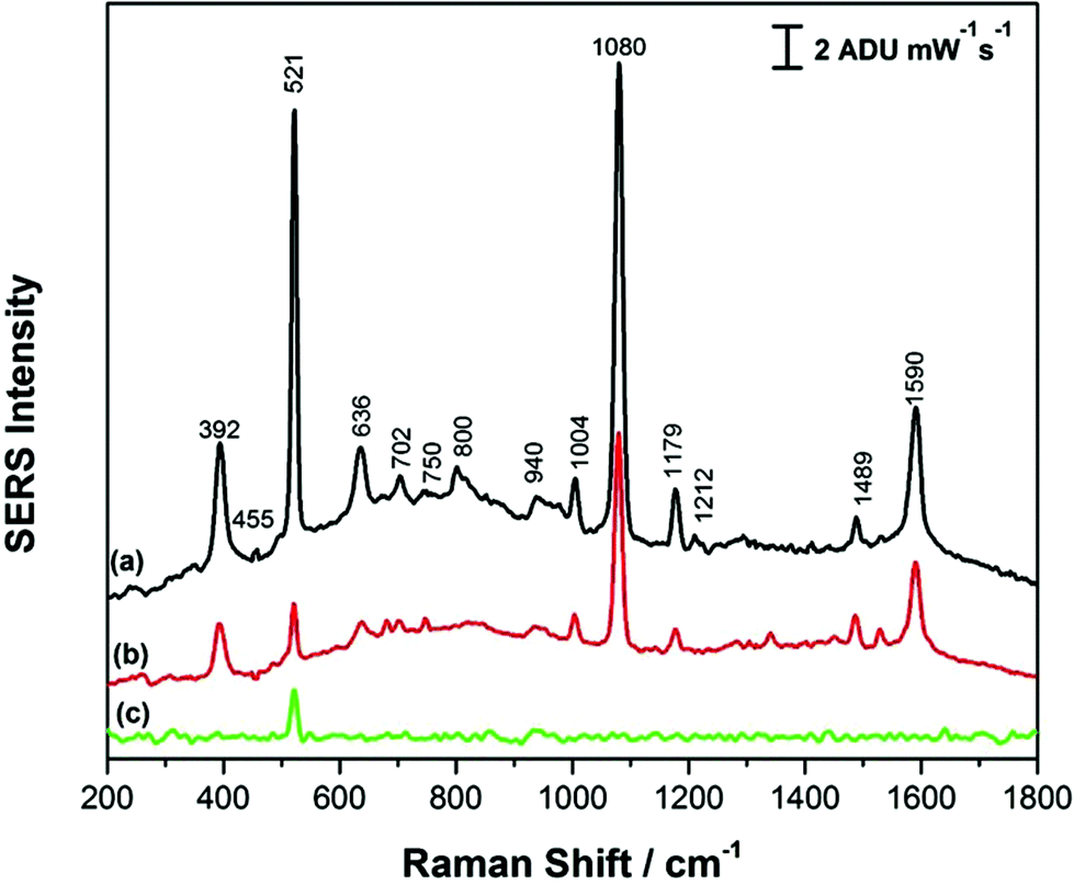 | ||
| Fig. 3 SERS spectrum of (a) 1.0 mM p-ATP on CTAB capped AuNR substrate formed at high RH (b) 1.0 mM p-ATP on CTAB capped AuNR substrate formed at low RH and (c) background signal for CTAB capped AuNR on silicon substrate formed at high RH. | ||
3.3. AuNR modification with PEG-SH: induced evaporation assembly and SERS enhancement
Even though CTAB is a common nanoparticle capping agent that prevents the aggregation of AuNRs, high cytotoxicity limits its widespread application, particularly in the healthcare sector.37 Due to this limitation, many strategies have been explored to replace or eliminate the CTAB on the surface of AuNRs, ranging from thiol modification to polymeric coatings.42,43 One modification in particular which has shown promise is the functionalization of AuNRs with PEG-SH, wherein the CTAB is replaced with a thiolated polyethylene glycol (PEG-SH), ranging in molecular weight from 1 to 10 kDa.42 Functionalization with PEG-SH greatly enhances the stability of the colloidal AuNRs and renders the particles more biocompatible.42 In addition, it has been noted that modification of AuNRs with PEG-SH imparts stability to AuNRs when used for SERS-based sensing, as these modified rods are less sensitive to damage by laser irradiation.45 In this work, modification of the AuNRs with PEG-SH was attempted in order to reduce spectral interference from CTAB, as well as to protect the substrate from laser damage.PEGylation requires an efficient exchange of surfactant from the surface of the AuNRs. This process requires a precise monitoring of many parameters such as pH, temperature, stirring rate, PEG-SH concentration, as well as the speed and time required for centrifugation.45–47 Many protocols have been reported which result in a complete displacement of CTAB with PEG-SH; in general most of these methods require lengthy incubation times (>24 hours) and careful pH control.47 The easiest way to confirm the replacement of CTAB with PEG-SH at the AuNR surface is to monitor the shift of the extinction maxima of the LSPR through UV/Vis spectroscopy where a red shift in the longitudinal mode is indicative of an end-on displacement.47 Fig. S-3a† shows the UV-vis extinction spectrum for the AuNRs after modification with PEG-SH. It can be noted that upon modification with PEG-SH, the λmax for the AuNR longitudinal mode red shifted from 680 nm to 693 nm, indicating an end-on displacement of the CTAB. Fig. S-3b† provides a TEM image of the PEG-SH modified AuNRs. In addition, the FWHM for the extinction spectrum increased from 89 nm to 133 nm which is reflective of an increasingly polydisperse sample.45
Previous work by Zhang et al.38 highlighted many advantages of using AuNRs functionalized with thiolated ligands as opposed to CTAB-coated AuNRs for self-assembly. In particular, thiolated AuNRs provide uniform multilayers of standing arrays which generate very strong electromagnetic fields, useful for SERS.26 However, it was also found that significant repulsion between mPEG-protected AuNRs leads to a horizontal alignment as opposed to large scale standing arrays. Moreover, large-scale fabrication of standing mPEG-protected AuNRs using a one-step evaporation method is difficult and requires several centrifugation steps that may lead to loss of gold nanorods.
In the present work, the AuNRs modified with PEG-SH as described above were allowed to self-assemble on the silicon wafer substrate using the induced evaporation method outlined previously. The self-assembly process was again allowed to occur under conditions of low RH (45%) and high RH (99%). Fig. 4a and b show the SEM images of the PEGylated AuNR film formed at low relative humidity at low and high magnification, respectively. It can be noted that the PEGylated rods are densely packed in a lateral alignment, with the AuNRs covering a large amount of the underlying substrate. In addition, no coffee-ring effect was observed for this film. Fig. 4c and d show the SEM images of the PEGylated AuNR film formed at high relative humidity at low and high magnification, respectively, where the nanorods are now densely packed into a vertically aligned structure, again exhibiting good coverage (including multiple layers) of the substrate with no coffee-ring effect observed. Clearly, the relative humidity of the surrounding environment during evaporation plays a large role in the final alignment of the PEGylated AuNRs.38,39
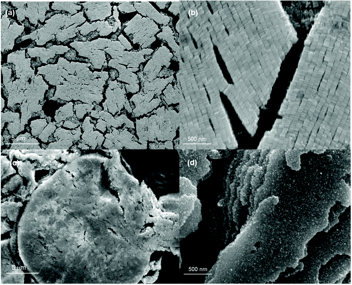 | ||
| Fig. 4 (a and b) SEM image of AuNR assembly at low RH after PEG-SH modification at 16.6kX and 113kX respectively (c and d) SEM image of AuNR assembly at high RH at 19.7kX and 144kX respectively. | ||
Fig. 5 shows the SERS signals for p-ATP collected for the PEGylated AuNR films formed under conditions of high (Fig. 5a) and low (Fig. 5b) relative humidity. Fig. 5c shows the SERS signal in the absence of p-ATP for the PEGylated SERS substrate, as a reference. Comparing the SERS signals for the PEGylated substrates to the CTAB-coated AuNR substrates (Fig. 3), it can be noted that the p-ATP signal intensity has increased by a factor of ∼2. Also, the AuNR coverage of the silicon substrate noticeably increased, not only in the SEM images, but this is also reflected in the decreased intensity of the 520 cm−1 band due to silicon, an indication that less signal is being collected from the underlying silicon wafer. Again, as was observed previously for the CTAB-coated AuNRs, the SERS substrate obtained under high relative humidity conditions had a more intense SERS signal for the p-ATP, by a factor of approximately 5 in this case. Moreover, collecting SERS signal on the PEGylated AuNR substrate was relatively straightforward, with good signal reproducibility observed over the entirety of the surface.
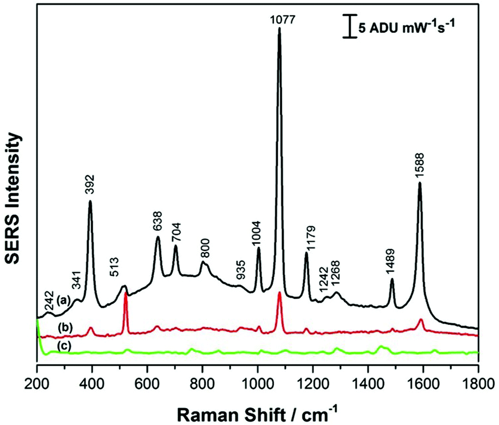 | ||
| Fig. 5 SERS spectrum of (a) 1.0 mM p-ATP on AuNRs after PEG-SH modification at high RH (b) 1.0 mM p-ATP AuNRs after PEG-SH modification at low RH and (c) AuNRs after PEG-SH modification on silicon substrate at high RH. | ||
For further assessment, the coefficient of variance (CV) was used for the evaluation of the SERS substrates prepared in this work. In this case, the intensity of the ∼1080 cm−1 peak for p-ATP was calculated for 10 randomly selected spots on each SERS array substrate (PEGylated AuNR and CTAB AuNR). The average intensity and the standard deviation were then calculated for each to give the coefficient of variance (CV), also known as the % relative standard deviation.
For SERS substrates, CV values of less than 20% are considered ideal, with values above this resulting in too much signal variability for accurate quantitative analyses. In this work, the CV for the CTAB coated AuNR arrays was 49% (low RH) and 18% (high RH), while for the PEGylated AuNR arrays the CV values were 36% (low RH) and 6% (high RH). The raw data for these four cases is provided in Fig. S-4.† These results suggest that for both AuNR arrays, the films formed under high RH conditions demonstrate better analytical performance, and between the CTAB and PEGylated AuNR substrates, the PEGylated AuNR array formed under high RH condition has an excellent CV and should therefore be useful for the detection of atrazine.
To further probe the analytical performance of the AuNR array, quantitative analysis for p-ATP detection was completed, and the results are shown in Fig. 6. In this case, the SERS data was collected for concentrations of p-ATP ranging from 0.01 mM to 10 mM, and the data was averaged, and is plotted in Fig. 6a. Fig. 6b and c plot the average intensity (peak height) as a function of the log of the concentration for the 1174 and 1576 cm−1 peaks, respectively. It is clear that the signal intensity is linear with log concentration over at least 4 orders of magnitude, suggesting that the AuNR array has a good linear dynamic range. From the calibration data, the limit of detection was estimated to be 1.8 μM, based on the standard deviation determination for the blank.
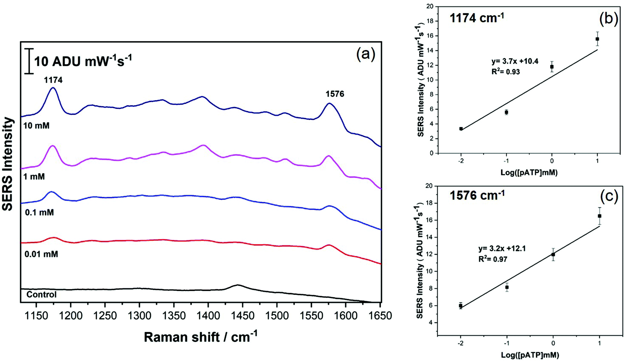 | ||
| Fig. 6 (a) SERS spectra for p-ATP recorded at 4 different concentrations (0.01 mM to 10 mM). (b) and (c) Plot the calibration data for the p-ATP study using the peak intensity (peak height) for the 1174 and 1576 cm−1 peaks, respectively. | ||
3.4. Atrazine detection
Atrazine, as noted above, is a widely applied herbicide which can have harmful ecosystem impacts. As such, the goal of this study was to detect atrazine in aqueous samples using SERS, with the idea being that the AuNR array substrates would provide an efficient and reproducible enhancement of the Raman signal. As noted in the introduction, SERS studies of atrazine have shown promise, however the signals observed for Au substrates indicate a poor selectivity among triazine-containing molecules. In addition, while a few papers have reported on SERS-based quantitation of atrazine using Au substrates,25 there remains work to be done to extend the linear dynamic range for quantitation as well as to lower the limit of detection and improve the selectivity for atrazine sensing.Unlike p-ATP, which is a small aromatic thiol, atrazine is a more challenging molecule to detect using SERS. As a result, components of the AuNR synthesis may pose a spectral interference, in particular CTAB and PEG-SH. Therefore, the normal Raman spectra for the pure powder of both of these substances was recorded for reference prior to the initiation of the atrazine studies, as shown in Fig. S-2 and S-5.† In addition, the normal Raman spectrum of atrazine powder was collected for reference and is shown in Fig. S-6.†
CTAB and PEG-SH-coated AuNR array substrates at both high and low RH were investigated for the detection of atrazine in this work. For all investigations, 5.0 μL of a 1.0 mM aqueous solution of atrazine was drop-cast onto the SERS substrate and allowed to air-dry for ∼30 minutes prior to analysis. All results were compared with theoretical and experimental work previously reported by Costa et al., Rubira and Bonora, as well as the normal Raman spectra presented in the ESI† of this work.24–26 For CTAB-capped AuNR array substrates prepared under conditions of low RH, the SERS response for atrazine was not obvious, as highlighted in Fig. 7a, while the signal of atrazine obtained from CTAB-capped AuNR arrays prepared at high RH displayed a much more intense SERS signal as shown in Fig. 7b. However, further analysis of the SERS spectrum recorded in Fig. 7b revealed that CTAB has a significant contribution to the signal and the spectrum is therefore a mixture of both CTAB and atrazine; for example peaks at 1445, 1390, 1296, 915, 760, and 445 cm−1 can all be attributed to CTAB and not atrazine. This spectral interference of CTAB when using CTAB-capped AuNRs for the SERS detection of a weakly adsorbing analyte such as atrazine is clearly problematic.
 | ||
| Fig. 7 SERS spectrum of 1.0 mM atrazine on CTAB-capped AuNR array at (a) low RH and (b) high RH. SERS spectrum of the CTAB-capped AuNR array in the absence of atrazine is provided for comparison in red for each case. | ||
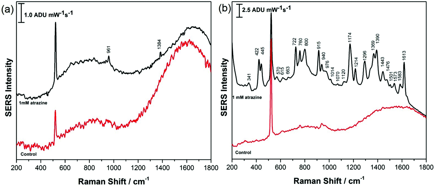
AuNR array substrates fabricated using PEG-modified AuNRs showed significant promise as shown in Fig. 8, for substrates prepared at both low and high RH. In this case, for both the low RH lateral configuration of the rods and the high RH vertical alignment of the rods, the SERS signal for atrazine was strong and there was relatively little spectral interference from the PEG coating on the rods as noted in the control spectra. Both spectra presented in Fig. 8 are in excellent agreement with spectra of atrazine reported by others as well as the normal Raman spectra provided in Fig. S-6.† It appears that a nanorod array configured vertically (Fig. 8b) provides a stronger SERS signal for atrazine, possibly a consequence of the greater abundance of end-on facets of the rods, where less interference from PEG adsorption is expected. Of particular note is the intensity of the characteristic mode at 961 cm−1 for atrazine, due to a ring breathing mode of the triazine ring. Clearly in both cases, atrazine is directly detected using SERS from a dilute aqueous solution of atrazine, and this is greatly assisted by both the modification and alignment of the AuNRs that compose the SERS nanorod array. This is of particular importance as recent studies have highlighted how challenging direct SERS detection of atrazine is, due to a weak affinity for the metal surface and a concentration-dependant adsorption orientation.48
 | ||
| Fig. 8 SERS spectrum of 1.0 mM atrazine on PEG-SH modified AuNR array formed at (a) low RH and (b) high RH. SERS spectrum of the PEG-SH modified AuNR array in the absence of atrazine is provided for control in both cases. | ||
Despite some success in the detection of atrazine, this work also highlights some challenges. For example, detection of atrazine could be detected down to 0.1 mM, but not below this concentration (Fig. S-7†), suggesting that further innovation is needed for the AuNR array platform in order to bring the sensitivity for atrazine to where it would need to be to be practically useful for point-of-need sensing (i.e. ∼0.01 μM). In the future, we plan to explore EC-SERS using these AuNR array substrates, which will likely boost the sensitivity by several orders of magnitude. In addition, quantitative analysis of atrazine is challenging at present, since the molecule displays a concentration-dependant SERS signal, which makes robust quantitative studies problematic. To explore this behaviour further, we are currently conducting EC-SERS studies of atrazine on silver, which clearly shows an orientationally-dependent SERS signal, suggesting that EC-SERS using the AuNR arrays highlighted in this work may offer more promise for the quantitative analysis of low levels of atrazine.
4. Conclusions
This work sought to explore the controlled self-assembly of functionalized AuNRs into horizontally and vertically aligned nanorod arrays, with the goal of developing sensitive and selective substrates for SERS detection of a common environmental contaminant, the herbicide atrazine. It was shown that by controlling the relative humidity during drying, drop-cast films of AuNRs deposited onto silicon wafers can be organized into high-coverage nanorod arrays. In particular, it was noted in this study that CTAB poses an interference not only for efficient nanorod assembly, but also for adequate SERS detection of weakly adsorbing analytes such as atrazine. This work highlighted the importance of replacement of CTAB with PEG-SH for the design of functional SERS substrates based on gold nanorods which form the basis of a SERS substrate for rapid and quantitative SERS detection of environmental contaminants at the point-of-need. Future work will focus on improving the analytical performance of the sensor for potential point-of-need applications.Conflicts of interest
There are no conflicts of interest to declare.Acknowledgements
The authors would like to recognize Dr Xiang Yang for his assistance with SEM and Dr Ping Li for his assistance with TEM. Christa L. Brosseau acknowledges the Natural Sciences and Engineering Research Council (NSERC), Canada Foundation for Innovation (CFI), Research NS and the Canada Research Chairs program for support for this work.References
- N. Belkhamssa, C. I. L. Justino, P. S. M. Santos, S. Cardoso, I. Lopes, A. C. Duarte, T. Rocha-Santos and M. Ksibi, Talanta, 2016, 146, 430–434 CrossRef CAS.
- C. MacLoughlin, I. S. Canosa, G. R. Silveyra, L. S. L. Greco and E. M. Rodríguez, Ecotoxicol. Environ. Saf., 2016, 131, 96–103 CrossRef CAS.
- L. T. Stayner, K. Almberg, R. Jones, J. Graber, M. Pedersen and M. Turyk, Environ. Res., 2017, 152, 294–303 CrossRef CAS.
- A. Nawaz, A. Razpotnik, P. Rouimi, G. de Sousa, J. P. Cravedi and R. Rahmani, Cell Biol. Toxicol., 2014, 30(1), 17–29 CrossRef CAS.
- X. Liu, Y. Yang, L. Mao, Z. Li, C. Zhou, X. Liu, S. Zheng and Y. Hu, Sens. Actuators, B, 2015, 218, 1–7 CrossRef CAS.
- H. Wei, S. M. H. Abtahi and P. J. Vikesland, Environ. Sci.: Nano, 2015, 2(2), 120–135 RSC.
- C. L. Haynes, A. D. McFarland and R. P. Van Duyne, Anal. Chem., 2005, 77(17), 338–346 CrossRef.
- B. Nikoobakht and M. A. El-Sayed, Chem. Mater., 2003, 15(10), 1957–1962 CrossRef CAS.
- G. González-Rubio, V. Kumar, P. Llombart, P. Díaz-Núñez, E. Bladt, T. Altantzis and A. Guerrero-Martínez, ACS Nano, 2019, 13(4), 4424–4435 CrossRef.
- M. Rycenga, C. M. Cobley, J. Zeng, W. Li, C. H. Moran, Q. Zhang and Y. Xia, Chem. Rev., 2011, 111(6), 3669–3712 CrossRef CAS.
- O. Stamatoiu, J. Mirzaei, X. Feng and T. Hegmann, Liq. Cryst., 2011, 331–393 Search PubMed.
- C. Lee, C. S. Robertson, A. H. Nguyen, M. Kahraman and S. Wachsmann-Hogiu, Sci. Rep., 2015, 5, 11644 CrossRef CAS.
- N. Vogel, M. Retsch, C. A. Fustin, A. del Campo and U. Jonas, Chem. Rev., 2015, 115(13), 6265–6311 CrossRef CAS.
- M. Ranjan and S. Facsko, Nanotechnology, 2012, 23, 485307 CrossRef.
- L. Zhao, J. Blackburn and C. L. Brosseau, Anal. Chem., 2014, 87(1), 441–447 CrossRef.
- M. Brust, D. Bethell, C. J. Kiely and D. J. Schiffrin, Langmuir, 1998, 14(19), 5425–5429 CrossRef CAS.
- N. L. Netzer, Z. Tanaka, B. Chen and C. Jiang, J. Phys. Chem., 2013, 117(31), 16187–16194 CAS.
- K. M. Kosuda, J. M. Bingham, K. L. Wustholz and R. P. Van Duyne, Handb. Nanoscale Opt. Electron., 2010, 309, 309–346 Search PubMed.
- B. Sharma, R. R. Frontiera, A. I. Henry, E. Ringe and R. P. Van Duyne, Mater. Today, 2012, 15(1–2), 16–25 CrossRef CAS.
- X. Zhang, N. C. Shah and R. P. Van Duyne, Vib. Spectrosc., 2006, 42(1), 2–8 CrossRef CAS.
- J. Y. Xu, J. Wang, L. T. Kong, G. C. Zheng, Z. Guo and J. H. Liu, J. Raman Spectrosc., 2011, 42, 1728–1735 CrossRef CAS.
- Y. Cheng, Y. Dong, J. Wu, X. Yang, H. Bai, H. Zheng and M. Li, J. Food Compos. Anal., 2010, 23(2), 199–202 CrossRef CAS.
- F. K. Alsammarraie and M. Lin, J. Agric. Food Chem., 2017, 65(3), 666–674 CrossRef CAS.
- J. C. Costa, R. A. Ando, P. H. Camargo and P. Corio, J. Phys. Chem. C, 2011, 115, 4184–4190 CrossRef CAS.
- S. Bonora, E. Benassi, A. Maris, V. Tugnoli, S. Ottani and M. Di Foggia, J. Mol. Struct., 2013, 1040, 139–148 CrossRef CAS.
- R. J. Rubira, S. A. Camacho, P. H. Aoki, M. D. Maximino, P. Alessio, C. S. Martin and C. J. Constantino, Colloid Polym. Sci., 2014, 292(11), 2811–2820 CrossRef CAS.
- X. Huang, S. Neretina and M. A. El-Sayed, Adv. Mater., 2009, 21(48), 4880–4910 CrossRef CAS.
- Y. C. Yeh, B. Creran and V. M. Rotello, Nanoscale, 2012, 4(6), 1871–1880 RSC.
- L. An, Y. Wang, Q. Tian and S. Yang, Materials, 2017, 10(12), 1372 CrossRef.
- A. Apte, P. Bhaskar, R. Das, S. Chaturvedi, P. Poddar and S. Kulkarni, Nano Res., 2015, 8(3), 907–919 CrossRef CAS.
- A. Sánchez-Iglesias, M. Grzelczak, G. Pérez-Juste and L. M. Liz-Marzán, Angew. Chem., Int. Ed., 2010, 49, 9985–9989 CrossRef.
- M. Grzelczak, J. Vermant, E. M. Furst and L. M. Liz-Marzán, ACS Nano, 2010, 4(7), 3591–3605 CrossRef CAS.
- B. Peng, G. Li, D. Li, S. Dodson, Q. Zhang, J. Zhang and Q. Xiong, ACS Nano, 2013, 7(7), 5993–6000 CrossRef CAS.
- X. C. Jiang and M. P. Pileni, Colloids Surf., A, 2007, 295(1–3), 228–232 CrossRef CAS.
- T. Ming, X. Kou, H. Chen, T. Wang, H. L. Tam, K. W. Cheah, J. Y. Chen and J. Wang, Angew. Chem., Int. Ed., 2008, 120(50), 9685–9690 CrossRef.
- R. A. Alvarez-Puebla, A. Agarwal, P. Manna, B. P. Khanal, P. Aldeanueva-Potel, E. Carbó-Argibay and L. M. Liz-Marzán, Proc. Natl. Acad. Sci. U. S. A., 2011, 108(20), 8157–8161 CrossRef CAS.
- T. Xu, X. Wang, Y. Huang, K. Lai and Y. Fan, Food Control, 2019, 106, 106720 CrossRef CAS.
- Z. Zhang and M. Lin, J. Mater. Chem. C, 2014, 2(23), 4545–4551 RSC.
- Z. Zhang, Q. Yu, H. Li, A. Mustapha and M. Lin, J. Food Sci., 2015, 80(2), N450–N458 CrossRef CAS.
- J. Dong, X. Zhao, W. Gao, Q. Han, J. Qi, Y. Wang and M. Sun, Nanoscale Res. Lett., 2019, 14(1), 118 CrossRef.
- X. Ye, C. Zheng, J. Chen, Y. Gao and C. B. Murray, Nano Lett., 2013, 13(2), 765–771 CrossRef CAS.
- M. A. Mahmoud, Phys. Chem. Chem. Phys., 2014, 16(47), 26153–26162 RSC.
- L. Su, S. Hu, L. Zhang, Z. Wang, W. Gao, J. Yuan and M. Liu, Small, 2017, 13(11), 1602896 CrossRef.
- N. R. Tiwari, M. Y. Liu, S. Kulkacoorni and Y. Fang, Nanophotonics, 2011, 5(1), 053513 CrossRef.
- X. Du, W. C. Lin, Q. Shou, X. Liang and H. Liu, Colloid Polym. Sci., 2019, 297(6), 891–902 CrossRef CAS.
- Y. Wang and C. Dellago, J. Phys. Chem. B, 2003, 107(35), 9214–9219 CrossRef CAS.
- C. Kinnear, H. Dietsch, M. J. Clift, C. Endes, B. Rothen-Rutishauser and A. Petri-Fink, Angew. Chem., Int. Ed., 2013, 52(7), 1934–1938 CrossRef CAS.
- R. J. L. Rubira, C. J. L. Constantino, J. C. Otero and S. Sanchez-Cortes, J. Raman Spectrosc., 2020, 51(2), 264–273 CrossRef CAS.
Footnote |
| † Electronic supplementary information (ESI) available. See DOI: 10.1039/d0an02215b |
| This journal is © The Royal Society of Chemistry 2021 |