
Probing the magnetic domain interaction and magnetocapacitance in PVDF – (nickel–cobalt–manganese ferrite)@barium titanate core–shell flexible nanocomposites
K. S.
Deepa
*a,
S.
Premkumar
 bc,
Bishakha
Ray
d,
Suwarna
Datar
d,
V. L.
Mathe
*c and
Sunit B.
Rane
*a
bc,
Bishakha
Ray
d,
Suwarna
Datar
d,
V. L.
Mathe
*c and
Sunit B.
Rane
*a
aAdditive Manufacturing & Advanced Materials-Electronics & Energy (AM2E2), Centre for Materials for Electronics Technology, Pashan, Pune 411008, India. E-mail: sunit@cmet.gov.in; deepa_deeps82@yahoo.co.in
bArmament Research and Development Establishment, Pune, 411021, India
cDepartment of Physics, Savitribai Phule Pune University, Pune 411007, India. E-mail: vlmathe2020@gmail.com
dDefence Institute of Advanced Technology (DIAT), Pune, 411025, India
First published on 4th September 2024
Abstract
In this paper, we report a facile method to synthesize Ni0.93Co0.02Mn0.05Fe1.95O4−δ (NCMF)@BaTiO3 (BT) core–shell nanoparticles. Flexible thick films of polyvinylidene fluoride (PVDF)-NCMF@BT core–shell nanocomposites with a thickness ∼110 μm were developed. We analysed the impact of the BT shell phase on the magnetic domain distribution and its interaction on the final properties of the composites. The magnetic force microscopy (MFM) microstructure revealed well confined, highly dense, and isolated nanodomains of NCMF. The adequate isolation provided by the BT encapsulation highly reduced the potential of charge leakage among the neighbouring NCMF nanoparticles, and hence, the dielectric loss. Their magnetodielectric measurements demonstrated good sensing performance even at a modest magnetic field of 100 Oe. At 1 kHz, significant magnetocapacitance (MC) and magnetoresistance (MR) values of 1.7% and −4.2% were achieved at 100 Oe and these values increased to a maximum of 4.9% and −10.8% at 1000 Oe for PVDF-50 vol% of the NCMF@BT nanopowder composite, respectively, making them a promising candidate for advanced magnetically ordered pseudocapacitive materials in energy storage in supercapacitor applications.
Introduction
In the realm of advanced materials and multifunctional composites, three-phase magnetoelectric polymer composites represent a captivating and dynamic area of research and innovation. These materials are at the forefront of scientific exploration, offering a unique blend of electrical, magnetic, and mechanical properties that make them exceptionally promising for making multifunctional miniaturised devices with attributes like low cost, flexibility, transparency and biocompatibility, which has led researchers to the field of polymer-based composite materials.1–3 Interfaces within these nanocomposites play a pivotal role, as they have the potential to either enhance or constrain the overall material's performance. This is primarily due to the substantial contrast between the surface area and volume of the reinforcing phase and its aspect ratio.4,5 Consequently, the expansive surface areas of nanofillers, coupled with the molecular interactions between the polymer and nanoparticles, offer the prospect of introducing distinct properties or functionalities not present in the pristine polymer.6 Examples of these include the nucleation of a ferroelectric phase of PVDF, which along with the magnetic phase, gives rise to enhanced dielectric, magnetic and magnetoelectric (ME) properties of the composites with respect to the pristine polymers.7,8Flexible composite structures are found to be important from the perspective of applications in biomedical applications, information technology, data storage, sensors, actuators, magnetic resonance imaging, catalysis, telecommunication, environmental remediation, etc.,9–11 as well as fundamental understanding.12 In a broad sense, composites can be fabricated using different approaches, such as core–shell inorganic structure, self-assembled structures, organic–inorganic structures, etc.13–16 Among these materials, composites having coupled magnetic as well as dielectric properties offer an additional degree of freedom because the applications based on both magneticpolymer and ferroelectric/dielectric polymer composites can be explored from a single material matrix. As these are multiphase composites, on the one hand, the characteristics properties of the individual phases are suppressed; and on the other hand, multiple distinct properties are evolved. The ME coupling in this type of composites may result from a linear elastic interaction between the ferrimagnetic particles or their agglomerates and the polar microdomains of the semi-crystalline polymer.
In recent studies, there has been a greater emphasis on studying the changes in the microstructure of magnetic domains when subjected to either an electric or magnetic field.17 The microstructural domain evolution plays a crucial role in various applications, such as multiferroic data storage systems, nanoscale devices and sensors, where ME coupling at the nanoscale is utilized rather than the microscopic interaction.18 Among different characterisation techniques, MFM is a simple and adaptable technique that may be used in numerous environmental conditions without the need for any specific sample preparation. Using MFM, Zavaliche et al. demonstrated an electric field induced room temperature magnetization reversal in epitaxial BiFeO3–CoFe2O4 columnar nanostructures.19 Moreover, G. Caruntu et al. measured the ME coefficient in bilayered ceramic nanocomposites by observing the variation in the longitudinal piezoelectric coefficient of the electrostrictive layer.20 Bishaka Ray et al. studied the variation in the magnetic domain structure using MFM, in graphene nanoribbon (GNR) conjugated Fe3O4 and Ni nanoparticles. They observed that the magnetic properties and the imaged magnetic domain structures are influenced by the concentration of the ferromagnetic material conjugated with GNR. Hence, to gain a thorough understanding of the magnetic domain interaction and resulting magnetic properties in the core–shell structure of NCMF@BT, MFM is employed as a fundamental characterization technique.
Poly(vinylidene fluoride) (PVDF) is chosen as the matrix phase, as it is well known for its ferro-, pyro- and piezoelectric properties. PVDF is also known for its different polymorphic nature. However, the β and γ phases of PVDF alone show the piezoelectric behaviour.21 Beyond this, PVDF is renowned for its excellent halogen and acid resistance, good biocompatibility, and environmental friendliness.22 Arti et al.23 demonstrated a three-phase BT-CoFe2O4-PVDF composite with a notable magnetoelectric response of 26 mV cm−1 Oe, enabled by low-temperature processing and effective CFO-BT interaction. Using a similar system containing 10 wt% CFO-10 wt% BT-PVDF, A. Mooti et al.3 studied the dielectric and magnetic properties, and obtained a dielectric constant of 26 at 1 KHz and a magnetisation of 5.7 emu g−1. Nevertheless, the primary challenge encountered in such ferrite-based polymer composites is the formation of a charge leakage channel caused by the interconnected grains of ferrite nanoparticles that extend throughout the polymer matrix. Instead of utilising ferrite and BT as distinct phases, a core–shell nanoparticle structure can be employed, with ferrite as the core and BT as the shell. In this configuration, the outer BT shell layer serves a dual purpose: it acts as both the ferroelectric phase and an insulating layer, preventing direct contact between the nearest neighbouring ferrite nanoparticles. The incorporation of core–shell ME nanoparticles in a polymer composite results in the alteration of the magnetic domain structure and its corresponding characteristics. To efficiently utilise these composites, it is imperative to analyse the impact of the microstructure on the properties of the composites. The present study focuses on conducting a thorough examination of the magnetic domain structure and the magnetic, structural, microstructural and magnetocapacitance properties of a flexible structure that contains core–shell ME composites dispersed in a PVDF matrix.
In this article, we outline a straightforward, two-step, and scalable production process for core–shell nanoparticles. A flexible and self-standing multiferroic inorganic–organic hybrid film was subsequently produced using PVDF with PVDF@BaTiO3 core–shell nanoparticles. The piezomagnetic phase chosen for the present study is NCMF, as it shows good ferrimagnetic properties, along with high resistivity.24,25 Owing to its simplest composition with excellent dielectric and piezoelectric properties, lead-free BaTiO3 was chosen as the ferroelectric phase.26
Materials and methods
Synthesis of the NCMF nanopowder
NCMF nanoparticles were produced using the hydrothermal method. The required quantities of FeCl3 (99%, Aldrich Chemicals), Ni(NO3)2·6H2O (99%, Aldrich Chemicals), Co(NO3)2·6H2O (99.5%, Aldrich Chemicals), and MnCl2·4H2O (98%, Merck Chemicals) were determined based on the composition Ni0.93Co0.02Mn0.05Fe1.95O4−δ (NCMF). The calculated amounts of salts were weighed and dissolved in deionized water until it became a uniform solution. To prevent agglomeration during autoclaving, 1 wt% polyethylene glycol (PEG)-6000 (99%, Aldrich Chemicals), which acts as a good surfactant, was added to the above solution. A separate 8 M NaOH solution was prepared and kept at a temperature of 80 °C using a water bath. The homogeneous precursor solution containing all the metal ions was added dropwise to an aqueous solution of NaOH while vigorously stirring, resulting in the formation of a homogeneous brown precipitate. The stirring persisted for an additional 30 minutes, and the mixture was then rapidly cooled to ambient temperature using a water bath. The brown suspension was then transferred to an autoclave and subjected to heating at a temperature of 180 °C for a duration of 24 hours. Once the powder had cooled to room temperature on its own, it was repeatedly rinsed with distilled water until it reached a neutral pH. Finally, it was washed with ethanol. The obtained NCMF nanopowder was subsequently subjected to 12 hour vacuum drying at a temperature of 80 °C.Synthesis of the NCMF@BaTiO3(BT) core–shell nano composite
The core–shell nanostructure of NCMF@BT with a 1![[thin space (1/6-em)]](https://www.rsc.org/images/entities/char_2009.gif) :1 molar ratio was synthesised by simple sol–gel technique. To synthesise the BT nanoparticles, 0.01 mole of barium acetate was dissolved in acetic acid. After complete dissolution, 0.01 mole of titanium tetra isopropoxide was added to the same solution under constant magnetic stirring. The precursor solution was heated at 100 °C for 30 minutes to form a thick gel. The gel was further dried in an oven at 150 °C for 12 hours, ground to a fine powder, and calcined at 750 °C for 5 hours. Fig. 1 schematically demonstrates the procedures involved in the synthesis of both NCMF and NCMF@BT nanoparticles. To prepare the NCMF@BT core–shell nanoparticles, the precursor solution of Ba and Ti was prepared using the same procedure. To this solution, 0.01 mole NCMF nanopowder was added and ultrasonically dispersed for 30 minutes to form a stable colloidal mixture. Subsequently, the solution mixture was heated at 100 °C until the solvent evaporated and formed a thick gel, whereby the ferrite nanoparticles were completely trapped in the BT precursor gel. The thick gel was further heated in an oven at 150 °C for 12 hours, where the gel became a hard cake that was then ground into a fine powder and calcined at 750 °C for 5 hours.
:1 molar ratio was synthesised by simple sol–gel technique. To synthesise the BT nanoparticles, 0.01 mole of barium acetate was dissolved in acetic acid. After complete dissolution, 0.01 mole of titanium tetra isopropoxide was added to the same solution under constant magnetic stirring. The precursor solution was heated at 100 °C for 30 minutes to form a thick gel. The gel was further dried in an oven at 150 °C for 12 hours, ground to a fine powder, and calcined at 750 °C for 5 hours. Fig. 1 schematically demonstrates the procedures involved in the synthesis of both NCMF and NCMF@BT nanoparticles. To prepare the NCMF@BT core–shell nanoparticles, the precursor solution of Ba and Ti was prepared using the same procedure. To this solution, 0.01 mole NCMF nanopowder was added and ultrasonically dispersed for 30 minutes to form a stable colloidal mixture. Subsequently, the solution mixture was heated at 100 °C until the solvent evaporated and formed a thick gel, whereby the ferrite nanoparticles were completely trapped in the BT precursor gel. The thick gel was further heated in an oven at 150 °C for 12 hours, where the gel became a hard cake that was then ground into a fine powder and calcined at 750 °C for 5 hours.
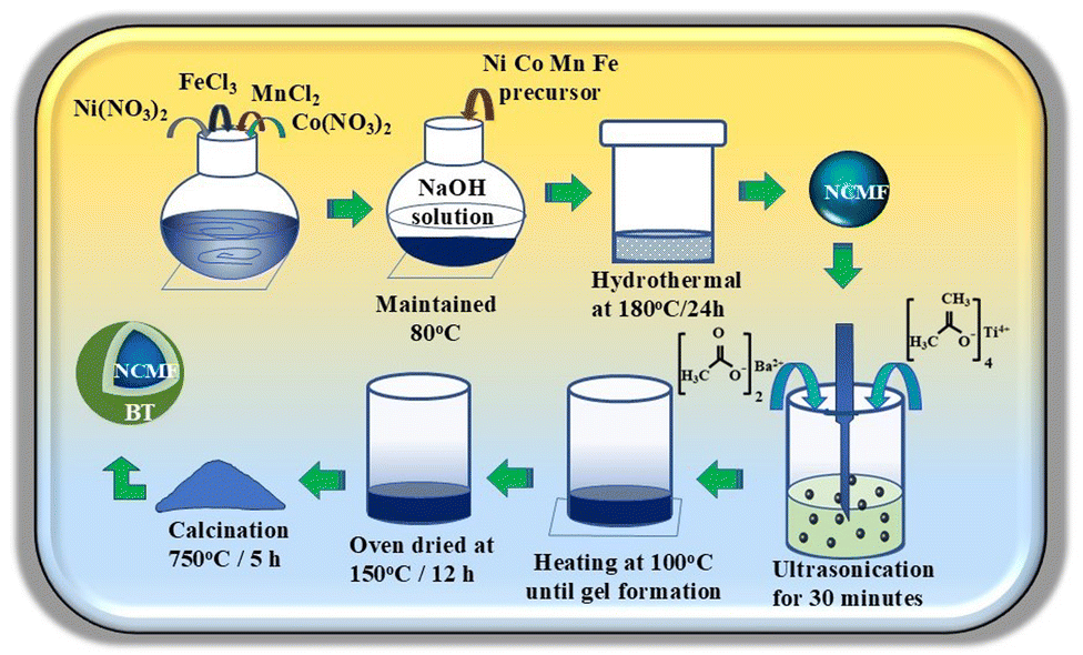 | ||
| Fig. 1 Schematic representation of the synthesis of the NCMF and NCMF@BT core–shell nanoparticles. | ||
Preparation of the flexible polyvinylidene fluoride (PVDF)-nanofiller composite film
N-Methyl pyrrolidone (NMP) and PVDF powder with a molecular weight of 275000 g mol−1 were purchased from Aldrich Chemicals, and used to create the flexible nanocomposite films. By dissolving varying concentrations of the PVDF powder in NMP solution, a highly viscous solution of PVDF was developed, and the viscosity was evaluated with a viscometer (Brookfield, DVNext cone/plate rheometer). Different volume percentages of NCMF@BT core–shell nanopowders were ultrasonically combined with the optimized viscous PVDF solution, and the resultant solution mixture was subsequently film-casted onto a glass plate using a doctor blade. After the excess solvent was removed from the cast film by heating it in an oven for three hours at 90 °C, a thick film of PVDF-NCMF@BT composites was achieved. Subsequently, the film was detached from the plate and employed for subsequent examination.
Characterisation
The crystalline structures of the synthesised nanopowders and the polymer composites were identified by employing X-ray diffraction (XRD, Rigaku miniflex 600) with Cu Kα (λ = 1.5406 Å) as the radiation source. The Raman spectra of the NCMF and NCMF-BT nanopowders were captured using a 785 nm excitation source and Renishaw in Via Raman Microscope. The morphology, size, and shape of the synthesised nanoparticles, as well as its dispersion in the PVDF matrix, were studied using a Zeiss EVO MA-10 scanning electron microscope (SEM). An Asylum Research MFP3D scanning probe microscope was utilised for magnetic force microscope (MFM) imaging. High-resolution transmission electron micrographs (HRTEM) were recorded using JEOL JEM-200FS FETEM. Magnetic properties of the filler particles and composite films were examined using PPMS (Quantum Design DynaCool). JEOL JEM-200FS FETEM was used to capture the high-resolution transmission electron micrographs (HRTEM).The nanocomposite films were coated with silver paste on both surfaces, each with an area of 1 cm2. Copper leads were then attached to the coated area and utilized for dielectric measurements. The dielectric measurements were conducted using the HIOKI, IM3523 LCR meter within the frequency range of 60 Hz to 200 kHz. The magnetodielectric measurements were conducted by placing the silver-coated samples in the centre of an electromagnet. Adjacent to the sample, a hall probe was positioned to measure the magnetic field generated by the electromagnet. A wide range of frequencies was used to test the capacitance (Cp), dielectric loss (tan d), and resistance (Rp) at each external magnetic field strength, which varied from 0 to 1000 G by adjusting the current provided to the electromagnet.
Results and discussion
The viscosity of the initial PVDF-NMP solution plays the most crucial role in producing well dispersed, flexible, and free-standing thick films of the PVDF-ceramic 0–3 composite. Although the filler particles can disperse more uniformly while mixing in a low viscous solution, they are more likely to clump together during the casting process. Additionally, because of their relatively higher density, they tend to settle at the bottom of the film, leaving a thin layer of PVDF on top. On the other hand, if the PVDF solution is excessively viscous, adding nanopowders to it will make it even more viscous, preventing the uniform distribution of filler particles in the PVDF matrix, and perhaps causing the polymer to lose its flexibility. Therefore, it is necessary to optimise the viscosity of the PVDF solution to prevent settling and to encourage the homogeneous dispersion of filler particles in the polymer matrix. Fig. 2 shows the variation in the viscosity of the PVDF-NMP solution with different concentrations of PVDF. The value of the viscosity was found to increase with the PVDF concentration, and nearly attained saturation at 0.1 g ml−1. The PVDF concentration of 0.15 g ml−1 in NMP solvent was chosen, so as to disperse the filler particles uniformly. It could keep the particles intact in the polymer matrix without agglomeration during the process of casting.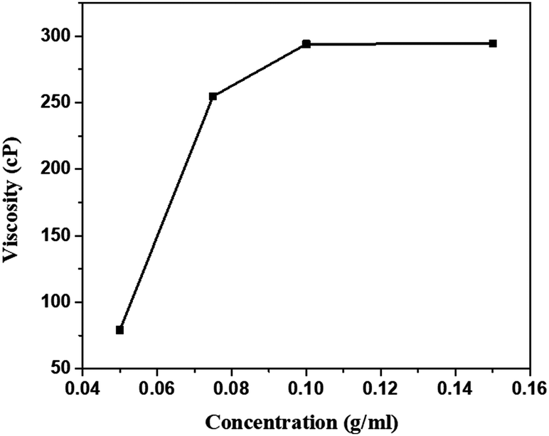 | ||
| Fig. 2 Viscosity with respect to the concentration of PVDF in the NMP solution. | ||
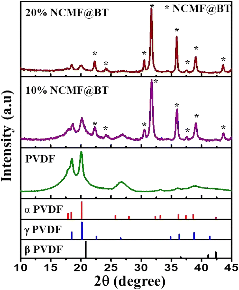
Fig. 3(a)–(c) shows the XRD patterns of NCMF, BT and NCMF@BT nano powders, respectively. The XRD pattern corresponding to NCMF is shown in Fig. 3 (a). Based on the JCPDS file no. 77-042 6, the peaks were indexed and the pattern depicts the cubic spinel ferrite structure with the space group of Fd3m (227).25 The phase purity and the crystal structure of the sol–gel synthesised BT calcined at 750 °C were analysed from the XRD pattern shown in Fig. 3(b). All the peaks were identified and indexed based on the ICDD pattern no. 31-0174, corresponding to the perovskite structure of BT.27 Barium titanate may exist as the cubic, tetragonal, rhombohedral or orthorhombic phase, or as a mixture of phases with one phase being predominant at room temperature. In general, the peak splitting at 45° 2θ depicts the tetragonal symmetry of BT, which corresponds to the (hkl) planes (002) and (200), whereas the rhombohedral/cubic BT shows a single peak at around 45° that refers to the (200) or (002) plane, respectively.28 In BT, below the Curie temperature, the tetragonal phase coexists with the rhombohedral/cubic phases. The peak at 45° in the case of the NCMF@BT nanopowder is shown in the inset figure in Fig. 3. A broader peak without any peak splitting is observed from the figure, which may be attributed to the coexistence of different phases. Better insight of the structure of BT can be obtained from the Raman spectroscopic investigation, which demonstrates the unique vibrations for the tetragonal and rhombohedral symmetries, as explained in the following section. Fig. 3(c) shows the X-ray diffractogram of the core–shell powder calcined at 750 °C for 5 h. The peaks corresponding to the ferrite phase are marked as F, and that of barium titanate as B. It is obvious from a comparison with Fig. 3(a) and (b) that the Bragg peak demonstrates the presence of both BT (shell) and NCMF (core) phases in the composite without the presence of any other impurity phases. This demonstrates unequivocally that even when the composite powder is subjected to high temperature calcination at around 750 °C, both NCMF and BT continue to exist as distinct phases without the formation of any additional phase.
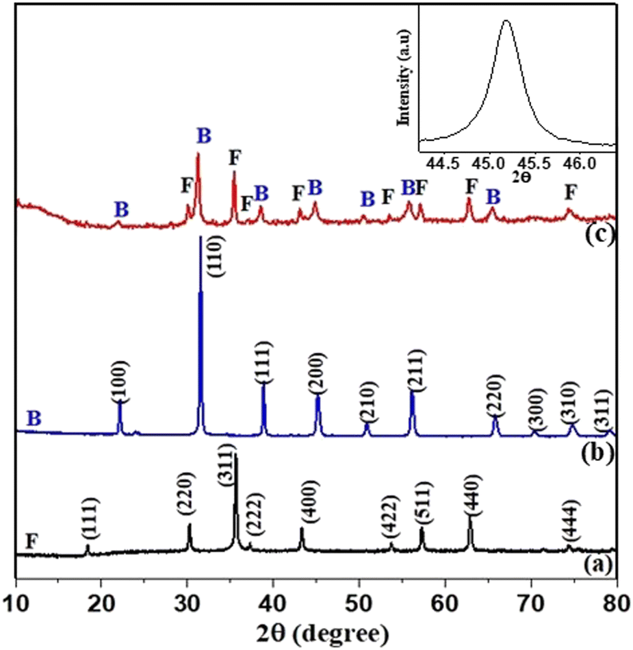 | ||
| Fig. 3 XRD pattern of (a) NCMF, (b) BT, (c) NCMF@BT nano powders, and the inset graph shows the XRD of NCMF@BT at 45°. | ||
The Raman spectra of the NCMF@BT core–shell nanoparticles were compared with those of pure NCMF, as well as BT in Fig. 4(a)–(c). Fig. 4(a) shows the spectrum of barium titanate calcined at 750 °C for 5 h. The band at 259 cm−1 corresponds to E-transverse optic (TO) mode, while a sharp peak at 306 cm−1 depicts the E (TO + longitudinal optic (LO)) mode, which is also considered as the characteristic peak for the tetragonal phase of BT. An asymmetric peak at 518 cm−1 and a broad peak at 715 cm−1 refer to the E(TO) and E(LO) vibrational modes of polar BT, respectively.29,30 The rhombohedral phase of BT is characterized by the existence of triple mode bands at 114 cm−1, 155 cm−1, and 187 cm−1 in the lower wavenumber region, with a distinct peak at 114 cm−1. The band at 518 cm−1 also corresponds to the E(TO) frequency modes of the rhombohedral BT phase.31,32 The whole spectrum of pure BT indicates that barium titanate exists as a composite mixture of both rhombohedral and tetragonal structures, which is also clearly evident from the XRD pattern shown in Fig. 3(b).
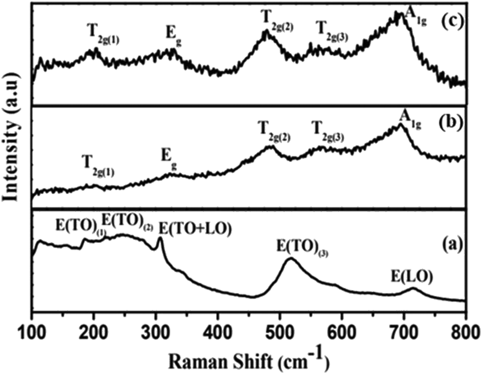 | ||
| Fig. 4 Raman spectrum of (a) BT, (b)NCMF and (c) NCMF@BT nanoparticles. | ||
The Raman spectrum of NCMF is shown in Fig. 4(b). Five Raman-active modes corresponding to the FeO6 octahedra and FeO4 tetrahedra have been predicted from group theory for the Fd![[3 with combining macron]](https://www.rsc.org/images/entities/char_0033_0304.gif) m (227) space group.33 The bands at 200, 480 and 571 cm−1 correspond to the T2g mode, while the 322 cm−1 peak refers to Eg and 695 cm−1 to the Ag modes of NCMF. Fig. 4(c) shows the Raman spectrum of the NCMF@BT core–shell nano powders synthesised by sol–gel technique. The Raman modes corresponding to NCMF are mainly present in the spectrum, while the peaks corresponding to BT are less prominent. However, the intensities of the peaks at 322 cm−1 and 200 cm−1 are relatively higher and broader compared to that of monolithic NCMF. The presence of Raman modes of BT near 183 cm−1 and 306 cm−1 could increase the relative intensities of the aforementioned peaks.29 The formation of a core–shell structure with NCMF as the core, and finer and dispersed nanoparticles of BT around the NCMF as the shell, might be the cause of the predominant peaks of NCMF. Meanwhile, owing to the nanosize effect, the signals from the Raman modes corresponding to BT are considerably reduced. The phonon confinement and differences in phonon relaxation with particle size are attributed to this broadening of the Raman lines in the core–shell nanoparticles. Furthermore, the small particle size prevents phonon propagation and causes Brillouin zone folding, which makes all phonons Raman-active, resulting in the broadening of the Raman spectrum.30,33
m (227) space group.33 The bands at 200, 480 and 571 cm−1 correspond to the T2g mode, while the 322 cm−1 peak refers to Eg and 695 cm−1 to the Ag modes of NCMF. Fig. 4(c) shows the Raman spectrum of the NCMF@BT core–shell nano powders synthesised by sol–gel technique. The Raman modes corresponding to NCMF are mainly present in the spectrum, while the peaks corresponding to BT are less prominent. However, the intensities of the peaks at 322 cm−1 and 200 cm−1 are relatively higher and broader compared to that of monolithic NCMF. The presence of Raman modes of BT near 183 cm−1 and 306 cm−1 could increase the relative intensities of the aforementioned peaks.29 The formation of a core–shell structure with NCMF as the core, and finer and dispersed nanoparticles of BT around the NCMF as the shell, might be the cause of the predominant peaks of NCMF. Meanwhile, owing to the nanosize effect, the signals from the Raman modes corresponding to BT are considerably reduced. The phonon confinement and differences in phonon relaxation with particle size are attributed to this broadening of the Raman lines in the core–shell nanoparticles. Furthermore, the small particle size prevents phonon propagation and causes Brillouin zone folding, which makes all phonons Raman-active, resulting in the broadening of the Raman spectrum.30,33
The influence of the filler particle on the crystalline phase of PVDF was studied from the XRD pattern of its composites with varying filler concentration. Fig. 5 compares the X-ray diffraction pattern of the PVDF-NCMF@BT composites at 10 and 20 volume percentages of commercial PVDF powder, as well as the JCPDS patterns of the α, β and γ crystalline phases of PVDF. The JCPDS card no. 42-1650, 42-1649 and 38-1638 [25] corresponding to the α, β and γ phases of PVDF, respectively, are shown at the bottom of Fig. 5. Both the α and γ phases of PVDF possess a monoclinic crystal structure, resulting in a comparable XRD pattern. The Bragg peak observed 2θ = 17.71° degrees represents the reflection from the (100) plane of the α phase of PVDF. However, the γ phase does not exhibit a peak at 17.71°.
 | ||
| Fig. 5 X-ray diffraction patterns of the PVDF powder, PVDF-10 vol% NCMF and PVDF-20 vol% NCMF with different volume percentages of NCMF@BT nano powders with the JCPDS patterns of different phases of PVDF. | ||
The X-ray diffraction (XRD) pattern of the PVDF powder (Fig. 5) shows clear and identifiable Bragg peaks at 17.71°, 18.41°, 20.01° and 26.61°. Upon comparison with the JCPDS patterns, it is evident that both α and γ phases were present in their inherent state. The analysis of 10 vol% NCMF@BT nanopowders revealed that PVDF existed as a mixed phase consisting of both α and γ forms. However, the XRD pattern of 20 vol% NCMF@BT clearly depicts that the intensity of the peak at 17.71° was considerably reduced, while the intensity of the peak at 18.41° became more prominent, indicating that the ferroelectric γ phase is growing at the expense of the α phase. This clearly shows that the interaction between the NCMF@BT nanoparticles and the PVDF matrix induced the growth of the γ phase in the PVDF matrix.
The SEM microstructures of the NCMF and NCMF@BT core–shell nanopowders are compared in Fig. 6(a) and (b) at the same magnification. Fig. 6(a) shows a narrow size range of particles with an average particle size of 80 nm. Fig. 6(b) shows a comparable particle distribution with a 150 nm average size. Furthermore, it is clear from the micrographs that no distinct phase is seen, demonstrating that BT crystallites have developed on the NCMF nanoparticles and do not exist as a distinct phase. The observation is further supported by the use of magnets to draw the particles together. The results confirmed that all of the particles are attracted by the magnet without leaving behind any residual phase of BaTiO3. The inset shows the photograph of all the core–shell particles being attracted by the magnet. An in-depth view of the core–shell morphology of the nanoparticles has been analysed using HRTEM.
 | ||
| Fig. 6 SEM micrograph of (a) NCMF and (b) NCMF@BT nanopowders. The inset shows the core–shell nanopowders attracted by magnet. | ||
The microstructure of the core–shell nanoparticles was analyzed using HRTEM and MFM micrographs, as depicted in Fig. 7(a)–(e). A typical TEM image of the core–shell nanoparticles is shown in Fig. 7(a), while a high-resolution image of a single nanoparticle is shown in Fig. 7(b), confirming the existence of the core–shell structure. The interface between the two phases in the TEM images can be distinguished by the difference in the transmission intensities for NCMF and BaTiO3.
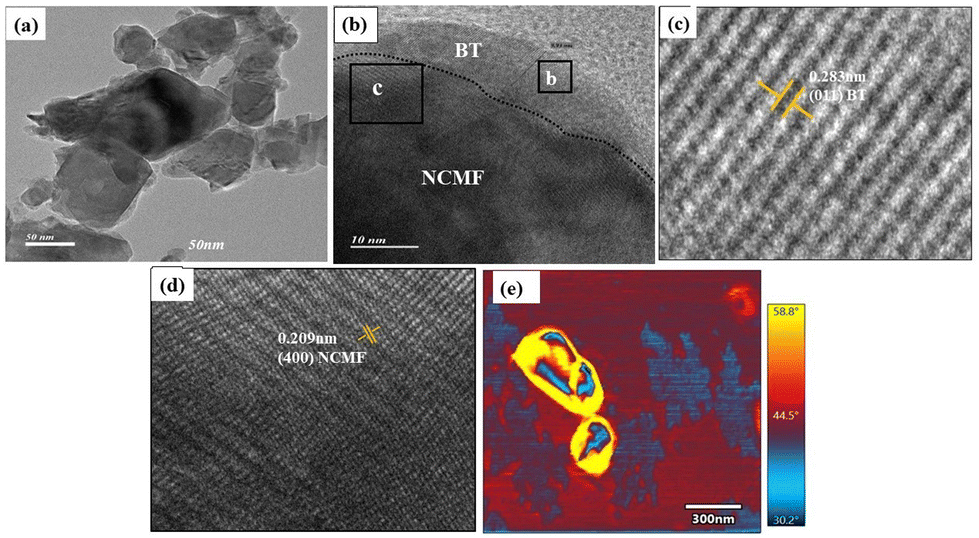 | ||
| Fig. 7 HRTEM micrograph of the (a) NCMF@BT core–shell nanoparticles, (b) single core–shell nanoparticle, the enlarged view of the (c) shell, (d) core region, and (e) MFM image of the core–shell nano particles. | ||
Fig. 7(c) and (d) shows the enlarged image of the shell and core region, exhibiting clearly defined lattice fringes that point to the particles' nanocrystalline structure. The interplanar spacing measured from the shell region is found to be 0.283 nm, which agrees well with the d-spacing corresponding to the (011) plane of BaTiO3,34 whereas the core region showed fringes of overlapped planes of both NCMF and BT. In addition to 0.238 nm, the core region showed a fringe width of 0.209 nm, corresponding to the (400) plane of the NCMF phase.35 The MFM image of the agglomerates of the nanoparticles shown in Fig. 7(e) clearly depicts the core–shell microstructure, where the polarised blue grains of NCMF embedded in the non-magnetic BaTiO3 phase are indicated by the yellow region.
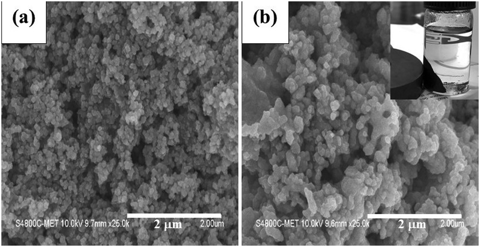
Fig. 8(a) and (b) shows the variation in the particle distribution at lower and higher filler concentrations. The SEM micrographs of 10 vol% and 50 vol% PVDF-NCMF@BT core–shell powders are compared. At lower volume percentage (Fig. 8(a)), the particles are highly dispersed in the matrix as the filler concentration is very low. Eventually, their interparticle distances are higher. However, when the vol% of NCMF@BT is increased, the number of particles per unit volume becomes significantly higher, resulting in a dense distribution of particles within the polymer matrix. Hence, in order to investigate the filler distribution and interaction with the polymer matrix, the lower (10%) and higher filler loading (50%) were chosen and compared in Fig. 8(a) and (b), respectively.
 | ||
| Fig. 8 SEM micrographs of PVDF with (a) 10 vol% NCMF@BT, (b) 50 vol% NCMF@BT, and cross-sectional view of the (c) PVDF-50% NCMF@BTcomposites. | ||
Well embedded and broadly distributed nanoparticles were observed in the composite containing 10 vol% of filler nanoparticles, while a highly dense and close proximity of particles are observed at 50 vol%. It is also clear from Fig. 8(a) and (b) that the particles showed good interaction with PVDF even upon higher filler loading. Fig. 8(c) shows the cross-sectional view of the free-standing film containing 50 vol% of NCMF@BT nanopowders with PVDF, and the films thickness measured from the micrographs was about 110 μm. The inset figure of Fig. 8(c) displays the image of the self-standing film made of PVDF–50% NCMF composite. The flexibility of the film is readily apparent, as depicted in the image (Fig. 8(c) inset).
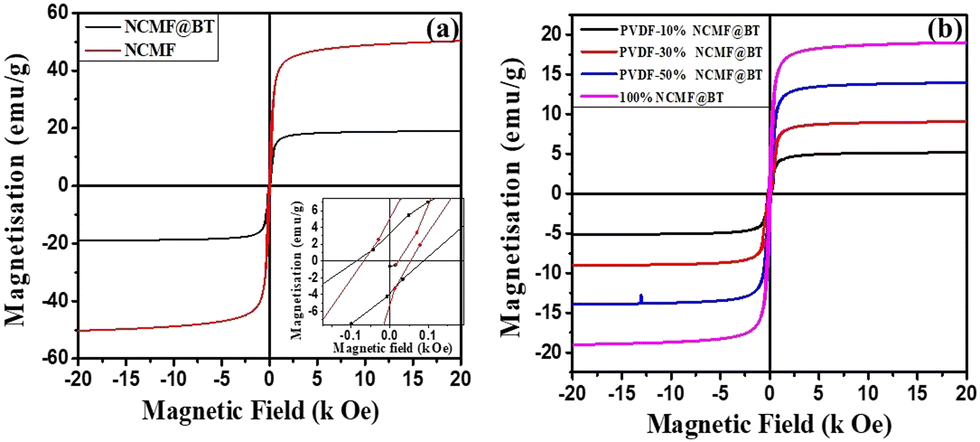
Fig. 9(a) compares the M–H hysteresis loops of the NCMF and NCMF@BT core–shell nanopowders plotted in the field range of ±20 kOe to explore the ferrimagnetic behaviour of the NCMF and NCMF@BT core–shell nanopowders. Fig. 9(b) shows the variation in the magnetisation behaviour of the PVDF-NCMF@BT composites at different volume percentages when it was dispersed in the PVDF matrix. It is evident from Fig. 9(a) that the hysteresis behaviour of both NCMF and NCMF@BT nanopowders displayed a typical ferrimagnetic character, which supports the existence of long-range magnetic ordering in both phases. However, the magnetic saturation falls from 48.46 emu g−1 to 18.76 emu g−1, and the remanence decreases from 5.07 emu g−1 to 3.32 emu g−1 for NCMF@BT nanoparticles when compared to that of pure NCMF. On the contrary, Fig. 9(a) depicts that the coercivity (Hc) of the core–shell nanoparticles are higher than that of monolithic NCMF, despite the presence of the thin ferroelectric BT shell phase covering each NCMF particle. The inset of Fig. 9(a) clearly shows that Hc increased from 67.06 Oe to 86.85 Oe for the NCMF@BT core–shell nanoparticles. The pinning action of the spins of NCMF at the NCMF-BT interfaces can account for these reversed experimental results. Due to many nucleation sites that formed the BT shell during heterogeneous nucleation, the NCMF-BT interface exhibits a significant amount of lattice misfit between NCMF and BT. Such misfit at the interfaces frequently results in a high strain and energy, which can pin the spin rotation at the interface of the NCMF nanoparticles and increase the coercivity of the core–shell nanopowders.36,37
 | ||
| Fig. 9 Magnetic field (Oe)-dependent magnetization (emu g−1) of (a) NCMF and NCMF@BT nanoparticles, (b) PVDF with different volume percentages of NCMF@BT nanopowders. | ||
Fig. 9(b) illustrates the hysteresis characteristics of the PVDF composites containing varying volume percentages of NCMF@BT nanopowders. For more accurate comparison, the differences in the magnetic behaviour of the composites are tabulated in Table 1. The data shown in Table 1 unequivocally illustrates that when the concentration of filler increases, the values of the saturation magnetization (Ms) and remanence (Mr) of the composites also followed a similar pattern. The squareness ratio (Mr/Ms) of the composites, as shown in Table 1, indicates that the ratio is lower than 0.5 (the ideal value for randomly oriented particles) for both composites at all vol% and the NCMF@BT core–shell nanoparticles.
| Composition | M s emu g−1 | M r emu g−1 | H c Oe | M r/Ms |
|---|---|---|---|---|
| 10 vol% NCMF@BT | 5.08 | 1.16 | 195.66 | 0.228 |
| 30 vol% NCMF@BT | 8.92 | 2.29 | 144.12 | 0.257 |
| 50 vol% NCMF@BT | 13.95 | 3.25 | 90.92 | 0.233 |
| 100% NCMF@BT | 18.76 | 3.32 | 86.85 | 0.177 |
The magnetization in the PVDF-NCMF@BT composite is solely attributed to the NCMF phase. Therefore, the enhancement of the magnetic characteristics of the composites is directly proportional to the rise in the concentration of the magnetic nanoparticles that substitute the polymer matrix. Each individual grain of ferrite functions as a center of magnetization, and the resulting magnetism is the combined vector sum of the magnetizations of all the grains.38 There are two distinct forms of interaction that occur in magnetic nanoparticles and their nanocomposites—intra-particle exchange interaction and interparticle dipolar coupling. The exchange interaction enhances remanence, but the dipolar coupling diminishes it. The reduced remanence values observed in both nanocomposites and nanopowders indicate that dipolar interaction is the primary factor influencing the interactions. Furthermore, the exchange interaction is a quantum mechanical phenomenon that is predominant in hard magnetic materials,39 thus proving that the composites exhibit excellent soft magnetic behavior and improved switching properties. Table 1 also reveals that the value of Hc is maximum for the lowest filler loading, which is 10 vol% NCMF@BT. As the volume percentage of the filler nanoparticles increases, the magnitude of Hc decreases. The presence of a non-magnetic polymer layer amid the magnetic nanoparticles disrupts the magnetic interaction between the particles, resulting in an enhanced coercivity value in these composites.40,41 At smaller volume percentages, the distance between the particles is greater, resulting in a higher effective anisotropy barrier.42 This reduces the dipolar coupling between the particles, necessitating a higher magnetic field to cancel out the internally oriented dipoles. As a result, the coercive (Hc) value is increased. With the increased filler loading, the closer proximity between the particles significantly decreases the anisotropy barrier energy and encourages stronger magnetic interaction between the neighboring particles. This results in faster relaxation and lower coercivity.43,44 A more detailed investigation on the domain distribution in the composites was conducted using MFM with variable magnetic field.
The MFM equipped with the lift mode feature was utilised to capture the topography, amplitude, and phase images of the composite film. In order to obtain high-quality images without any artifacts, all MFM tests were conducted using a lift height of 50 nm. A range of magnetic fields between 0 Oe ± 4000 Oe was applied to the nanocomposite films, and their corresponding MFM micrographs were generated to study the impact of the cores-shell microstructure on the magnetic field distribution in the composite. Fig. 10 depicts the MFM micrographs of the composite containing 50 vol% of NCMF@BT core–shell nanopowders at 0 Oe, ±1000 Oe and ± 4000 Oe. The microstructure captured at 0 Oe showed a band of blue and yellow regions, instead of a well-defined polarised grain. The masking effect of both PVDF and BT could lead to such microstructure. Even yet, the MFM tip was able to detect the stray field produced by the core NCMF nanoparticles, which was visible as the randomly distributed dotted blue domains in the yellow band, as seen in Fig. 10 at 0 Oe. As the field increased up to 4000 Oe, the following microstructural variations were observed from Fig. 10. A greater number of dotted blue domains evolved with the field, and the size and contrast of the persisting domains also increased with the field. As a result, the bright (yellow) region depicting the repulsive force (due to the encapsulated BT phase) experienced by the MFM tip grew around the newly evolved oriented domains. Furthermore, it is also evident that the domains did not return to their initial state when the field reversed to 0 Oe. Rather, the oriented blue domains became more prominent and expanded with the field. This shows that an irreversible domain wall movement has occurred when an external magnetic field was applied and removed. This implies that the domain wall pinning at the interface between NCMF and BT did not revert the domain alignment back to the original state.17,45 This further justifies and supports the existence of barium titanate as encapsulation around the NCMF nanoparticles, which eventually enhanced the coercivity of the composite. To apparently view the domain distribution, a 3-dimensional view of the MFM image of 50% NCMF@BT composites at −3000 Oe is shown in Fig. 10(b). Fig. 10(b) depicts dense but isolated small oriented domains of NCMF. This demonstrates unequivocally that the geometrical restriction imposed by the surrounding BT phase confined the spins of the NCMF nanoparticles into small islands,46 further confirming the core–shell microstructure of the nanoparticles.
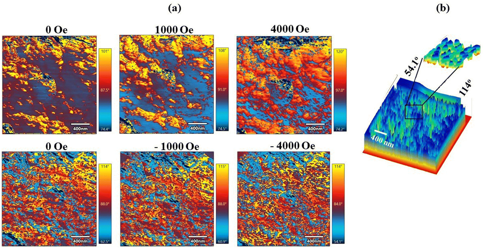 | ||
| Fig. 10 MFM images of the (a) PVDF-50% NCMF@BT composite at varying external fields between ±3000 Oe, and (b) 3-dimensional view of 50% NCMF@BT at – 3000 Oe. The length of the scale bar denotes 400 nm in all the figures. | ||
In ferroelectric and ferrimagnetic composites, the interaction between the two ferroic orders plays a crucial role in determining the magnetoelectric behavior. Magnetodielectric measurements have been demonstrated as an effective method for analysing the level of interaction between magnetic and electric polarisations.41 The diversity in the microstructure of the PVDF-NCMF@BT composite systems inspired us to investigate the magnetocapacitance response. The magnetocapacitance (MC) and magnetoresistance (MR) of the composites are determined by applying the equations provided below:47,48
 | (1) |
 | (2) |
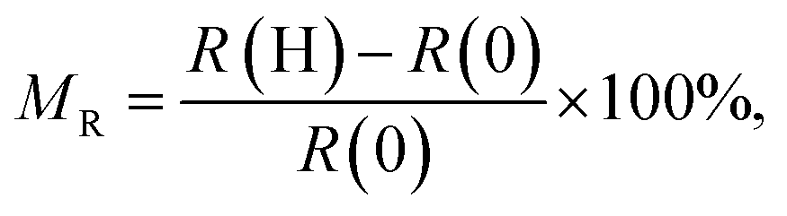
Fig. 11(a) and (b) displays the change in the capacitance and resistance spectra of PVDF-50 vol% NCMF@BT nanopowders, respectively. These changes were measured at room temperature in the frequency range of 0.1–200 kHz and magnetic field range of 0 Oe to 1000 Oe. Furthermore, the magnetic field was applied in a direction parallel to the surface of the film. Fig. 11(a) shows that the value of the capacitance decreased with the increase in frequency. It is also obvious from Fig. 11(a) that the capacitance falls precipitously at lower frequencies, and the pace is considerably reduced toward higher frequency. The expanded view of the capacitance spectra shown in the inset of Fig. 11(a) clearly demonstrates that the magnitude of capacitance of the composite increased with the increase in magnetic field. The variation in the resistance with a frequency of PVDF-50 vol% NCMF@BT, shown in Fig. 11(b), also followed a similar pattern as that of the capacitance spectra. However, the inset depicts that the resistance of the composite decreased with the magnetic field. The significant capacitance and resistance observed at lower frequencies are attributed to the contribution of the atomic, ionic, and electronic polarizations. Maxwell–Wagner interfacial polarization, which occurs between the NCMF, BT, and PVDF phases, along with electrical charge depletion, are additional factors that can impact the capacitance.49
 | ||
| Fig. 11 Variation in the (a) capacitance, (b) resistance, and (c) dielectric loss with frequency of the PVDF-50 vol% PVDFCMF@BT nanocomposites under various magnetic fields. The inset figures are their corresponding magnified images. | ||
Due to the ability of all polarizations to align themselves successfully with the electric field at the low frequency range, the cumulative input of all the polarization leads to a higher magnitude capacitance and resistance at lower frequencies. As the frequency increases, the space charge and interfacial polarizations are initially unable to align themselves more effectively with the electric field. This is followed by the dipolar and ionic polarizations, resulting in an exponential decrease in their magnitude. Only the electronic polarization contributes to the dielectric characteristics of the composite in the higher frequency range. Therefore, their values become stable as the frequency increases.50,51Fig. 11(c) compares the variation in the dielectric loss with frequency of PVDF-50 vol% NCMF@BT composite recorded in the frequency range of 0.1–200 kHz at different magnetic field range values from 0 Oe to 1000 Oe. The composites showed a decrease in loss with frequency and increase with the applied magnetic field (Fig. 11(c) inset), following the same trend as that observed in the case of capacitance. The higher loss at low frequency is due to the combined contribution of all four types of polarisations, and their gradual relaxation towards higher frequency range leads to the gradual decrease in dielectric loss.50 Even at such higher filler loading, the dielectric loss is considerably low for the PVDF-NCMF@BT composites throughout the frequency range. This clearly demonstrates the advantage of the existence of BT as an encapsulation around the NCMF nanoparticles, instead of as a separate particle in the composite. The surrounding BT phase could effectively contain the induced charge/voltage within the ferrite nanoparticles, and prevent the generation of short circuit paths between the nearest neighbouring grains of high loss and higher conductive NCMF nanoparticles. In turn, this could effectively polarise the piezoelectric BT phase without getting shorted. The core–shell microstructure also ensures the effective transfer of the induced strain between the two ferroic phases. Moreover, it was possible to effectively transfer the strain created in the ferrimagnetic phase to the surrounding BT phase. Hence, by taking advantage of its low dielectric loss characteristics, the BT phase here served as both the piezoelectric phase and the insulating layer.
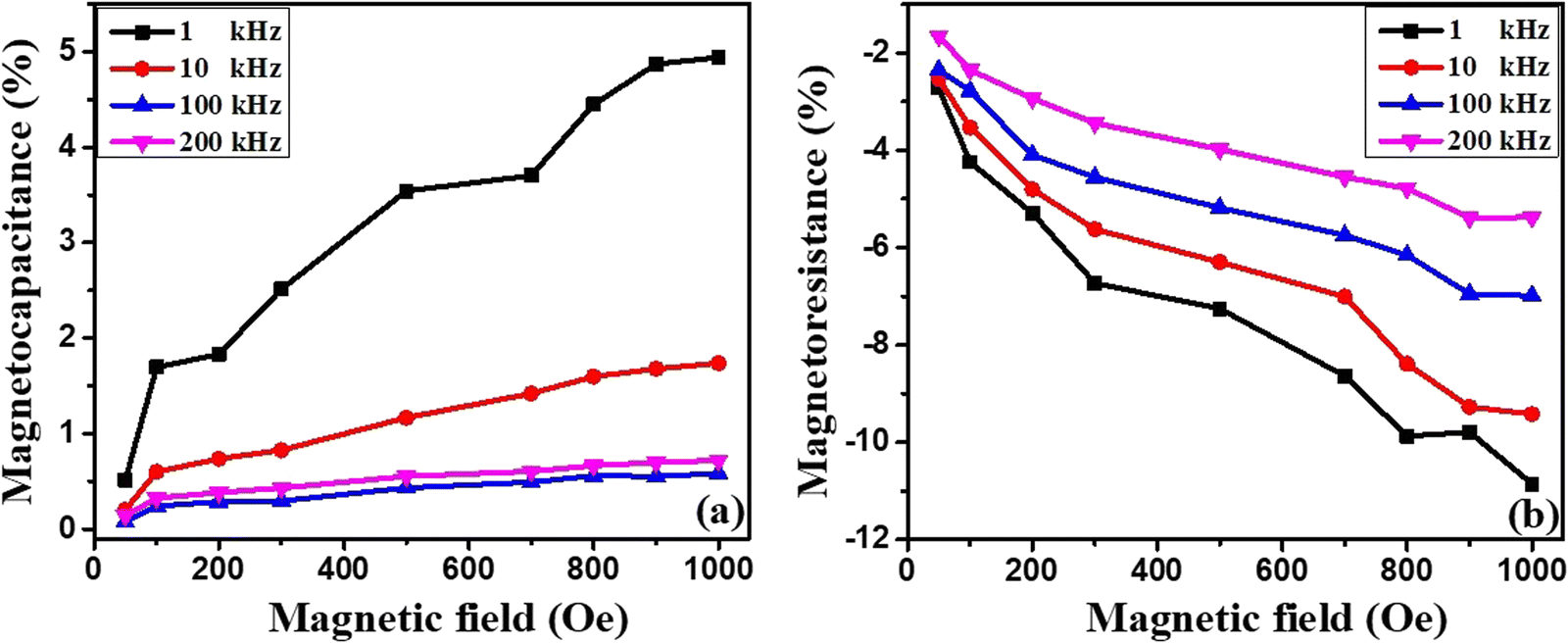
The magnetocapacitance response of the PVDF-50 vol% NCMF@BT composite system with varying magnetic fields and frequencies of 1, 10, 100 and 200 kHz is shown in Fig. 12(a). It has been observed that the MC values of the composites increased with the magnetic field, showing a positive coupling with the field. Furthermore, high values of MC are observed at 1 kHz, and their magnitude decreases with the increase in frequency. However, the values decreased up to 100 kHz. At 200 kHz, the composite showed a slight increase in the coefficient. By comparison, the MR values of the 50 vol% NCMF@BT composite decreased with the magnetic field, depicting a negative coupling coefficient. Similar to MC, the MR values of the composite show a decreasing trend with negative values for all frequencies under investigation. However, in contrast to MC, the values of MR steadily decreased with frequency without any reversal.
 | ||
| Fig. 12 Variation in the (a) magnetocapacitance and (b) magnetoresistance with the magnetic field at different frequencies of PVDF-50 vol% NCMF@BT composite. | ||
The underlying cause of the magnetocapacitance behaviour in the current PVDF-NCMF@BT composite systems can be elucidated by various perspectives. The interfacial polarization effect and interface or core-dominated magnetoresistance in the magnetodielectric composite systems result in a magnetocapacitance response. This response is based on the resistance of the conducting grain or grain boundary when a magnetic field is applied. The magnetostrictive strain induced in the magnetic material by the applied magnetic field also alters the magnetocapacitance of the composite through mechanical coupling. The dominant mechanism determines whether the coefficient of MC is positive or negative.52 Due to the existence of barium titanate as a thin shell around the NCMF nanoparticles, as well as the homogeneous distribution of filler particles in the PVDF matrix, the intrinsic field generated by the NCMF nanoparticles could effectively induce polarisation in the surrounding BT phase. Hence, under a magnetic field, the strong interaction between the NCMF core and BT shell led to a positive MC effect in the composites.51,53 As both capacitance and resistance are inversely related, the magnitude of the MR coefficient showed a negative coupling with the magnetic field. Moreover, the thin insulating layers of BT and PVDF between the closely packed ferrimagnetic NCMF nanoparticles function as tunnelling barriers.47 In such granular systems, spin-disordered grain boundaries exist between the magnetic particles and their surrounding non-magnetic phase. These spin disorders at the surface of the nanoparticles further degrade the spin-polarisation of the enclosed phase. When such systems are subjected to a magnetic field, the disordered surface region spin gradually aligns with the direction of the magnetic field, which eventually promotes spin-polarised tunnelling. In turn, this leads to a gradual decrease in resistance and increase in dielectric loss (Fig. 11(c)) of the composite.54 A consistent observation has been made in many literature studies and extensively addressed, focusing on the substantial interfacial mechanical interaction between the dielectric and magnetic phases.52,55,56
Fig. 12 demonstrates that at a frequency of 1 kHz, the PVDF-50 vol% NCMF@BT composite exhibits significant MC and MR values of 1.7% and −4.2% at 100 Oe, respectively. These values grow with the strength of the magnetic field, and reach a maximum of 4.9% and −10.8% at 1000 Oe. Table 2 compares the values of magnetocapacitance (MC) and magnetoresistance (MR) reported in other literature studies with the current work. Although a higher magnitude of MC is reported in ceramic-based composites, a higher field is required to attain that value. Overall, polymer-based composites had lower MC values. However, the filler nanoparticles with a core–shell microstructure exhibited improved MC values. In terms of MR values, polymer – ferrite composites showed a higher magnitude of MR, but a higher magnetic field is necessary to achieve such a high value. The PVDF-NCMF@BT flexible composites reported in the present work showed significant MC and MR magnitudes at 100 Oe, and their sensitivity was further improved with the applied magnetic field. These unique properties make the composite an excellent choice for use in electronic and spintronic devices, supercapacitors, and devices for the magnetically enhanced capacitive deionization of water.
| Composite system | Magnetocapacitance (%) | Magnetoresistance (%) | Magnetic field (Oe) | Ref. |
|---|---|---|---|---|
| BaTiO3–CoFe2O4 Core–shell bulk composite | ∼−4.5 | — | 21000 |
57 |
| BaTiO3–ZnFe2O4 Core–shell bulk composite | ∼−1.3 | — | 10000 |
58 |
| BaTiO3–Co0.5Zn0.5Fe2O4 bulk composite | ∼1.5 | — | 2680 | 52 |
| Fe3O4-PANI core–shell | — | ∼8.4 | 20000 |
59 |
| Fe3O4-polythiophene core–shell | — | ∼1.5 | 15000 |
60 |
| Fe3O4-PVA core–shell | — | ∼−8.4 | 5000 | 54 |
| ∼−10 | 15000 |
|||
| PVDF-NiFe2O4 | ∼−0.3 | — | 7000 | 61 |
| PVDF-Ni coated MWCNT | ∼3 | — | 2000 | 62 |
| P(VDF-TrFE)-La0.7Ba0.3MnO3 | ∼0.7 | — | 7000 | 63 |
| PVDF-50 vol% NCMF@BT | ∼1.7 | ∼−4.2 | 100 | Present work |
| ∼4.9 | ∼−10.8 | 1000 |
Conclusions
A simple synthesis method was used to obtain the NCMF@BT core–shell nanostructure. Eventually, flexible and free-standing thick films of PVDF with different volume percentages of NCMF@BT nanopowders were also fabricated. The TEM and SEM microstructures revealed the core–shell morphology and the distribution of fillers in the composite films. Furthermore, films with a thickness of around 110 μm were developed. The microstructure and magnetic structure were observed using a magnetic force microscope. The MFM images displayed well confined, densely packed, and separate nanodomains of NCMF. Furthermore, the recorded variable field MFM images depict the domain dynamics as a function of the external magnetic field with the magnetic NCMF at the core and non-magnetic BT/PVDF at the shell. With the proper isolation offered by BT encapsulation, the potential for charge leakage among the neighboring NCMF nanoparticles and the resulting dielectric loss are significantly reduced. The MC and MR spectra of the composites exhibited remarkable sensitivity, even at a magnetic field as low as 100 Oe. At a frequency of 1 kHz, remarkable MC and MR values of 1.7% and −4.2% were obtained at 100 Oe, respectively. These values further increased to a maximum of 4.9% and −10.8% at 1000 Oe for the PVDF-50 vol% NCMF@BT nanopowder composite.Author contributions
The author K. S. D. conceptualized the work, experimental design and characterization, investigation of the work, and preparation of the manuscript. B. R. and S. D. supported the MFM analysis. S. P. and V. L. M. provided support for the other magnetic and dielectric characterisations and analysis. V. L. M. and S. B. R. supervised the work, provided the resources, and reviewing and editing of the work. The experimental work was carried out under the mentorship of S. B. R.Data availability
The generated data are reported in the manuscript. However, raw data will be made available by the corresponding authors upon reasonable request.Conflicts of interest
The authors declare that they have no known competing interests in this work.Acknowledgements
This work is supported by DST-Women Scientist-A project under Grant No. SR/WOS-A/PM 76/2016 financed by the Department of Science and Technology (DST), India. K. S. Deepa would like to acknowledge DST-WOSA for the fellowship support. The author would like to thank CIF, Savitribai Phule Pune University for providing the magnetic measurements facility.References
- P. Martins and S. Lanceros-Méndez, Adv. Funct. Mater., 2013, 23, 3371–3385 CrossRef CAS.
- M. Y. Alnassar, Y. P. Ivanov and J. Kosel, Adv. Electron. Mater., 2016, 2, 1600081 CrossRef.
- A. Mooti, C. M. Costa, A. Maceiras, N. Pereira, C. R. Tubio, J. L. Vilas, S. Besbes-Hentati and S. Lanceros-Mendez, J. Mater. Sci., 2020, 55, 16234–16246 CrossRef CAS.
- K. S. Deepa, M. T. Sebastian and J. James, Appl. Phys. Lett., 2007, 91, 202904 CrossRef.
- J. D. Bobić, G. F. Teixeira, R. Grigalaitis, S. Gyergyek, M. M. V. Petrović, M. A. Zaghete and B. D. Stojanovic, J. Adv. Ceram., 2019, 8, 545–554 CrossRef.
- P. Martins, R. Gonçalves, S. Lanceros-Mendez, A. Lasheras, J. Gutiérrez and J. M. Barandiarán, Appl. Surf. Sci., 2014, 313, 215–219 CrossRef CAS.
- P. Martins, C. M. Costa, M. Benelmekki, G. Botelho and S. Lanceros-Mendez, CrystEngComm, 2012, 14, 2807–2811 RSC.
- A. C. Lopes, C. M. Costa, R. S. I. Serra, I. C. Neves, J. L. G. Ribelles and S. Lanceros-Méndez, Solid State Ion, 2013, 235, 42–50 CrossRef CAS.
- J. Thevenot, H. de Oliveira, O. Sandre, S. Lecommandoux, J. Thévenot and H. Oliveira, Chem. Soc. Rev., 2013, 42, 7099–7116 RSC.
- A. Alfadhel, B. Li, A. Zaher, O. Yassine and J. Kosel, Lab Chip, 2014, 14, 4362–4369 RSC.
- D. Ai, Y. Chang, H. Liu, C. Wu, Y. Zhou, Y. Han, H. Yu, B. Xiao, Y. Cheng, G. Wu and Z. Jia, Nano Res., 2024, 17, 8504–8512, DOI:10.1007/s12274-024-6793-0.
- K. S. Deepa, M. S. Gopika and J. James, Compos. Sci. Technol., 2013, 78, 18–23 CrossRef CAS.
- K. S. Deepa, P. L. Priyatha, P. Parameswaran, M. T. Sebastian and J. James, Ceram. Int., 2010, 36, 75–78 CrossRef CAS.
- S. Premkumar, E. Varadarajan, M. Rath, M. S. Ramachandra Rao and V. L. Mathe, J. Eur. Ceram. Soc., 2019, 39, 5267–5276 CrossRef CAS.
- D. Ai, C. Wu, Y. Han, Y. Chang, Z. Xie, H. Yu, Y. Ma, Y. Cheng and G. Wu, J. Mater. Sci. Technol., 2025, 210, 170–178 CrossRef.
- D. Ai, Y. Han, Z. Xie, X. Pang, Y. Chang, H. Li, C. Wu, Y. Cheng and G. Wu, Nano Res., 2024, 17, 7746–7755, DOI:10.1007/s12274-024-6765-4.
- U. Hartmann, Annu. Rev. Mater. Sci., 1999, 29, 53–87 CrossRef CAS.
- S. H. Xie, Y. M. Liu, X. Y. Liu, Q. F. Zhou, K. K. Shung, Y. C. Zhou and J. Y. Li, J. Appl. Phys., 2010, 108, 054108, DOI:10.1063/1.3481459.
- F. Zavaliche, H. Zheng, L. Mohaddes-Ardabili, S. Y. Yang, Q. Zhan, P. Shafer, E. Reilly, R. Chopdekar, Y. Jia, P. Wright, D. G. Schlom, Y. Suzuki and R. Ramesh, Nano Lett., 2005, 5, 1793–1796 CrossRef CAS PubMed.
- G. Caruntu, A. Yourdkhani, M. Vopsaroiu and G. Srinivasan, Nanoscale, 2012, 4, 3218–3227 RSC.
- S. Guo, X. Duan, M. Xie, K. C. Aw and Q. Xue, Micromachines, 2020, 11, 1076, DOI:10.20944/preprints202011.0262.v1.
- L. Wu, Z. Jin, Y. Liu, H. Ning, X. Liu, Alamusi and N. Hu, Nanotechnol. Rev., 2022, 11, 1386–1407 CrossRef CAS.
- A. Gupta and R. Chatterjee, J. Appl. Phys., 2009, 106, 024110, DOI:10.1063/1.3181061.
- L. G. van Uitert, J. Chem. Phys., 1956, 24, 306–310 CrossRef CAS.
- P. A. Shaikh, R. C. Kambale, A. V. Rao and Y. D. Kolekar, J Alloys Compd., 2009, 482, 276–282 CrossRef CAS.
- B. Jiang, J. Iocozzia, L. Zhao, H. Zhang, Y. W. Harn, Y. Chen and Z. Lin, Chem. Soc. Rev., 2019, 48, 1194–1228 RSC.
- H.-W. Lee, S. Moon, C.-H. Choi and D. K. Kim, J. Am. Ceram. Soc., 2012, 95, 2429–2434 CrossRef CAS.
- M. Selvaraj, V. Venkatachalapathy, J. Mayandi, S. Karazhanov and J. M. Pearce, AIP Adv., 2015, 5, 117119, DOI:10.1063/1.4935645.
- R. Chauhan and R. C. Srivastava, Pramana – J. Phys., 2016, 87, 1–6, DOI:10.1007/s12043-016-1263-1.
- J. P. Zhou, L. Lv, Q. Liu, Y. X. Zhang and P. Liu, Sci. Technol. Adv. Mater., 2012, 13, 045001, DOI:10.1088/1468-6996/13/4/045001.
- S. Premkumar, S. Radhakrishnan and V. L. Mathe, J. Mater. Chem. C Mater., 2021, 9, 4248–4259 RSC.
- M. Deluca, C. A. Vasilescu, A. C. Ianculescu, D. C. Berger, C. E. Ciomaga, L. P. Curecheriu, L. Stoleriu, A. Gajovic, L. Mitoseriu and C. Galassi, J. Eur. Ceram. Soc., 2012, 32, 3551–3566 CrossRef CAS.
- G. Datt, M. sen Bishwas, M. Manivel Raja and A. C. Abhyankar, Nanoscale, 2016, 8, 5200–5213 RSC.
- R. M. Thankachan, B. Raneesh, A. Mayeen, S. Karthika, S. Vivek, S. S. Nair, S. Thomas and N. Kalarikkal, J. Alloys Compd., 2018, 731, 288–296 CrossRef CAS.
- N. K. Gupta, Y. Ghaffari, S. Kim, J. Bae, K. S. Kim and M. Saifuddin, Sci. Rep., 2002, 10, 4942, DOI:10.1038/s41598-020-61930-2.
- Y. Song, J. Ding and Y. Wang, J. Phys. Chem. C, 2012, 116, 11343–11350 CrossRef CAS.
- T. Wen and K. M. Krishnan, J. Appl. Phys., 2011, 109, 07B515 CrossRef.
- A. Mooti, C. M. Costa, A. Maceiras, N. Pereira, C. R. Tubio, J. L. Vilas, S. Besbes-Hentati and S. Lanceros-Mendez, J. Mater. Sci., 2020, 55, 16234–16246 CrossRef CAS.
- S. Shekhar, E. P. Sajitha, V. Prasad and S. V. Subramanyam, J. Appl. Phys., 2008, 104, 083910 CrossRef.
- A. Ahlawat, S. Satapathy, R. J. Choudhary, M. M. Shirolkar, M. K. Singh and P. K. Gupta, RSC Adv., 2016, 6, 44843–44850 RSC.
- O. D. Jayakumar, B. P. Mandal, J. Majeed, G. Lawes, R. Naik and A. K. Tyagi, J. Mater. Chem. C Mater., 2013, 1, 3710–3715 RSC.
- K. S. Deepa, S. Kumari Nisha, P. Parameswaran, M. T. Sebastian and J. James, Appl. Phys. Lett., 2009, 94, 142902, DOI:10.1063/1.3115031.
- C. Baker, S. I. Shah and S. K. Hasanain, J. Magn. Mater., 2004, 280, 412–418 CrossRef CAS.
- T. Charoensuk, W. Thongsamrit, C. Ruttanapun, P. Jantaratana and C. Sirisathitkul, Nanomaterials, 2021, 11, 1–12 Search PubMed.
- B. Ray, S. Parmar, A. Abhyankar and S. Datar, J. Appl. Phys., 2023, 133, 023906 CrossRef CAS.
- T. Shinjo, T. Okuno, R. Hassdorf, K. Shigeto and T. Ono, Science, 1979, 289, 930–932 CrossRef PubMed.
- S. Prathipkumar and J. Hemalatha, Ceram. Int., 2020, 46, 258–269 CrossRef CAS.
- D. K. Pradhan, V. S. Puli, S. Narayan Tripathy, D. K. Pradhan, J. F. Scott and R. S. Katiyar, J. Appl. Phys., 2013, 114, 234106, DOI:10.1063/1.4847595.
- K. S. Deepa, P. Shaiju, M. T. Sebastian, E. B. Gowd and J. James, Phys. Chem. Chem. Phys., 2014, 16, 17008–17017 RSC.
- N. Adhlakha and K. L. Yadav, Smart Mater. Struct., 2012, 21, 115021, DOI:10.1088/0964-1726/21/11/115021.
- N. Adhlakha, K. L. Yadav and R. Singh, Smart Mater. Struct., 2014, 23, 105024, DOI:10.1088/0964-1726/23/10/105024.
- S. Pachari, S. K. Pratihar and B. B. Nayak, RSC Adv., 2015, 5, 105609–105617 RSC.
- T. Katsufuji and H. Takagi, Phys. Rev. B: Condens. Matter Mater. Phys., 2001, 64, 054415, DOI:10.1103/PhysRevB.64.054415.
- S. Roy, H. R. Nikhita, G. V. Varshini, A. Kumar Patra, R. B. Gangineni and S. Angappane, J. Magn. Mater., 2022, 557, 169468, DOI:10.1016/j.jmmm.2022.169468.
- Y. Shen, J. Sun, L. Li, Y. Yao, C. Zhou, R. Su and Y. Yang, J. Mater. Chem. C Mater., 2014, 2, 2545–2551 RSC.
- S. Pachari, S. K. Pratihar and B. B. Nayak, RSC Adv., 2015, 5, 105609–105617 RSC.
- K. Raidongia, A. Nag, A. Sundaresan and C. N. R. Rao, Appl. Phys. Lett., 2010, 97, 062904 CrossRef.
- S. Singh, N. Kumar, R. Bhargava, M. Sahni, K. Sung and J. H. Jung, J. Alloys Compd., 2014, 587, 437–441 CrossRef CAS.
- J. Guo, S. Xi, Y. Sun, W. Dong, Y. M. Asiri, N. D. Alqarni, M. H. Helal, F. Zhou and J. Zhu, Adv. Compos. Hybrid Mater., 2024, 7, 62, DOI:10.1007/s42114-024-00868-9.
- R. Wirecka, K. Maćkosz, A. Żywczak, M. M. Marzec, S. Zapotoczny and A. Bernasik, Nanomaterials, 2023, 13, 879, DOI:10.3390/nano13050879.
- A. Chaurasiya, P. Pal, J. V. Vas, D. Kumar, S. N. Piramanayagam, A. K. Singh, R. Medwal and R. S. Rawat, Ceram. Int., 2020, 46, 25873–25880 CrossRef CAS.
- C. K. Raul, M. Halder, S. Atta and A. K. Meikap, J. Mater. Sci.: Mater. Electron., 2023, 34, 437, DOI:10.1007/s10854-023-09884-9.
- S. Koner, P. Deshmukh, A. Ahlawat, A. K. Karnal and S. Satapathy, J. Alloys Compd., 2021, 868, 159104, DOI:10.1016/j.jallcom.2021.159104.
| This journal is © The Royal Society of Chemistry 2024 |