
 Open Access Article
 This Open Access Article is licensed under a
 Creative Commons Attribution 3.0 Unported Licence
Examining the effect of manganese distribution on alcohol production in CoMn/TiO2 FTS catalysts†
Jay M.
Pritchard
ab,
Matthew
Lindley
c,
Danial
Farooq
ab,
Urvashi
Vyas
ab,
Sarah J.
Haigh
 c,
James
Paterson
d,
Mark
Peacock
d and
Andrew M.
Beale
*ab
c,
James
Paterson
d,
Mark
Peacock
d and
Andrew M.
Beale
*ab
aDepartment of Chemistry, University College London, 20 Gordon Street, WC1H 0AJ, UK. E-mail: andrew.beale@ucl.ac.uk
bResearch Complex at Harwell, Rutherford Appleton Laboratories, Harwell Science and Innovation Campus, Harwell, Didcot, OX11 0FA, UK
cDepartment of Materials, University of Manchester, Manchester M13 9PL, UK
dBP, Applied Sciences, Innovation & Engineering, Saltend, Hull, UK
First published on 28th January 2025
Abstract
Mn-doped Co3O4 supported on TiO2 is a well-known Fischer–Tropsch Synthesis (FTS) catalyst. It has been shown that when the Mn doping exceeds 3 wt%, CO conversion drops and the product selectivity to alcohols and olefins increases dramatically. Here we examine the effect of the preparation method to determine how the proximity of the Mn in the as-prepared catalyst affects FTS performance. Three preparation procedures were examined: preparation of Mn doped Co(Mn)3O4 mixed oxides, surface doping of Co3O4 with Mn3O4 and a physical mixture of the two spinels. Characterisation studies including XRD, XPS and STEM-EDS, of the as-synthesised materials confirmed the successful preparation of spinel materials with crystallite sizes ∼20 nm. Surface enrichment of Mn on Co3O4 was seen in the as-prepared surface doped samples but not in the mixed oxide ones. STEM EDS studies revealed that after reduction Mn oxide had migrated to the surface in the mixed oxide samples similar to the surface doped samples. Subsequently, similar CO conversion and product selectivity was observed in both types of sample. However, unlike the surface doped and mixed oxide catalysts, the physically mixed oxide samples did not yield alcohols and olefins, although enhanced CO conversion was observed for the 3% physical mix. The results highlight the prevalence and importance of the effects of surface Mn doping on the Co speciation which leads to enhanced alcohol/olefin selectivity.
Sustainability spotlightFischer–Tropsch Synthesis (FTS) has become increasingly significant due to its role in sustainable hydrocarbon production. Interest in FT has grown over recent decades, driven by favorable economics and the shift toward renewable and alternative feedstocks. Industrial-scale facilities use inputs such as gasified coal, natural gas, processed waste gas, and biomass to produce fuels, oils, and waxes. Importantly, FTS is a key technology for sustainable aviation fuel (SAF) production. While paraffins dominate FT products, notable amounts of olefins, alcohols, and carboxylic acids are also generated, highlighting its potential as a source of diverse platform molecules beyond traditional refining. This research supports the United Nations Sustainable Development Goals (SDGs) 7, 12, and 13, promoting energy, responsible consumption and production and climate action. |
Introduction
Interest in the Fischer–Tropsch (FT) reaction has increased over the last several decades due to more favourable economics, and more recently due to the interest in producing hydrocarbons from alternative and renewable sources. Industrial scale facilities currently produce fuels, oils and wax from feedstocks including gasified coal, natural gas, landfill gas and biomass. While the majority of the FT products are typically paraffins, olefins are also produced in substantial amounts. Alcohols and carboxylic acids are also formed although usually not in large enough amounts to be economically separated into their own product streams.Manganese is a frequently studied dopant in cobalt-based FT catalysts. Indeed the benefits of adding Mn to the formulation was reported as early as 1927 shortly after the first report by Fischer and Tropsch.1,2 The addition of small quantities of Mn to Co-based FT catalysts has been found to lead to improvements in activity, selectivity and long-chain product selectivity due to its ability to improve the dispersion of the cobalt during catalyst synthesis, leading to improved activity, for both commercial catalysts and model nanoparticle systems.3–7 Intriguingly, it has long been known that Mn promotes the preferential formation of olefins, particularly at lower pressures (6 bar) and that this may be enhanced by the formation of an unusual Co polymorph.8,9 More recently, the addition of substantial quantities of Mn to a cobalt FT catalyst has been found to substantially increase alcohol selectivity for FT reaction conditions. The authors observed a dramatic increase in both olefin and alcohol selectivity when >3 wt% Mn was added to 10 wt% Co on TiO2.10,11
One of the challenges of studying oxide supported catalysts, is that their heterogeneity means that there can be a wide distribution of local environments present in one sample. This can include a wide range of catalyst crystallite size, catalyst–dopant interactions, support environments etc. This polydispersity can make identifying dopant–catalyst interactions difficult, as the range of local environments present can obscure the interactions that are responsible for any dopant effects observed. An alternative route to study fundamental aspects of the relationship between a catalysts' structure and performance is to investigate model catalyst systems, where the active component or precursor is prepared without the oxide support. This allows the variables of the active component to be tuned and characterised prior to supporting and testing. For example, Prieto et al. produced model Co/ITQ-2 catalysts to study the effect of cobalt particle size in FT synthesis.12 The authors synthesised Co3O4 nanoparticles with varying crystallite size distributions with mean diameters ranging from 6–12 nm, and used them to study the dependence of turnover frequency with Co particle size.
In this work, we synthesise and characterise a series of model catalyst particles with varying catalyst–dopant interactions in an effort to isolate the effects of the different variables that may arise in combination during traditional catalyst synthesis. By synthesising nanoparticles with specific catalyst–dopant morphologies, we can closely control the level and interaction of the dopant with the oxide catalyst. This approach provides better opportunities for understanding the influence of different synthesis variables while maintaining equivalence in the other parameters that could otherwise be adjusted inadvertently during traditional synthesis approaches.
To study the effect of manganese promotors we produced mixed-oxide particles, surface coated particles and physical mixtures at varying doping levels, which could then be characterised prior to supporting and catalytic testing. A salt-mediated hydrothermal synthesis was utilised to synthesise various nanoparticles, and tuned to alter the resulting order and composition.13 The hydrothermal synthesis has the added benefit of removing the opportunity of any surfactant to interfere with the surface of the particles, while the authors also identify that the reaction mediating sodium salt is not found in the synthesised particles, which would have the potential to act as a poison in FTS.14
The cobalt–manganese oxide nanoparticles synthesised were supported on titania and characterised before undergoing catalytic testing.
Experimental
Catalyst synthesis
The model cobalt–manganese oxide nanoparticles were synthesised with different ratios of Co and Mn, as well as different structural orders.The nanoparticle synthesis methods are based on an altered hydrothermal synthesis technique, where metal nitrate salts were injected into a heated saturated NaNO2 solution and stirred under airflow for several hours to form the spinel oxide phases.13 The experimental details were varied to produce particles with varying Co![[thin space (1/6-em)]](https://www.rsc.org/images/entities/char_2009.gif) :Mn ratios.
:Mn ratios.
For the reference Co3O4 nanoparticles, the experimental details were as follows. Sodium nitrite (150 g) and sodium hydroxide (3.6 g) procured from Sigma-Aldrich, were dissolved in 100 ml of de-ionized water, and heated to 105 °C under reflux in a 3-necked round bottom flask under rapid stirring. Compressed air was bubbled into the stirred solution at ∼100 ml min−1via a needle. Once at a stable temperature, 20 ml of 3 M cobalt nitrate solution was injected into the solution over a period of 1 min. The reaction was left stirring and bubbling at temperature for up to 48 h, and during the first 24 h NOx evolution and a gradual shift in suspension colour to black was observed.
After 48 h, the reaction was cooled to room temperature. The resulting solids were separated and purified via centrifugation, where each sample was washed and centrifuged 3 times in distilled water, followed by 3 times in 0.1 M HCl, followed by 3 further times in distilled water. The purified material was dried overnight in an oven at 80 °C.
For the synthesis of equivalent Mn3O4 particles, the reaction was repeated with the cobalt nitrate salt substituted with manganese nitrate salt. To produce mixed spinel Co(3−x)Mn(x)O4 nanoparticles, manganese nitrate was co-injected with cobalt nitrate at the desired ratio of the product. Table 1 shows the amount of nitrate salts used for each mixed spinel sample, and the ratio of Co:Mn.
| Sample label | Co:Mn |
Vol 3 M Co-nitrate (ml) | Vol 3 M Mn-nitrate (ml) | NaNO2 (g) | NaOH (g) | H2O (ml) |
|---|---|---|---|---|---|---|
| Co3O4 | 100:0 |
20 | 0 | 150 | 3.6 | 100 |
| Mn3O4 | 0:100 |
0 | 20 | 150 | 3.6 | 100 |
| Co2Mn1O4 | 100:50 |
6.66 | 3.33 | 75 | 1.8 | 50 |
| Co2.3Mn0.7O4 | 100:30 |
15.38 | 4.62 | 150 | 3.6 | 100 |
| Co2.7Mn0.3O4 | 100:10 |
18.18 | 1.82 | 150 | 3.6 | 100 |
The reference Co3O4 particles were used to create Mn3O4 coated Co3O4 particles. This was achieved by dispersing a given mass of sample in ∼10 ml of a dilute solution of manganese nitrate, drying the mixture via rotary evaporation and finally calcining the mixture at 250 °C for 4 h. Table 2 shows the quantities of material used to achieve surface coated particles at various Co:Mn ratios. For the 100:30 Co:Mn sample, the manganese was introduced in three steps to reduce agglomeration of the manganese salts prior to calcination.
| Sample label | Mass Co3O4/Co(3−x)Mn(x)O4 | Mass Mn(NO3)2·6H2O |
|---|---|---|
| 10% Mn3O4 on Co3O4 | 1.238 | 0.415 |
| 20% Mn3O4 on Co3O4 | 1.038 | 0.364 |
| 30% Mn3O4 on Co3O4 | 0.811 | 0.309 |
| 5% Mn3O4 on Co3O4 | 0.519 | 0.087 |
| 1% Mn3O4 on Co3O4 | 0.539 | 0.018 |
To support the synthesised particles on titania, each system was mixed with a specific weight of dried P25 TiO2, such that the loaded weight of Co after reduction of the oxide phases was 10 wt% on TiO2, equivalent to an effective factor 10 dilution. This provided loaded catalysts with a consistent loading of cobalt relative to the catalyst support. Each set of particles (inclusive of mixed oxide and surface coated) were dispersed in 25 ml of de-ionized water via light sonication, and the P25 support was added followed by further sonication. The resulting slurry was dried to a free-flowing powder via rotary evaporation, before being calcined at 120 °C for 4 h.
Characterisation
X-ray Diffraction (XRD) measurements were taken on a Rigaku Miniflex 10–70° 2θ Cu Kα source, measured at 3° min−1. Roughly 100 mg of each of the measured materials was finely ground and flattened on a sample holder for analysis. Rietveld refinements were conducted using the collected XRD diffraction patterns using Topas 6.15 Note, a polynomial function was initially applied to remove the stepped background due to sample fluorescence.Quantitative XRF elemental analysis was conducted by diluting approximately 0.2 g of sample in 6.5 g of lithium tetraborate/lithium metaborate/lithium bromide at a ratio of 66.67%:32.83%:9.5%. The diluted samples were fused at 1050 °C for 12 min, and cast into a 32 mm glass bead for analysis.
Scanning transmission electron microscopy (STEM) imaging and energy dispersive X-ray spectroscopy (EDX) was performed using three instruments: a JEOL ARM200CF at the Electron Physical Sciences Imaging Centre (ePSIC) at the Rutherford Appleton Laboratory, a JEOL JEM 2100 EM at the Research Complex at Harwell (RCaH), and a probe aberration-corrected FEI Titan G2 ChemiSTEM at the University of Manchester, UK, all operated at 200 kV acceleration voltage. High angle annular dark field (HAADF) images were collected using 110 pA beam current, 21 mrad convergence angle and a 48 mrad HAADF collection inner angle. EDS element mapping used a Super-X silicon drift detector (total collection solid angle of ∼0.7 srad) with pixel dwell time of 40 μs. Data for both HAADF and EDS was acquired and processed using Velox software. Electron energy-loss spectroscopy (EELS) was collected on the Titan using a Gatan GIF Quantum ER spectrometer with a 5 mm entrance aperture, 0.25 eV per ch dispersion, and 0.1 s pixel dwell time. The EELS data was acquired in Dual-EELS mode using Digital Micrograph software to provide collection of both the low and high loss regions of the spectra and providing accurate sample edge energy measurement via alignment to the zero-loss peak. Post-processing of the EELS data used the Hyperspy Python package, where summation of the spectra from regions of interest and denoising via principal component analysis (PCA) was applied.
To prepare the samples for STEM imaging, roughly 10 mg of sample was dispersed in ∼2 ml of methanol or ethanol by sonication. The sample suspensions were dropcast onto the holey carbon support film of a 300 mesh Au TEM grid. For the oxidised samples, the prepared grid was allowed to dry in air at room temperature prior to STEM imaging. For the reduced samples, a tube furnace containing the TEM grid was used to flow a 5% H2/Ar gas mix during a temperature ramp of 10 °C min−1 up to 300 °C, where it was then held for 4 hours. The sample was then left to cool to room temperature within the furnace while still under H2/Ar flow to minimise oxidation. Once cooled, the sample was then transferred to the microscope, which required exposing it to air. For oxidation state identification, EELS edges from the fresh and reduced samples were compared to those from reference cobalt and manganese oxide/metallic nanoparticles purchased from Sigma-Aldrich (product no.: Co3O4 – 637025, CoO – 343153, Co – 203076, Mn3O4 – 377473, Mn2O3 – 463701, MnO2 – 243442, MnO – 377201).
X-ray absorption spectroscopy experiments were conducted at B18 Diamond Light Source at the Mn K (6539 eV) edge. The beam was calibrated with corresponding metal foil prior to any measurement. Mn K edge measurements were performed in fluorescence mode using a 4 element Si drift detector on self-supported wafers. Typically 4 spectra were acquired per sample and averaged. XANES spectra were processed using the Athena program (Demeter 0.9.26).16 For XANES processing, a simultaneous pre and post-edge background removal was carried out using degree 2 polynomials and a smooth atomic background was then obtained. Measured data were calibrated and aligned based on the corresponding metal foil, followed by normalization based on the height of edge jump.
XPS measurements were taken by XPS Harwell. For each sample, a monochromatic Al Kα (1486.7 eV) source was used. High resolution scans of the Co & Mn edges were typically taken in 3 sweeps of 300 steps, 0.1 eV step size and 239 ms dwell time. XPS spectra were charge corrected using adventitious carbon at 284.8 eV. XPS spectra were plotted and quantified using CasaXPS v2.3.25.
Catalytic performance testing
Catalyst testing was conducted in a multi-tubular fixed bed reactor by Drochaid Research Services, St Andrews. Nominally, 600 mg of supported catalyst was diluted in 3 g on SiC before being loaded into a reactor tube. The loaded catalysts were reduced under pure 50 ml per min H2 (5000 ml gcat−1 h−1) at 300 °C and atmospheric pressure for a dwell of 12 h, before being cooled to 130 °C. At 130 °C the reaction pressure was increased to 30 bar under Ar flow, and syngas was introduced (1.8:1 H2:CO, 51% Ar, 8800 ml gcat−1 h−1). The temperature was ramped progressively to 170 °C (2 °C min−1), 200 °C (1 °C min−1), and finally 220 °C (0.2 °C min−1). Typically for each set of tests, the temperature was increased to 230 °C, followed by 240 °C after ∼24 h at each temperature. During testing, online tail-gas analysis was conducted by gas chromatography (GC) every ∼2 h. The reported metrics of % CO conversion, % CH4 selectivity & % C5+ selectivity were determined from the results of the tail-gas analysis. Post decommissioning the wax, liquid organic and aqueous products were collected for mass balancing and analysed by GC for organic content. Paraffin:olefin:alcohol selectivity was determined from the organic fraction of the liquid products.17
Results and discussion
Characterisation of as prepared catalysts
:Mn) 100:5, which appears to be manganese deficient. Despite these deviations in loadings, both catalysts remain effective within their respective series.
| Sample label | Preparation method | wt% Co expected | wt% Co measured | wt% Mn expected | wt% Mn measured |
|---|---|---|---|---|---|
| a Nominal loading. | |||||
| Co3O4 | Undoped | 9.74 | 9.0 | 0.00 | 0.01 |
| Co2.7Mn0.3O4 | Mixed oxide | 9.73 | 9.3 | 0.97 | 0.83 |
| Co2.3Mn0.7O4 | Mixed oxide | 9.72 | 8.8 | 2.92 | 2.28 |
| Co2Mn1O4 | Mixed oxide | 9.71 | 8.5 | 4.85 | 4.41 |
| 1% Mn3O4 on Co3O4 | Surface coated | 9.74 | 9.4 | 0.10 | 0.13 |
| 5% Mn3O4 on Co3O4 | Surface coated | 9.74 | 9.2 | 0.49 | 0.66 |
| 10% Mn3O4 on Co3O4 | Surface coated | 9.73 | 9.0 | 0.97 | 0.90 |
| 30% Mn3O4 on Co3O4 | Surface coated | 9.72 | 8.9 | 2.92 | 2.62 |
| 10 wt% Co3O4/3 wt% Mn3O4 | Physicala mixture | 9.72 | — | 2.92 | — |
| 10 wt% Co3O4/1 wt% Mn3O4 | Physical mixture | 9.73 | 9.6 | 0.97 | 0.89 |
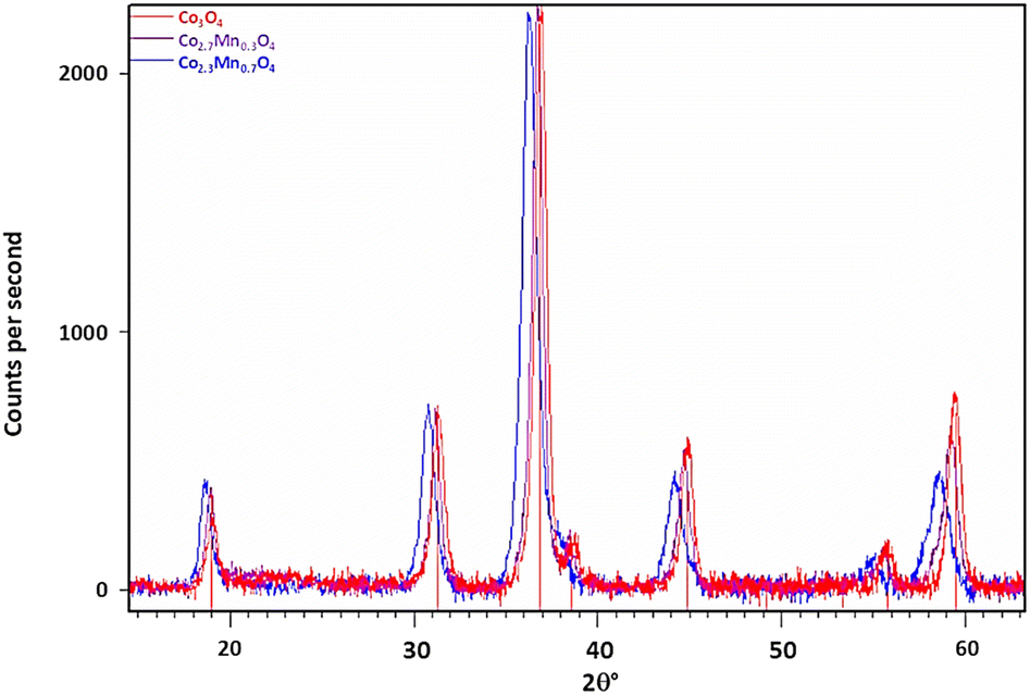 | ||
| Fig. 1 Background subtracted diffraction patterns of Co3O4 and mixed oxide samples Co2.7Mn0.3O4 (1 wt% Mn) and Co2.3Mn0.7O4 (3 % wt% Mn) with indexing lines for Co3O4 reflections at the bottom. Note the shift of Bragg reflections to lower 2θ angles with increasing [Mn]. | ||
Fig. 1 also shows the diffraction data collected from two of the Co–Mn co-injected or mixed oxide samples. The diffractogram confirms the presence of the spinel oxide phase only. If the larger Mn ion is incorporated into the spinel structure as previously suggested, then the expected response is an increase in the average lattice parameter with increasing Mn loading.19 This is confirmed from the diffraction data as a shift in peak positions to lower 2θ° values with increasing Mn doping relative to the Co3O4 reference. This is consistent with an expectation for a lattice expansion as the manganese dopant is introduced to the structure of the base Co3O4 particles.
The diffractograms for the mixed-oxide series of particles were Rietveld refined, with the resulting lattice parameters and crystallite sizes for each sample listed in Table 4. As the Mn content in the reaction mixture is increased, we observe an increase in the lattice parameter of the corresponding spinel product. As no other minor phases are detected, this suggests that the Mn introduced during the synthesis is successfully incorporated into the spinel oxide structure to form a solid solution. However, it should be noted that XRD cannot detect crystals with sizes less than 3–5 nm, and so we cannot discount particles of this size with differing phases being present.
Meena et al. reported the lattice parameters for Co(3−x)Mn(x)O4 for 0.1 < x < 1, showed a roughly linear increase in lattice parameter with increasing manganese content.20 Fig. S1† demonstrates the relationship between stoichiometry, x (the Mn concentration) and lattice parameter, compared to the lattice parameters measured for the synthesised mixed-oxide particles. While an increase in lattice parameter is observed with increasing manganese content, in our samples it is less significant than the previous report would predict. This suggests the actual composition of the samples are closer to x = 0.1 and x = 0.5 rather than the intended x = 0.3 and x = 0.7, respectively and implies that not all of the manganese introduced into the reaction mixture is being fully incorporated into the spinel structure. Two possible reasons for this are: (1) incomplete oxidation of the manganese salt during synthesis, resulting in a lower Mn:Co ratio in the final product, or (2) manganese may preferentially locate toward the surface of the particles. A difference in oxidation rates between cobalt and manganese could then create a variation in the Mn:Co ratio when comparing the surface and bulk of the nanoparticles.
Fig. 2 shows the diffractograms for the surface coated Co3O4 particles. Unlike the mixed oxide particles, no shift in spinel peak positions is observed with increasing Mn loading on the particle surfaces. Additionally, no Mn3O4 or any other crystalline phases are detected. This suggests that the impregnation method used to deposit Mn onto the Co3O4 particle surface is successful in creating a well distributed surface coating without altering the core spinel structure of the nanoparticles.
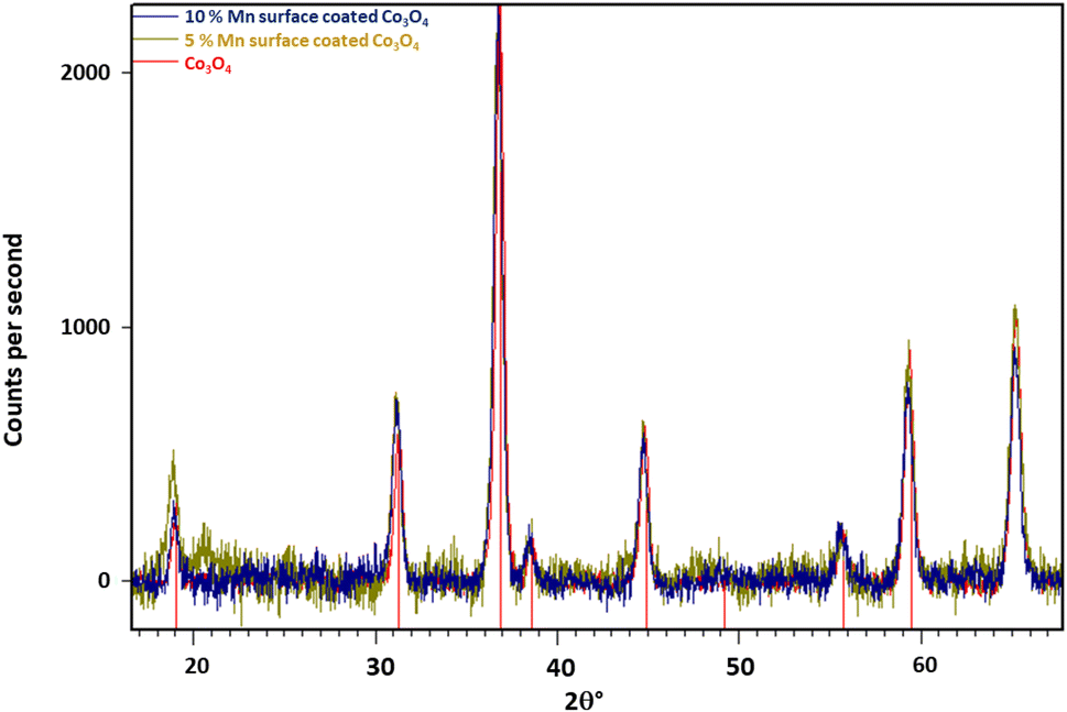 | ||
| Fig. 2 Background subtracted diffractograms of Mn surface coated Co3O4 particles, with Co3O4 reflections indexed (red). Note the weak peak at ca. 20.7° in the 5% Mn-doped sample is an artefact of the measurement process and is not ascribable to any known crystalline form of Mn or Co. | ||
Table 5 shows the Rietveld refined parameters for the Co3O4 spinel phase for a series of surface doped particles. As expected, there is only minor variability between the results, with no observable trend beyond the margin of error (∼0.001°). However, since only a small amount of surface coating was employed (up to 100:10 Co:Mn) this is not unexpected.
| Sample label | Mn (wt%) | Composition | Lattice parameter (Å) | % expansion |
|---|---|---|---|---|
| — | 0 | Co3O4 | 8.078 | — |
| 5% Mn3O4 on Co3O4 | 0.5 | Co3O4 + Mn3O4 | 8.071 | −0.09 |
| 10% Mn3O4 on Co3O4 | 1 | Co3O4 + Mn3O4 | 8.074 | −0.05 |
Table S1† shows the Rietveld refined parameters for a series of surface doped particles which have been supported on TiO2 (P25). The data confirm the retention of the Co3O4 phase, with no significant variability in the lattice parameters or the presence of other manganese phases as Mn doping increases. This lack of change suggests that manganese is effectively doped onto the surface of the Co3O4 particles, as intended, without affecting the core spinel structure or forming unwanted phases.
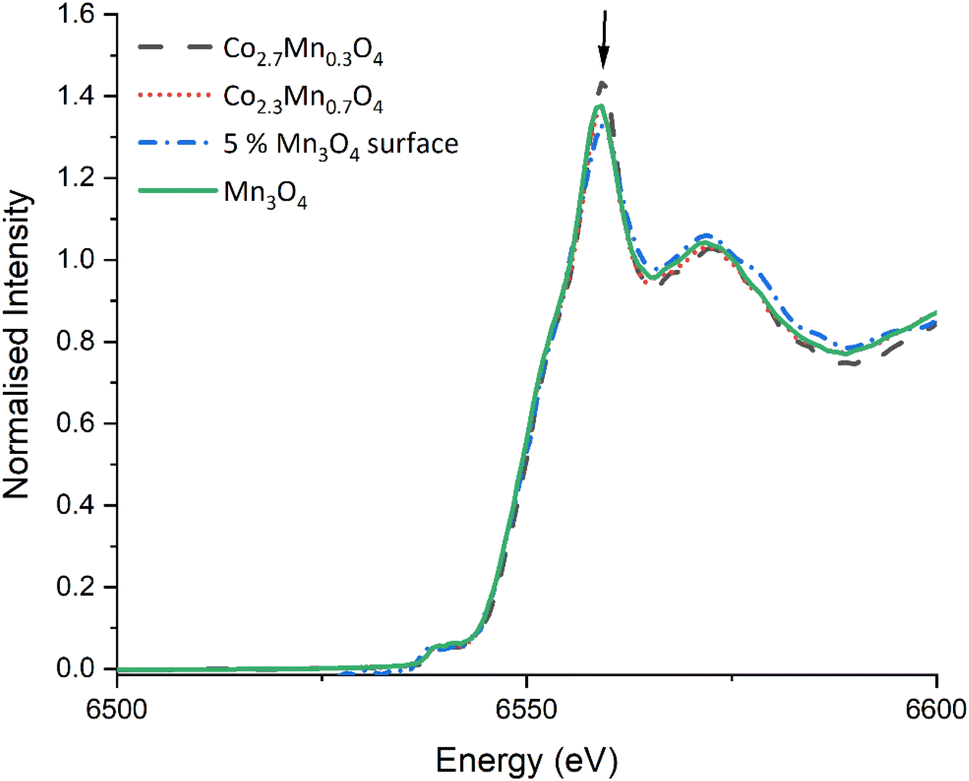 | ||
| Fig. 3 Mn K-edge XANES for TiO2 supported Co2.7Mn0.3O4 & Co2.3Mn0.7O4 mixed oxide catalysts, and 5% Mn surface doped samples and Mn3O4. Note the dilution with TiO2 renders the Mn weight% a factor ten lower in the supported catalysts than in the as synthesised oxides. The arrow at 6559 eV highlights the rising absorption edge position (1s–4p transition) where subtle changes indicate the presence of slightly different Mn species/site occupancies. | ||
![[3 with combining macron]](https://www.rsc.org/images/entities/char_0033_0304.gif) m cubic Co3O4.21
m cubic Co3O4.21
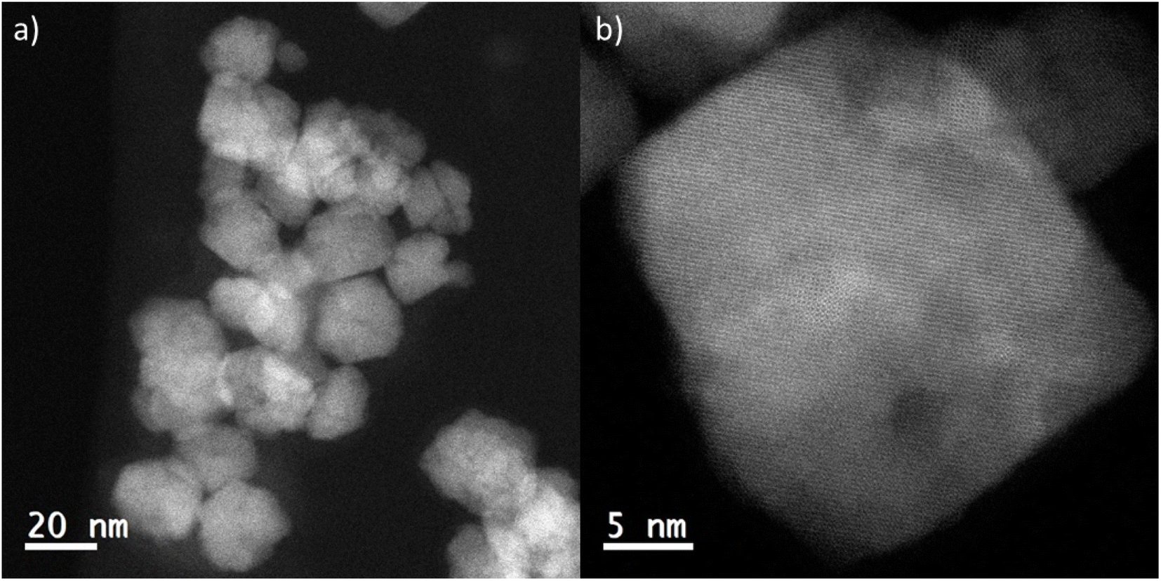 | ||
| Fig. 4 (a) HAADF STEM image of as prepared Co3O4 nanoparticles and (b) high resolution image of a single particle ∼20 nm in diameter. Note the visible lattice spacings indicates an interplanar separation of 0.288 nm, consistent with the (220) lattice spacing in spinel phase Co3O4. | ||
To understand how effectively the manganese dopant is distributed in or over the various spinel particles for each synthesis method, STEM-EDS was used to map the cobalt and manganese in the as prepared samples (Fig. S5–S7†). In the surface doped sample, the maps and accompanying linescan (acquired from arrowed region highlighted in HAADF image of the same area, Fig. 5a) illustrate an enrichment of Mn at the surface of the particles. This is consistent with XPS data (ESI, Table S2†) which confirms a surface enrichment of Mn relative to the expected synthesis and agrees with the XRD analysis indicating the core has a lower Mn content than that found by XRF. The STEM-EDS maps also show that, even at 1% Mn (100:1, x = 0.03) on Co3O4, the coverage of Mn is reasonably uniform and no hot spots are observed. This is consistent up to a surface coverage of 10% Mn on Co3O4 (Fig. S6c†) where the manganese distribution can be seen to disassociate from the cobalt distribution. The surface coating of Mn is visible as the Co elemental map shows gaps between the particles which are not visible in the Mn map. For the mixed oxide particles (Fig. 5c and S6d†) STEM-EDS shows that Co and Mn largely follow the same distribution, suggesting that the synthesis method is producing a well distributed mixed spinel oxide, which is also borne out by the XPS data which show a surface composition that matches well with the expected values and XRD measurements of the bulk composition. Surface enrichment found by STEM-EDS in these samples is much less significant and <1 nm thick.
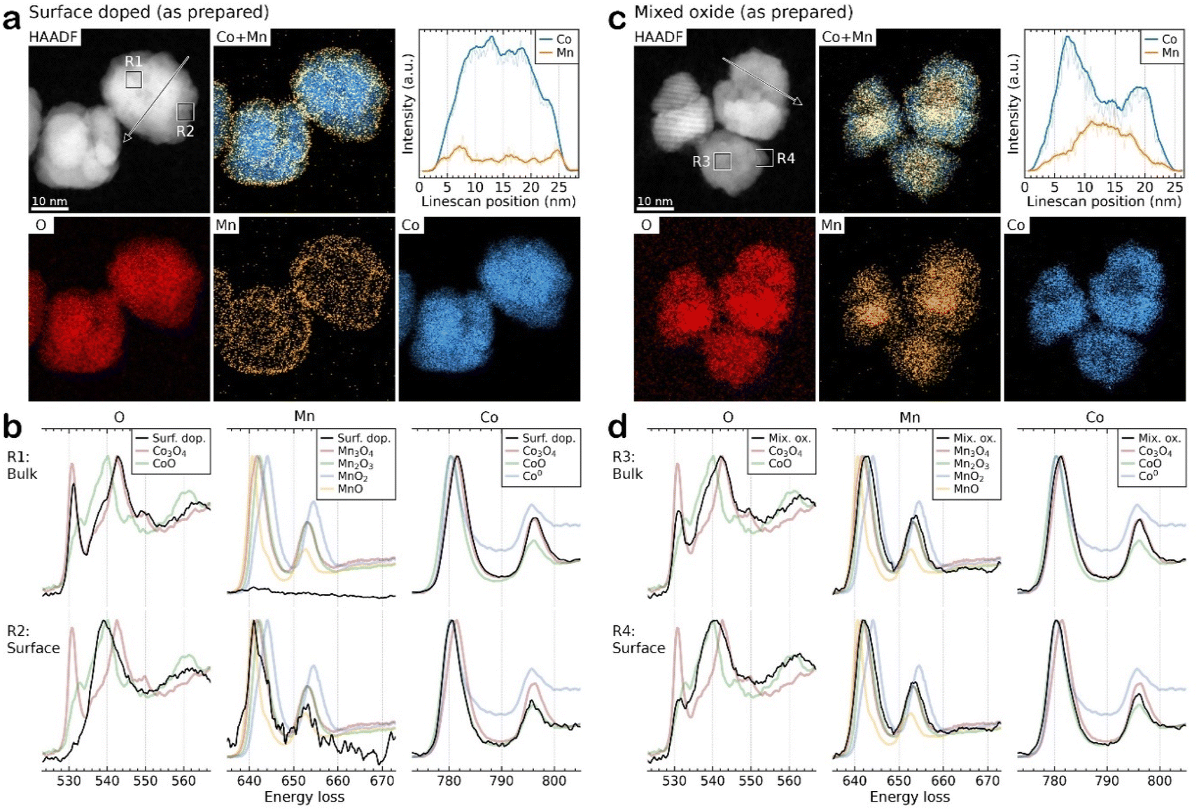 | ||
| Fig. 5 Representative HAADF imaging, EDS elemental mapping, and EELS oxidation state probing from the unsupported, as prepared (a and b) surface doped 100:30 and (c and d) mixed oxide Co2.3Mn0.7O4 samples. For the STEM-EELS in (b and d) reference spectra from various Co and Mn reference oxides and metallic species were collected for comparison. PCA deconvolution of the Co and Mn spectra was performed to identify the predominant species present. Note deconvolution of the O K-edge spectra was not performed due to overlapping contributions from Co and Mn species. | ||
STEM-EELS of the Co and Mn L2,3-edges and O K-edge were collected and compared to reference Co and Mn materials to reveal the local oxidation state of the metals in the samples. Due to the low signal-to-noise ratio (SNR) the spectra were summed over representative small local regions of interest, as highlighted by squares in the HAADF images. Fig. 5b compares the spectra acquired from the bulk (R1) and surface (R2) of the surface doped particles. The results demonstrate that virtually no Mn is present in the particle core and that the Co exists as Co3O4, whereas at the surface the Co and Mn signals match to CoO and MnO, respectively, possibly as a mixed phase. However, it should be noted that due to the low concentration of Mn the spectra has a very low SNR, making oxidation state determination difficult. For the mixed oxide Co2.3Mn0.7O4 samples, the Co is present predominantly as Co3O4 although there is some evidence of Co reduction to form CoO at the particle surfaces. Due to the close spectral similarity of Mn3O4 and Mn2O3, the Mn signal is more difficult to distinguish unambiguously into one of these specific oxide phases. Therefore, it is only possible to determine that Mn is consistent with the expected Mn3O4 (with Mn2O3 also fitting the spectral data within measurement error) and that there does not seem to be evidence of Mn reduction on the particle surfaces. In contrast for the surface doped samples (ESI Fig. S8†) the best fit is for both Mn and Co to be present in a lower oxidation state in the surface coating (as MnO and CoO), although the signal to noise ratio in these samples is lower than for the mixed oxide samples, leading to larger uncertainties in the assignment of oxidation state.
:30 and the mixed oxide catalysts to compare their structure before and after activation. Post-treatment, there is little change in the mean crystallite size, which remains as ∼20 nm, but there is an observed increase in surface segregation of Mn in both samples (Fig. S8a and c†). EELS data also confirms the surface segregation of Mn. For the surface-doped 100:30 sample, Mn is present as MnO with a CoO shell covering a metallic Co core (Fig. S8b†). In contrast, for the mixed oxide Co2.3Mn0.7O4 sample, Mn does not appear to have been reduced from Mn3O4/Mn2O3 (Fig. S8d†) and the cobalt still matches Co3O4. This suggests that either the presence of Mn as Mn3O4/Mn2O3 leads to a reoxidation of cobalt to the spinel phase during exposure to air, or that the heat treatment was not sufficient to significantly reduce the cobalt in the mixed oxide particles to its metallic phase.
In comparison, the surface coated samples do not show any lattice expansion by XRD consistent with the Mn oxide forming a highly nanocrystalline surface layer on the Co3O4 particles, rather than forming discreet Mn-oxide particles. STEM-EDS shows high dispersion of Mn over the Co3O4 particles, even at very low Mn levels (100:1 Co:Mn), with evidence of Mn present on the particle surfaces. Quantitative XPS analysis confirms a uniform Mn surface, with STEM-EELS and Mn K-edge XANES suggesting that the Mn species may contain some MnO in addition to the Mn3O4
STEM-EELS after an activation heat treatment in hydrogen reveals that in surface doped samples the Co3O4 cores are reduced to Co metal with a MnO surface layer. This observation is consistent with previous work on CoMn systems and where MnO has been identified as being present in reduced samples.17 For the mixed oxide spinel nanoparticles the Co is only partially reduced to metal in the core of the particle but the Mn remains as a spinel.
Fig. 6 shows the CO conversion measured by GC tail-gas analysis and the alcohol selectivity measured in the organic liquid products, for the two types of catalyst samples. For the surface coated samples, even the lowest Mn loading leads to a significant drop in CO conversion, which remains lower than the undoped reference throughout the series. This is not unexpected, as the manganese surface coating has the potential to cover the reduced cobalt surface and block catalytic sites from the gas phase reactants. As this series of samples was synthesised from a shared base of synthesised Co3O4 particles, any change in activity cannot be explained by an initial variation in crystallite size of the catalyst prior to or post reduction. While the lowest doping level does not appear to show a shift in % CH4 or % C5+ produced, above 0.5% Mn there is a meaningful increase in % CH4 selectivity, from 12.3 to 21%. Across the series, we can see an increase in alcohol selectivity over the reference catalyst, with selectivities ranging from 5–10% for 1% Mn and below. For the highest loaded (3%) sample however, a significant jump in alcohol selectivity to 35% is observed. Interestingly for the 3% Mn catalyst, a lower CH4 selectivity is observed compared to the rest of the series. While the lower % C5+ selectivity has not returned to the levels measured for the undoped sample, an explanation for this is the significantly reduced conversion.
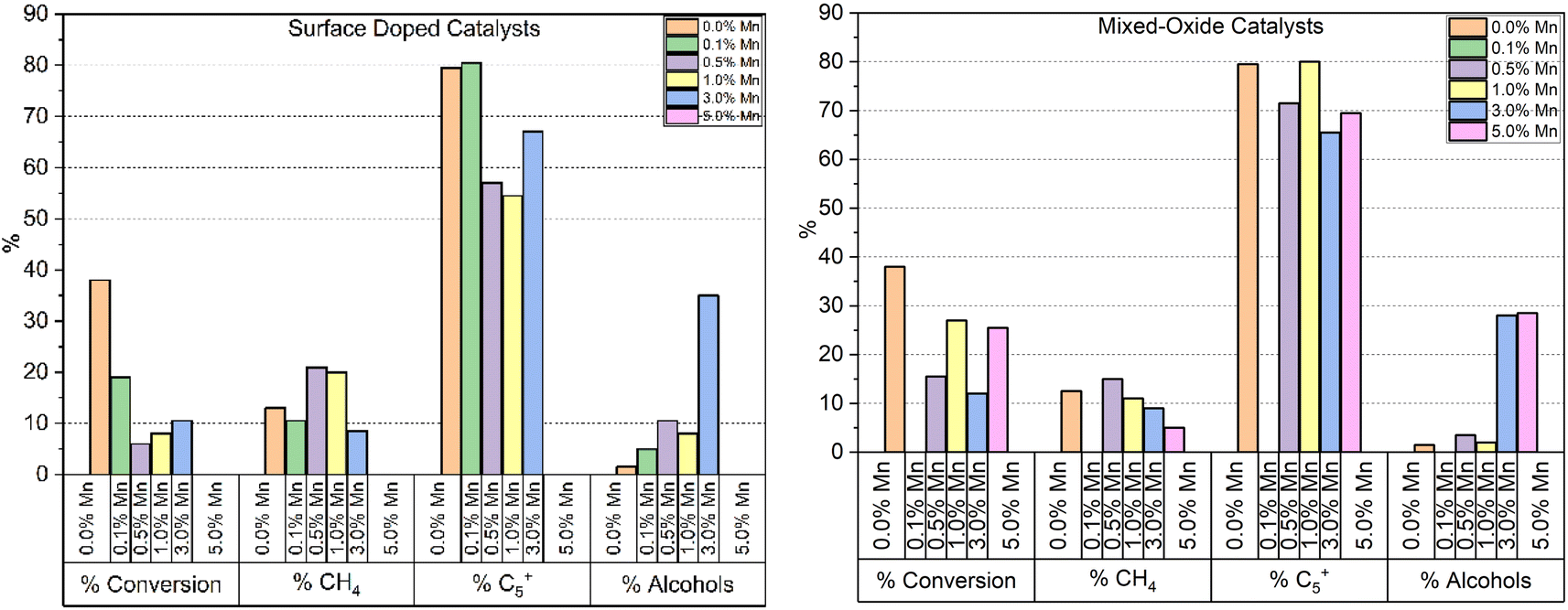 | ||
| Fig. 6 Summary of catalytic testing results of surface doped and mixed oxide catalysts at 230 °C, followed by 240 °C after ∼24 h at each temperature (i.e. total reaction time of 48 h) and 30 bar gas pressure. Note the entry on the left hand side refers to % CO converted whereas all other entries refer to particular product selectivity. | ||
The results from the testing of the mixed oxide catalyst samples are also shown in Fig. 6. As with the surface coated materials, the addition of Mn reduces the CO conversion and a significant jump in alcohol selectivity is observed at 3% Mn, which is measured at ∼30% for both the 3 and 5% Mn catalysts. However, at 1% Mn and lower the selectivity remains relatively unchanged in relation to the Co3O4 reference sample. While the mixed-oxide catalyst series does show a drop in conversion throughout compared to the un-doped catalyst, the drop is less significant than that observed by the surface coated samples, as well as being more variable. Unlike the surface doped catalyst series, the mixed-oxide series is produced from particles which were synthesised separately. The smaller crystallite size of the of the as-synthesised particles is a likely major contributing factor in the variation in activity between different loading levels (Table 4). The % CH4 selectivity is also less affected by the addition of Mn in the mixed-oxide series than the surface coated samples, although we can see a steady decrease in CH4 selectivity from 0.5 to 5% Mn, the 5% Mn catalyst achieving only 5% selectivity compared to 12.3% for the undoped catalyst at the same temperature. Again, similar to the surface doped catalyst series, we can see that at higher manganese loadings, methane selectivity is improved compared to the undoped reference, a corresponding increase in C5+ selectivity is not observed. In this case however, the conversions observed are much closer together and so the effect cannot be explained by lower activity alone.
A final set of catalysts were tested, where a mixture of separate Co3O4 and Mn3O4 particles were dispersed on to the same TiO2 support at loadings of 10% Co/1% Mn and 10% Co/3% Mn respectively. Fig. 7 shows the results of the testing of these samples. For both doping levels tested, the alcohol selectivity remains unchanged relative to the catalyst reference. The lack of alcohol selectivity in the 3% Mn sample is not consistent with the selectivity observed in the 3% Mn mixed oxide or surface doped samples. This suggests that a close interaction is required between the active cobalt and manganese dopant for the effect in alcohol selectivity to be produced. Additionally, the performance of the 3% Mn sample is significantly higher than the reference and the 1% Mn sample, in regard to CO conversion, % CH4 and % C5+ selectivity.
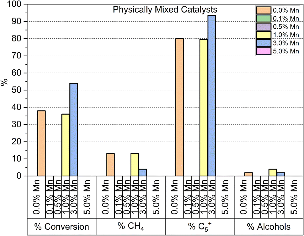 | ||
| Fig. 7 Summary of catalytic testing results of a physical mixture of Co3O4 (10%) + Mn3O4 (0, 1 and 3%) deposited on TiO2 at 230 °C, followed by 240 °C after ∼24 h at each temperature (i.e. total reaction time of 48 h) and 30 bar gas pressure. Note the entry on the left-hand side refers to % CO converted whereas all other entries refer to particular product selectivity. | ||
Paterson et al. report a significant increase in alcohol selectivity with manganese doping ≥3% on 10% Co/TiO2.10 The reported catalysts were synthesised via co-impregnation of cobalt and manganese precursor salts and characterisation shows the metals form a mixed oxide in the synthesised catalyst. For the surface coated and mixed oxide model catalysts studied, a similar increase in alcohol selectivity is observed in all catalysts with ≥3% Mn. In the mixed oxide model series, no increase in alcohol selectivity is observed below 3% Mn, whereas the surface coated series exhibits a smaller selectivity increase at 0.5 and 1 wt% loadings. The difference in behaviour between these two series implies that there is a dependence of exposed surface area of the manganese species with alcohol selectivity. This suggests the manganese phase is directly involved with the gas phase of the reaction, rather than simply imparting electronic effects onto the active cobalt metal.
The ratio of paraffins:olefins:alcohols produced by each catalyst tested is shown in Fig. 8. Overall, we can see that catalysts displaying high levels of alcohol selectivity also have higher olefin selectivity. This is consistent with the catalysts studied by Paterson et al., who report similar correlation between high alcohol selectivity and olefin selectivity.10 Meanwhile, minor increases in olefin production are observed at lower Mn doping levels without a corresponding increase in alcohol selectivity. The relationship between increased olefin production and Mn doping is expected, with Mn being reported to be effective in increasing olefin selectivity from 10 to 30% with 1% Mn doping.23
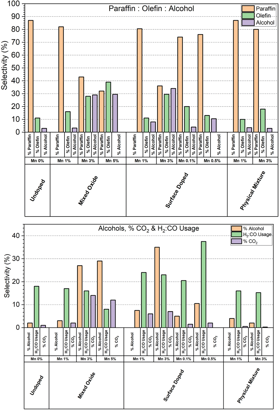 | ||
| Fig. 8 Total paraffin:olefin:alcohol selectivities for each catalyst series tested. | ||
As the range of conversions within the series of catalysts tested is wide, a more representative comparison between the samples is to look at the H2:CO consumption ratio, as shown in Fig. 8. As the WGS is also responsible for varying the H2:CO ratio, the % CO2 selectivity is also shown, however CO2 can also be formed during carbon monoxide disassociation.24 We can see a significant dependence of % CO2 selectivity in the high manganese catalysts in both the mixed oxide and surface coated series, however the % CO2 selectivity remains at the baseline for the 3% Mn physical mixtures catalyst. This suggests that it is not the manganese species itself that is responsible for the % CO2 selectivity, but rather the cobalt modified by the presence of local manganese. The catalysts that display high alcohol selectivity also display the highest % CO2 selectivity. The apparent H2:CO consumption is less consistent though, with the usage ratio swinging both lower and higher than the reference undoped catalyst.
Higher CO2 selectivity resulting from the WGS will lead to the production of H2, creating an apparent decrease in the H2:CO consumption. Previous work by some of us has shown that mixed-oxide catalysts with >3 wt% [Mn] in their formulation tend to form Co2C which has also been shown to exhibit WGS activity.11,17 As such we suspect that the high H2:CO ratios observed in catalysts with [Mn] > 3 wt% is due to the formation of increasing amounts of Co2C irrespective of the preparation method.25
 | ||
| Fig. 9 Activity of each catalyst series tested per g cobalt at 240 °C (*230 °C). Note missing data indicate where it has not been possible to extract reliable composition information from XRF. | ||
For the mixed oxide samples, each catalyst shows a significant reduction in activity in comparison to the undoped particles. Unlike the surface doped series however, the mixed oxide series do not share a consistent particle size of the spinel oxide as they were synthesised separately, so the activity results have not been deconvoluted from the effect of crystallite size, or metal surface area, on activity.
The 3% Mn catalyst in the physical mixture series is the only catalyst tested that outperforms the reference catalyst. The difference is more significant than it appears in Fig. 9, as the 3% Mn sample is operating at a temperature 10 °C lower than the rest of the catalyst series.
Fig. 10 shows the CO conversion data for the physical mixture series. As shown, the conversion of the 3% Mn catalyst increases over time at 230 °C, climbing from ∼38 to ∼55% over a span of 3 days at 230 °C. This suggests that there is a significant amount of restructuring occurring within this sample. This observation was unique to the 3% Mn physical mixture, and progressively increasing conversion was not observed in any other of the model catalyst systems discussed. The most common explanation for a steady increase in CO conversion is due to further reduction of cobalt oxide during the FT reaction, due to only partial reduction occurring during the activation procedure. This explanation appears insufficient to explain this observation however, as the Co3O4 particles supported in this catalyst are identical to those in the reference catalyst. Additionally, the 3% Mn physical mixture catalyst shows an improvement in initial conversion at 220 °C of ∼23%, compared to ∼14% in the reference Co3O4 catalyst, with this gap increasing during the lifetime of the run.
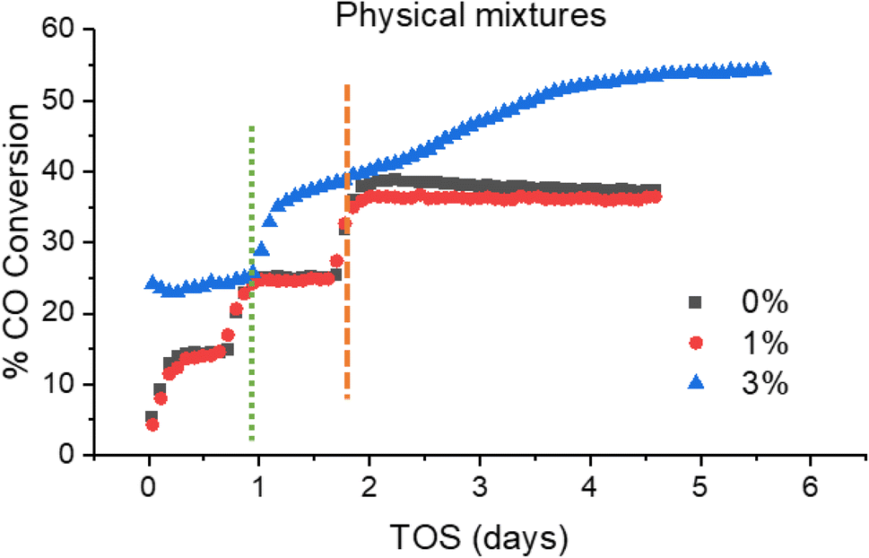 | ||
| Fig. 10 Activity profile of physical mixture model catalysts throughout testing, with temperature increases from 220–230 °C (green dotted line) for each catalyst, and temperature increase from 230–240 °C (orange dashed line) for 0 and 1% Mn catalysts only. Note Time On Stream (TOS). | ||
While the addition of separate Mn3O4 particles to the 3% physical mixture catalyst appears to have no effect on the alcohol selectivity (Fig. S9†), as well as the increased activity there is an increase in % C5+ selectivity to 93.5%, and corresponding decrease in % CH4 selectivity to 3.62%, which is remarkably low for a cobalt FT catalyst at these temperature ranges.26–28
Summary and conclusion
Despite the different synthetic methods employed Mn is, according to XRD, initially present predominantly as Mn3O4 although we note that the structural similarity of Mn2O3 renders it almost impossible to determine how much of the latter phase is present by the characterisation techniques available. HAADF-STEM/EDS/EELS measurements revealed that after a heat treatment activation step, both types of catalyst exhibited Mn surface enrichment on the Co nanoparticles; with Mn seen to exsolute in the case of the mixed oxide samples. The catalysts prepared by the two different methods and possessing Mn loadings up to 5 wt% when supported on TiO2 produced catalysts which showed similar and reproducible (from previous work) FTS performance in terms of CO conversion and particularly the selectivity to alcohols, olefins and CO2. The mixed oxide catalysts did exhibit some variance in CO conversion which can be rationalised in terms of crystallite size variation for the original synthesised material. This suggests that the delivery of Mn does not particularly affect the FTS performance considering the (mixed) oxide synthesis method could be optimised further to eliminate this variable. It also suggests that the state of Mn after reduction (predominantly MnO for the surface doped and Mn3O4/Mn2O3 for the mixed oxide samples respectively) does not affect catalytic performance since it is likely that MnO is present in both samples when they are operating at elevated pressures in a syngas mixture. As for the state of Co, it has previously been reported that the presence of increasing Mn leads to the formation of Co2C. Since the catalyst could not be recovered after testing it was not possible to confirm whether this phase had formed although we note the higher amount of CO2 produced (greater water gas shift activity) is consistent with such a phase being present.The performance testing data for the physically mixed samples when supported on TiO2 returned a result that suggests that 1% Mn3O4 does not lead to a significant coverage of the surface of the Co as the CO conversion (and product selectivity) is only slightly reduced when compared to Co without Mn doping. A particularly interesting result however was obtained with the physical mixture containing 3% Mn3O4. Not only does the catalyst exhibit improved CO conversion, it does so without a greater selectivity to olefins, alcohols and CO2 – seemingly the physical separation leads to a synergistic effect. These results are consistent with previous research that show CO conversion increasing with [Mn] although typically when the Mn is in close proximity to the Co although in this instance it can be rationalised that the Mn and Co speciation under reaction conditions are sufficiently different and therefore alcohol & olefin formation is avoided.
When comparing the results obtained for the physically mixed samples with the surface doped and mixed oxides, it is clear that the close proximity of Co and Mn is necessary for realising catalysts with a high selectivity to oxygenates and olefins. Based on past studies this proximity seems important for the formation of Co2C although the reason and mechanism by which this happens is unclear and requires further investigation. Ultimately understanding quite how this proximity effect works in practice would require a high fidelity chemical imaging study of these catalysts under operando conditions and for several hours on stream.29
Data availability
Processed data (spectra and patterns) are available from the following repository: https://rdr.ucl.ac.uk/.Conflicts of interest
Andrew M. Beale reports a relationship with Finden Ltd that includes: equity or stocks and funding grants.Acknowledgements
Engineering and Physical Sciences Research Council (EPSRC) and BP are acknowledged for an iCASE award for JP and DF. The UK Catalysis Hub are thanked for access to XAFS beamtime through the B18 BAG. The ISIS Characterisation Laboratory are acknowledged for access and use of the powder diffractometer. We also acknowledge access to EPSIC beamtime via proposal MG22431. S. J. H. and M. L. acknowledge funding from BP through the BP-International Centre for Advanced Materials (ICAM53 project) and from the EPSRC for funding under grants EP/M010619/1 and EP/P009050/1, and the European Research Council (ERC) under the European Union's Horizon 2020 research and innovation programme (Grant ERC-2016-STG-EvoluTEM-715502). TEM access was supported by the Henry Royce Institute for Advanced Materials, funded through EPSRC grants EP/R00661X/1, EP/S019367/1, EP/P025021/1 and EP/P025498/1. X-ray photoelectron (XPS) data were acquired at the EPSRC National Facility for XPS (“HarwellXPS”, EP/Y023587/1, EP/Y023609/1, EP/Y023536/1, EP/Y023552/1 and EP/Y023544/1).References
- F. Fischer and H. Tropsch, Ber. Dtsch. Chem. Ges. (A and B Series), 1923, 56, 2428–2443 CrossRef.
- A. N. Stranges, in Studies in Surface Science and Catalysis, ed. B. H. Davis and M. L. Occelli, Elsevier, 2007, vol. 163, pp. 1–27 Search PubMed.
- F. Morales, F. M. F. de Groot, O. L. J. Gijzeman, A. Mens, O. Stephan and B. M. Weckhuysen, J. Catal., 2005, 230, 301–308 CrossRef CAS.
- F. Morales, D. Grandjean, A. Mens, F. M. F. de Groot and B. M. Weckhuysen, J. Phys. Chem. B, 2006, 110, 8626–8639 CrossRef CAS PubMed.
- H. Chen, Z. Lian, X. Zhao, J. Wan, P. F. Pieters, J. Oliver-Meseguer, J. Yang, E. Pach, S. Carenco, L. Treps, N. Liakakos, Y. Shan, V. Altoe, E. Wong, Z. Zhuo, F. Yang, J. Su, J. Guo, M. Blum, S. H. Lapidus, A. Hunt, I. Waluyo, H. Ogasawara, H. Zheng, P. Yang, A. T. Bell, N. López and M. Salmeron, Nat. Commun., 2024, 15, 10294 CrossRef CAS PubMed.
- C. L. Tucker, Y. Ragoo, S. Mathe, L. Macheli, A. Bordoloi, T. C. R. Rocha, S. Govender, P. J. Kooyman and E. van Steen, J. Catal., 2022, 411, 97–108 CrossRef CAS.
- M. Lindley, P. Stishenko, J. W. M. Crawley, F. Tinkamanyire, M. Smith, J. Paterson, M. Peacock, Z. Xu, C. Hardacre, A. S. Walton, A. J. Logsdail and S. J. Haigh, ACS Catal., 2024, 14, 10648–10657 CrossRef CAS PubMed.
- S. E. Colley, R. G. Copperthwaite, G. J. Hutchings, S. P. Terblanche and M. M. Thackeray, Nature, 1989, 339, 129–130 CrossRef CAS.
- G. J. Hutchings, R. G. Copperthwaite and M. van der Riet, Top. Catal., 1995, 2, 163–172 CrossRef.
- J. Paterson, M. Peacock, R. Purves, R. Partington, K. Sullivan, G. Sunley and J. Wilson, ChemCatChem, 2018, 10, 5154–5163 CrossRef CAS.
- D. Farooq, M. E. Potter, S. Stockenhuber, J. Pritchard, A. Vamvakeros, S. W. T. Price, J. Drnec, B. Ruchte, J. Paterson, M. Peacock and A. M. Beale, ACS Catal., 2024, 14, 12269–12281 CrossRef CAS PubMed.
- G. Prieto, A. Martínez, P. Concepción and R. Moreno-Tost, J. Catal., 2009, 266, 129–144 CrossRef CAS.
- J. Pritchard, L. Morris, D. Walsh, S. Sadasivan, H. Ménard, R. M. Bellabarba, M. T. Weller and R. P. Tooze, Catal. Lett., 2018, 148, 235–245 CrossRef CAS.
- Ø. Borg, S. Eri, E. A. Blekkan, S. Storsæter, H. Wigum, E. Rytter and A. Holmen, J. Catal., 2007, 248, 89–100 CrossRef.
- A. Coelho, J. Appl. Crystallogr., 2018, 51, 210–218 CrossRef CAS.
- B. Ravel and M. Newville, J. Synchrotron Radiat., 2005, 12, 537–541 CrossRef CAS PubMed.
- J. Paterson, R. Partington, M. Peacock, K. Sullivan, J. Wilson and Z. Xu, Eur. J. Inorg. Chem., 2020, 2020, 2312–2324 CrossRef CAS.
- S. B. Hendricks and W. H. Albrecht, Berichte der deutschen chemischen Gesellschaft (A and B Series), 1928, 61, 2153–2161 CrossRef.
- R. Shannon, Acta Crystallogr., Sect. A, 1976, 32, 751–767 CrossRef.
- P. L. Meena, K. Sreenivas and R. Kumar, Indian J. Pure Appl. Phys., 2015, 52, 625–631 Search PubMed.
- X. Liu and C. T. Prewitt, Phys. Chem. Miner., 1990, 17, 168–172 CrossRef CAS.
- A. Y. Khodakov, W. Chu and P. Fongarland, Chem. Rev., 2007, 107, 1692–1744 CrossRef CAS PubMed.
- G. C. Allen, S. J. Harris, J. A. Jutson and J. M. Dyke, Appl. Surf. Sci., 1989, 37, 111–134 CrossRef CAS.
- A. Tuxen, S. Carenco, M. Chintapalli, C.-H. Chuang, C. Escudero, E. Pach, P. Jiang, F. Borondics, B. Beberwyck, A. P. Alivisatos, G. Thornton, W.-F. Pong, J. Guo, R. Perez, F. Besenbacher and M. Salmeron, J. Am. Chem. Soc., 2013, 135, 2273–2278 CrossRef CAS PubMed.
- M. K. Gnanamani, G. Jacobs, W. D. Shafer, D. E. Sparks, S. Hopps, G. A. Thomas and B. H. Davis, Top. Catal., 2014, 57, 612–618 CrossRef CAS.
- R. M. de Deugd, F. Kapteijn and J. A. Moulijn, Top. Catal., 2003, 26, 29–39 CrossRef CAS.
- J. Yang, W. Ma, D. Chen, A. Holmen and B. H. Davis, Appl. Catal., A, 2014, 470, 250–260 CrossRef CAS.
- Z. Liu, G. Jia, C. Zhao and Y. Xing, Fuel, 2021, 288, 119572 CrossRef CAS.
- I. K. van Ravenhorst, C. Vogt, H. Oosterbeek, K. W. Bossers, J. G. Moya-Cancino, A. P. van Bavel, A. M. J. van der Eerden, D. Vine, F. M. F. de Groot, F. Meirer and B. M. Weckhuysen, Angew. Chem., Int. Ed., 2018, 57, 11957–11962 CrossRef CAS PubMed.
Footnote |
| † Electronic supplementary information (ESI) available. See DOI: https://doi.org/10.1039/d4su00746h |
| This journal is © The Royal Society of Chemistry 2025 |