
 Open Access Article
 This Open Access Article is licensed under a
 Creative Commons Attribution 3.0 Unported Licence
Integrated design of multifunctional reinforced bioplastics (MReB) to synergistically enhance strength, degradability, and functionality†
Jinghao
Li
a,
Wei
Liu
bc,
Alex
Chang
bc,
Zachariah
Foudeh
bc,
Jiali
Yu
bc,
Peiran
Wei
d,
Kainan
Chen
bc,
Cheng
Hu
bc,
Dhatt
Puneet
 a,
Susie Y.
Dai
*bc and
Joshua S.
Yuan
*a
a,
Susie Y.
Dai
*bc and
Joshua S.
Yuan
*a
aDepartment of Energy, Environmental, and Chemical Engineering, Washington University in St Louis, Saint Louis, MO 63130, USA. E-mail: joshua.yuan@wustl.edu
bDepartment of Plant Pathology and Microbiology, Texas A&M University, College Station, TX 77843, USA. E-mail: sydai@tamu.edu
cSynthetic and Systems Biology Innovation Hub, Texas A&M University, College Station, TX 77843, USA
dSoftMatter Facility, Texas A&M University, College Station, TX 77843, USA
First published on 14th April 2025
Abstract
Bioplastics have emerged as a tangible solution to the plastic waste crisis. However, current bioplastics like polyhydroxybutrate (PHB) are notorious for their brittle properties, poor durability, limited functionality, and relatively slow biodegradation, all of which prevent broader applications to fulfill their environmental benefits. We have hereby addressed all aforementioned challenges synergistically by designing Multifunctional Reinforced Bioplastics (MReB). Computational modeling has guided the MReB design to take advantage of the complementary properties of PHB and cellulose nanofibrils (CNF) via cross-linking the two biopolymers with toluene-2,4-diisocyanate (TDI). The MReB design significantly improved the mechanical properties of bioplastics, enabled multi-functionality, and enhanced biodegradability. Both the crystallinity and thermal stability of the films were enhanced in the MReB design. The highest tensile strength of 21.5 MPa with a Young's modulus of 4.63 GPa was achieved in MReB. MReB films also achieved substantially improved water stability, printability, and air impermeability, all of which have promoted broad applications of MReB. Furthermore, MReB showed faster degradation as compared to PHB and nanocellulose films alone and degraded as larger pieces, and avoided forming micro-pieces leading to microplastics. Metagenomic analysis revealed that the recruitment of cellulose-degrading microorganisms might have accounted for the improved PHB degradation in the composite. The MReB materials thus represented a transformative advancement in biopolymer-based plastic products, enabling drastically enhanced multifaceted performance for broader applications while mitigating environmental impact. The new mechanisms could guide the future development of composites with enhanced mechanical and biodegradable properties.
1. Introduction
Petrochemical plastic waste imposes a major environmental challenge due to low recycling rates (∼15%), high annual production (>350 million tons), and high environmental persistence. Renewable, recyclable, or biodegradable plastics could overcome these challenges via replacement of chemical plastic products with more sustainable ones.1–4 In particular, bioplastics could minimize end-life processing, be amenable for current logistics and infrastructure, and eliminate plastic pollution efficiently due to their biodegradability.5–7 Among different bioplastics, polyhydroxyalkanoates (PHA) and poly3-hydroxybutyrate (PHB) have unique advantages in this regard due to diverse chemical structures and capacity to use waste and even CO2 as feedstock for production.8–11 Despite the potential, the replacement of petrochemical plastics with bioplastics is significantly limited by the poor mechanical properties, low biodegradability, and limited functionality. First, PHA plastics were known for their poor mechanical properties. Such a limitation is particularly critical for PHB, the most abundant type of polymer in the PHA family. PHB-based plastics are brittle as compared to many other plastics used in packaging and other applications.12 For example, polypropylene (PP) is a type of common plastic film used in food packaging, with an elastic modulus of approximately 2 GPa and tensile strength up to 30 MPa.13 Most of the PHB-based plastics without modifications render an elastic modulus around 1 GPa and tensile strength below 10 MPa. PHB tensile strength and elastic modulus are significantly lower than those of polyvinyl chloride (PVC), polyethylene terephthalate (PET), polystyrene (PS), and various kinds of polyethylene (PE).14 Second, even though the biodegradability of PHB and PHA is better than that of other bioplastics like poly-lactic acid (PLA),15 the biodegradation still takes over six months and could form microplastics during degradation, while brittle plastics decompose into small pieces.16 Third, the functionality of bioplastic products needs to take into consideration industrial needs. The packaging, food, and catering industries consume nearly half of the plastic products.17 Bioplastic materials need to be water-proof, air-impermeable, and printable to fulfill the needs of the packaging industry.18 Innovative designs of bioplastic composites need to take into consideration these multifaceted challenges.Various fiber products like wood fiber have been used to reinforce PHB.19 Even though the composite improved the mechanical properties, these materials are often rigid and have limited utilization in packaging.20 The multi-functionality and improved biodegradability were not achieved in the PHB-based packaging material design, either. The new material design has to take into consideration all the three aforementioned challenges: mechanical strength, biodegradability, and multi-functionality. Both plastic material component selection and structural design are critical in achieving the synergistic improvement of all three types of properties.
In this article, we first carried out computational modeling to evaluate how various biopolymers could improve the properties of bioplastics. Cellulose materials as blends have been explored for material reinforcement to improve the short-term mechanical properties.21–23 Compared with unprocessed cellulose fibers, cellulose nanofibers (CNF) have higher crystallinity, thermal stability, and aspect ratio.24–26 The CNF from lignocellulosic biomass could serve as a sustainable reinforcement to substantially improve bioplastic mechanical properties due to the formation of network-like structures within the biopolymer matrix.27 Nevertheless, the hydrophobic PHB polymer matrix is not compatible with the hydrophilic nanocellulose filler, which makes it challenging to apply the commonly used blending and compression molding for composite fabrication.28–31 We further evaluated the blending with chemical modification versus multi-layer film design. The results have guided the design of Multifunctional Reinforced Bioplastics (MReB) to substantially improve the mechanical performance, achieve multi-functionality, and promote biodegradable capacity simultaneously. The synergistic functional design empowers MReB to be broadly applicable in packaging industries in a way that regular bioplastics cannot. MReB thus could well address the environmental challenges caused by petrochemical plastics with a broad impact on environmental sustainability (Fig. 1).
 | ||
| Fig. 1 Fabrication of MReB by integrating hydrogen bonding and TDI crosslinking, and fundamental mechanisms for the biodegradation of these bio-compostable products. | ||
2. Materials and methods
2.1. Materials
The cellulose nanofiber (CNF) slurry (fiber content 3.4%) was prepared from mechanically refined bleached softwood kraft pulp without chemical modification (the University of Maine Process Development Center).32 Toluene diisocyanate (TDI) was purchased from TCI America. Polyhydroxybutrate was purchased from Goodfellow with a molecular weight of 550![[thin space (1/6-em)]](https://www.rsc.org/images/entities/char_2009.gif) 000 g mol−1. The solvent dichloromethane was purchased from Alfa Aesar.
000 g mol−1. The solvent dichloromethane was purchased from Alfa Aesar.
2.2. Fabrication of the CNF film
Charged CNF slurry was diluted with deionized water (DI) water to form a suspension consisting of a solid content of 0.5 wt%. The CNF suspension was placed in an aluminum pan with a cover for natural drying, and then a CNF film was obtained by natural water evaporation at an ambient temperature. The obtained nanocellulose film was placed in an oven and heated to 80 °C for two hours to obtain the target film.2.3. Fabrication of PHB films with or without isocyanates
Toluene diisocyanate (TDI) was used to crosslink PHB in the composite film fabrication. PHB was dissolved in dichloromethane to form a clear solution. TDI solution (1 wt% of PHB) was added to the solution. Then, the mixture was placed in a glass pan with a cover and the solvent was evaporated naturally to form a composite film. The film was heated to 80 °C for four hours to complete the crosslinking. For the PHB film without isocyanates, the same process was applied, without adding the 1 wt% TDI solution, as a comparison sample in this study.2.4. Fabrication of MReB
The PHB/CNF and PHB/CNF/TDI (MReB) composite films were made by spraying the heated PHB suspension onto the surface of the prepared CNF film, either without or with a coating of TDI solution (1 wt% of PHB). The application of the TDI coating substantially enhanced the bonding strength between the CNF and PHB layers by creating a more effective crosslinked interface. Rather than mixing TDI with the components, spraying the TDI coating onto the surface of the CNF prior to bonding with the PHB layer prevents the formation of unwanted crosslinked networks within the CNF or PHB layers themselves. The self-bonding of CNF or PHB will cause delamination, preventing the formation of an integrated multi-layer film. The spraying and bonding approach not only improves the overall mechanical properties of the composite but also ensures a more uniform and reliable bonding between the layers, thereby enhancing the performance of the final MReB composite film. To ensure complete solvent evaporation from the PHB-based composite, the obtained film was heated to 80 °C for four hours. After heating, all samples were stored in the desiccator for further testing and evaluation. To ensure the safe use of TDI by fully reacting it with the CNF and PHB components, gas chromatography/mass spectrometry (GCMS) was used to test the TDI residue in the film.2.5. Characterization
The surface morphologies of the obtained samples were examined using a GMH focused ion beam microscope (LYRA-3 Model) with an acceleration voltage of 10 kV. The samples were gold-sputtered before SEM images.AFM analysis of CNF and PHB/CNF/TDI (MReB) films was performed using a Bruker Dimension Icon atomic force microscope (AFM).
Fourier transform infrared (FT-IR) spectra of samples were collected using KBr pellets on a Nicolet i50 FTIR spectrometer in the scan range of 4000–400 cm−1 of 32 scans with a resolution of 4 cm−1.
Thermogravimetric analysis (TGA) and derivative thermogravimetric (DTG) analysis were performed using a PerkinElmer STA600 simultaneous thermal analyzer to evaluate thermal degradation of the original and sulfonated sample in the range of 40–600 °C at a rate of 10 °C min−1 under a nitrogen flow rate of 20 ml min−1.
The storage modulus curves of CNF, PHB/CNF and PHB/CNF/TDI (MReB) composites from 40 °C to 150 °C were obtained by dynamic mechanical analysis (DMA) of TA Instruments Q850 with a heating rate of 20 °C min−1 at a constant frequency of 1Hz.
The mechanical properties were measured using a universal mechanical tester (TestResources Inc., Shakopee, MN). The measurements were performed in the uniaxial tensile mode. The samples were cut using a shape cutter according to ASTM D638 type V. The resulting mechanical properties represent the tensile properties of the films made of CNF, CNF/PHB, and CNF/PHB/TDI, respectively. Each sample was tested three times, and the averaged results with standard deviations were reported.
The X-ray diffraction (XRD) patterns of the CNF, PHB/CNF, and PHB/CNF/TDI (MReB) composite samples were analyzed using a Bruker D8 Discovery diffractometer. The instrument is equipped with a Cu Kα radiation source (λ = 0.154 nm) with a 2θ range of 10–45° and the operation voltage and current were maintained at 40 kV and 40 mA, respectively.
The crystallinity index (C.I.) of nanocellulose based on the XRD pattern was determined as33 in eqn (1):
 | (1) |
The chemical compositions of the CNF and PHB/CNF/TDI films were examined based on X-ray photoelectron spectroscopy (XPS) spectra developed using Omicron ESCA+ with a Mg X-ray source at an emission current of 20 mA and a voltage of 15 kV.
The calorimetry analysis (DSC) of PHB composites was conducted using a TA Q2500 system (TA Instruments, New Castle, DE). The samples were heated from room temperature to 250 °C at a heating rate of 10 °C min−1. The PHB crystallinity degree was calculated using eqn (2):
 | (2) |
 is the melting heat of pure crystalline PHB (assumed to be 146 J g−1),34,35 and wPHB is the weight fraction of PHB in the composites.
An HP Color LaserJet Pro M545Dn was used to print the composite film samples for the printability analysis. The A4 side lab handmade CNF, CNF/PHB, and PHB/CNF/TDI (MReB) films were used to print the university logo. MATLAB binary graph function was employed to analyze the effective printable area from the images taken using a Swift SW380t optical microscope and Swift imaging 3.0 software.
The water stability tests were conducted in DI water for all the CNF, PHB/CNF, and PHB/CNF/TDI (MReB) composite films. The films were soaked in the water for 24 hours, and then the surface water was naturally dried before the tensile test. After that, the samples were used to prepare specimens for the tensile test according to the ASTM D638 standard. Five replicates of each sample were obtained for the tensile test and then the standard derivation was calculated. In addition, the CNF and PHB/CNF/TDI (MReB) films were used to make straws by hand for the water stability test shown in the demo video. The weight gain percentages of the CNF and PHB/CNF/TDI (MReB) straws are reported in the ESI.† The average values and standard derivations were calculated from three replicates.
The oxygen transmission rates (OTR) of CNF, PHB/CNF, and PHB/CNF/TDI films were determined at 23 °C and 0%RH, using the Illinois Instrument Model 8001 based on the ASTM d3985 standard. The standard test area was 100 cm2 with ultra-pure oxygen. The OTR results were reported in milliliters per square meter per day. To convert the ORT to Oxygen permeability and permeability coefficient, the thickness of the film and partial pressure difference were measured. The thickness of the film and partial pressure difference were measured. Each sample has four specimens for the test to minimize the error. The results are reported in Tables S1 and S2,† and Fig. 4(c).
To verify that our material manufacturing process has removed all TDI residues, we have carried out the GC/MS analysis of MReB. The MReB samples were immersed in a hexane solution for 4 hours and then analyzed by GC/MS. The resulting spectra were identified through the built-in database and compared with a standard curve prepared from TDI hexane solutions of varying concentrations.
2.6. Biodegradation test
The biodegradation test was conducted in the greenhouse of Plant Pathology and Microbiology at Texas A&M University in College Station, Texas. The soil was topsoil from Earthgro. Four identical pieces of each original PHB, original CNF, TDI crosslinked PHB, PHB/CNF with or without TDI crosslinking square, control polypropylene (PP), and control PE (polyethylene) samples with a width of 300mm and thickness around 1mm were prepared. Each sample was weighed before being placed in a non-degradable PP mesh bag for easy retrieval. The samples were then buried in the soil approximately 20cm below the surface in a garden plastic tray container. The tray was divided into eight blocks, each block representing a group of samples. The greenhouse was climate controlled at 28 °C with 65% humidity. The internal soil temperature 20cm below the soil surface was approximately 23 °C and was irrigated uniformly with 1 L m−3 or deionized water twice per week. All samples were taken out to measure the biodegradation rate every seven days for up to eight weeks. Before measurement, the surfaces of the samples were cleaned using a brush and then dried by clamping samples between VWR tissue papers for five hours until reaching equilibrium. The tissue papers were changed once becoming wet during this conditioning process. All of these processes were performed in a climate-controlled room, and four replicates for each group were measured to minimize variation. The percentage weight loss of samples after each degradation time interval was calculated from the following eqn (3):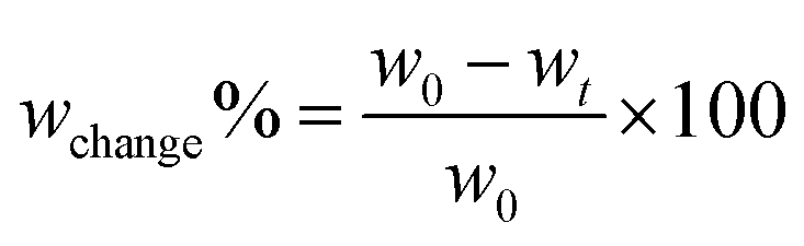 | (3) |
2.7. Microbial community identification
Degraded materials from the biodegradation test were collected at week 16 after being buried under five conditions: original PHB, original CNF, TDI crosslinked PHB (PHB/TDI), and PHB/CNF with or without TDI crosslinking square (PHB/CNF and PHB/TDI/CNF). Up to 200 mg of soil or degraded materials were subjected to genomic DNA extraction with DNeasy PowerSoil Pro Kit (Qiagen, MD, USA) following the manufacturer's instructions. Genomic DNA was sent to Novogene (Novogene Inc. CA, USA) to perform ribosomal RNA 16S amplicon sequencing for bacterial profiling and ribosomal internal transcribed spacer (ITS) amplicon sequencing for the fungal community profiling. The bacterial community was sequenced by NovaSeq 250 bp paired-end sequencing targeting the V3–V4 region, while the fungal community was sequenced using the same platform targeting ITS1-5F for general fungal identification. Approximately 0.5 million raw reads were obtained for each sample, and both 16S and ITS1 sequencing reads were analyzed using QIIME2 version 20201.11.0 with default settings.36 Cleaned reads were analyzed under the processes of quality control, DADA237 denoising, and taxonomy assignment against the reference databases. Bacterial taxonomy was identified using a pre-trained classifier SILVA-138 at the 99% similarity. Fungal taxonomy was assigned with the Naive Bayes classifier trained classification against the UNITE database (QIIME release 10.05.2021).38 Unannotated taxa and sequences were removed from the UNITE database to reduce noise and improve classification accuracy. The relative abundance of bacterial and fungal taxonomic profiles was obtained and visualized with the R package ‘ggplot2’.39 A total of 9127418 raw reads were obtained from the paired-end Illumina sequencing platform, targeting the bacterial 16S rRNA V3–V4 region or the fungal ITS1 region. Approximately 400000 reads per sample were retained after filtering and denoising processes. For bacterial sequences, 1094301 filtered reads were clustered into 6589 operational taxonomic units (OTUs) with the threshold of 97% sequence similarity. 1600610 fungal reads were clustered into 1924 OTUs with the same threshold. Taxonomies were identified and assigned to OTUs with a confidence score greater than 70% as the cutoff standard.
The 16S sequencing and ITS sequencing data were deposited to NCBI SRA under BioProject PRJNA800810. Supporting scripts and detailed analysis pipeline commands are available on the GitHub repository (https://github.com/joshuayuanlab151/PHB-metagenomics).
3. Results and discussion
3.1. Model-guided design of MReB (multifunctional reinforced bioplastics)
To design strong, biodegradable, and multifunctional bioplastics for broader applications, we first screened a wide range of biopolymers for PHB reinforcement through computational modeling (ESI Note 1†). As shown in Fig. S1a,† the models suggest that the particle-like reinforcement, such as lignin or starch, has a limited impact on the strength of the plastic composite as compared to the fibers like cellulose (ESI eqn (S1) and (S2)†). The high modulus of cellulose fiber could significantly enhance the modulus of the plastic composite, following the hybrid mixture and the laminate analogy approach, as verified by the model (eqn (S2)) in Fig. S1b.†Cellulose is the most abundant biopolymer on Earth, and its properties, such as the fiber diameter, molecular structure, functional groups, and crystalline alignment, could all impact its effectiveness as a reinforcement material. When the size of cellulose decreases from micro- to nano-scale, the fiber length to diameter ratio significantly increases.40–42 The processed cellulose nanofibers can achieve up to 77 GPa tensile strength and up to 220 GPa modulus.43 Such an increase in fiber mechanical properties could result in an effective improvement in the mechanical properties of the as-designed plastic composite according to the model (ESI eqn (S3)†). We therefore identified cellulose nanofibers (CNF) as an effective reinforcement to enhance PHB plastic performance. Then, we systemically evaluated the multi-functionality and biodegradability, considering that cellulose has been used for a broad range of functional materials and is a natural substrate for microorganisms.
Even though CNF could provide mechanical strength, CNF is not compatible with PHB and many other bioplastics due to its hydrophilic properties that require further modification, hindering its application as a biofiller for hydrophobic bioplastics. To address this challenge, a multi-layer design concept with an interlayer crosslinking structure was introduced to design CNF-reinforced plastic composites, as shown in Fig. S1c.† The model in ESI eqn (S4)† can well predict the modulus of the MReB (4.42 GPa), which is consistent with the experiments of 4.63 GPa with only 4.5% difference (Table S1†). Compared to the previously reported PHB/CNF blended composites, the tensile strength and modulus of the MReB exhibited significant enhancements, achieving increases of 43% and 25%, respectively.31 These improvements underscore the effectiveness of the multi-layer design method. Additionally, this design offers improved thermal stability as the CNF content in the composite increases, without being compromised by thermorheological properties or manufacturing processes. Overall, the computational and conceptual design guided the manufacturing of CNF-reinforced bioplastics with PHB as an example. Considering the complementary properties of both materials, we also examined biodegradability, air permeable resistance, printability, water stability, and durability. The multi-functionality properties are critical to the broad application of MReB as a replacement for petrochemical-based plastics.
3.2. The optimal reinforcement of MReB overcame the mechanical performance limitation
The neat PHB is a brittle material. The PHB film from our study has a poor ultimate tensile strength at 5.31 MPa and a low Young's modulus at 1.36 GPa, as shown in Table 1. The poor mechanical properties highlighted that PHB alone could not produce quality products to replace petrochemical plastics.44 Although the aforementioned modeling indicated that CNF could reinforce PHB, the incompatibility of hydrophilic CNF and hydrophobic PHB could lead to premature debonding, preventing the composite design. We therefore explored TDI to covalently crosslink the CNF fibers and PHB polymeric chains to form the multi-layer film design instead of polymer blends (Fig. 2(a)). Eqn (S4)† also indicates that such a design could lead to materials with high mechanical properties. The design will integrate hydrogen bonding and crosslinking to prevent premature debonding. The resultant MReB has shown superior mechanical performances, as shown in Fig. 2(b), and (c). The typical stress–strain curves for the MReB with various designs including the PHB content and TDI crosslinker are shown in Fig. 2(b) and (c). The ultimate tensile strength and modulus are summarized in Table 1. The results highlighted that the tensile strength doubled and Young's modulus increased by about 130% through CNF reinforcement when using TDI to crosslink. | ||
| Fig. 2 (a) Schematic diagram of the MReB fabrication process. (b) Stress–strain curves of the prepared PHB and CNF with different ratios. (c). Stress–strain curves of the prepared films with different combinations. (d) Thermogravimetric analysis (TGA) curves and (e) derivative thermogravimetric (DTG) curves of films with different combinations. (f) DSC curves of films with different combinations. (g) and (h) are top-view and cross-sectional view SEM images of PHB/CNF; (i) and (j) are top-view and cross-sectional view of the PHB/CNF composite using TDI as a bonding agent during fabrication. The weight ratio of PHB to CNF (dry weight) is 1:1 and the weight of TDI is 1% weight of PHB. (k) FT-IR spectra of films with different combinations. (l) XRD patterns of films with different combinations. | ||
| Samples | σ (MPa) | E (GPa) | ε (%) |
|---|---|---|---|
| Original PHB (PHB) | 5.3 ± 1.7 | 1.36 ± 0.5 | 1.72 ± 0.7 |
| Original CNF (CNF) | 44.8 ± 2.2 | 16.8 ± 0.2 | 0.85 ± 0.5 |
| TDI crosslinked PHB without CNF (PHB/TDI) | 6.5 ± 1.5 | 1.52 ± 0.2 | 1.75 ± 0.2 |
| PHB(50%)/CNF composite without TDI crosslinking (PHB/CNF) | 11.0 ± 1.3 | 2.01 ± 0.3 | 1.41 ± 0.7 |
| PHB(50%)/CNF composite with TDI crosslinking (MReB) | 21.5 ± 0.5 | 4.63 ± 0.5 | 1.19 ± 0.5 |
| PHB(60%)/CNF composite with TDI crosslinking (PHB60%/CNF/TDI) | 17.5 ± 1.5 | 2.67 ± 0.5 | 1.25 ± 0.3 |
| PHB(70%)/CNF composite with TDI crosslinking (PHB70%/CNF/TDI) | 7.3 ± 0.8 | 1.41 ± 0.4 | 1.55 ± 0.4 |
The significant reinforcement of CNF and TDI crosslinking in the PHB matrix also verified the model, in that the reinforcement actually comes from nanocellulose. When 1% weight of TDI without CNF reinforcement was added to the PHB polymer, the tensile strength only increased by 22% (to 6.5 MPa) as compared to that of the neat PHB film. However, when PHB and CNF were crosslinked by TDI, the ultimate tensile strength of the 50 wt% PHB containing MReB significantly improved to 21.5 MPa, which is a four-fold increase. The Young's modulus was also increased to 4.63 GPa, which represents a three-fold increase. With the further increase of the PHB content in the MReB film, both tensile strength and modulus decreased. Furthermore, the chemical reaction of the TDI crosslinking can be confirmed by the spectra of the XPS test (Fig. S4(a) and (c));† the new peak at 287.4 eV appeared, representing the N–C![[double bond, length as m-dash]](https://www.rsc.org/images/entities/char_e001.gif) O linkage in the C1s spectra of PHB/CNF/TDI (MReB) (Fig. S4(d)),† which was not observed in the spectra of CNF films (Fig. S4(b)).† This finding verified the design of the MReB with efficient crosslinking. Overall, the results highlighted the effectiveness of the MReB design. Both the empirical model and the design could guide the future development of reinforced biodegradable films.
O linkage in the C1s spectra of PHB/CNF/TDI (MReB) (Fig. S4(d)),† which was not observed in the spectra of CNF films (Fig. S4(b)).† This finding verified the design of the MReB with efficient crosslinking. Overall, the results highlighted the effectiveness of the MReB design. Both the empirical model and the design could guide the future development of reinforced biodegradable films.
3.3. The multilayer structure of MReB improved thermal stability
Thermal stability is an important parameter for plastic applications. Generally, higher thermal tolerance of plastic products could expand the application. We explored if the MReB design could improve thermal stability. The results of the thermogravimetric (TG) curves and derivative thermogravimetric (DTG) curves are shown in Fig. 2(d) and (e) and also summarized in Table 2. The temperature at the 5% weight loss of the total mass (T5%) is recognized as the onset temperature for thermal degradation. The CNF sample had a low onset degradation temperature of 112.6 °C yet a fairly high 50% weight loss of the total mass (T50%) at 381.4 °C due to its high hydrophilicity and moisture evaporation.| Samples | T 5% (°C) | T 50% (°C) | T max (°C) PHB phase | T max (°C) CNF phase | Char residue/% (at 600 °C) |
|---|---|---|---|---|---|
| a The temperature at a weight loss of 5%. b The temperature at a weight loss of 50%. c The temperature at the maximum decomposition rate. | |||||
| PHB | 208.4 | 307.8 | 310.3 | — | 2.97 |
| CNF | 112.6 | 381.4 | — | 383.4 | 20.0 |
| PHB/TDI | 223.9 | 310.2 | 316.2 | — | 3.64 |
| PHB/CNF | 192.3 | 321.4 | 280.0 | 387.5 | 6.88 |
| PHB/CNF/TDI (MReB) | 210.0 | 343.1 | 317.8 | 388.4 | 11.2 |
The temperatures of the original PHB at 50% weight loss of total mass (T50%) and at the maximum decomposition rate (Tmax) were 307.8 and 310.3 °C, respectively. There was only 2.97% residue char left at the temperature of 600 °C. With the crosslinking of TDI, T50% and Tmax of PHB slightly increased to 310.2 and 316.2 °C, respectively. The char residue increased as well after the TDI crosslinking. These changes could be attributed to the bonding of PHB polymer chains. The further crosslinking of PHB and CNF with TDI substantially improved the thermal stability. The T5%, T50%, and Tmax of PHB/CNF/TDI (MReB) (i.e. PHB and CNF crosslinked by TDI) all increased. In particular, the T5% of MReB was slightly higher than that of the neat PHB film. Nevertheless, the T50% and Tmax of MReB were both substantially higher than the neat PHB film and the PHB/CNF film without TDI crosslinking. More interestingly, the Tmax of MReB was even slightly higher than that of CNF alone film, although the T50% of MReB was still lower than that of CNF. The results highlighted that the MReB design overcame the low thermal stability of individual materials and achieved the synergy to systemically improve the thermal stability at all stages. Such improvement could be due to the merits of the multilayer structure associated with the formation of covalent bonding by TDI crosslinking to better integrate CNF and PHB, allowing both polymers to leverage the performance of one another, both for mechanical properties and thermal stability.
Dynamic mechanical analysis (DMA) can determine mechanical properties as a function of temperature. The storage modulus curves of CNF, PHB/CNF, and PHB/CNF/TDI (MReB) films are shown in Fig. S5.† The storage modulus of PHB-derived films is much higher than that of the CNF film across the entire temperature range, which is likely due to the dense PHB surface layers. However, the storage moduli of both PHB/CNF with and without TDI decrease as the temperature rises. This phenomenon may be attributed to the thermoplastic nature of the PHB component, in contrast to the CNF. Compared to PHB/CNF without TDI, the storage modulus of PHB/CNF with TDI crosslinking is improved, indicating that MReB has better thermal stability.
The calorimetry analysis (DSC) of PHB composites was further performed to investigate the melting behavior of PHB and MReB. As shown in Fig. 2(f) and Table 3, double-melting points of PHB were observed for all samples containing PHB, due to the recrystallization and re-melting behavior during the DSC measurement.45 The lower temperature melting peak (Tm1) stands for the melting point of the original crystals formed in the composite fabrication process, and the higher peak (Tm2) is associated with the melting process of the recrystallized crystals during the DSC scan.46Table 3 summarizes Tm1 and crystallinity (χPHB) of PHB. With the crosslinking of TDI or compositing with CNF, the melting temperature and crystallinity of PHB increased, which is consistent with the results of TGA. These results suggested the formation of a thicker layer and greater crystalline order in MReB as compared to the original PHB polymer.
| Samples | T m1 (°C) | T m2 (°C) | χ PHB (%) |
|---|---|---|---|
| PHB | 149.9 | 168.7 | 70.0 |
| PHB/TDI | 152.0 | 169.8 | 76.7 |
| PHB/CNF | 150.9 | 169.5 | 81.3 |
| PHB/CNF/TDI(MReB) | 151.4 | 169.6 | 83.4 |
3.4. MReB morphology revealed mechanisms of improved mechanical and thermal properties
In order to understand the mechanisms for improved properties in MReB design, we carried out scanning electron microscopy (SEM) analysis of the different composites. Fig. 2(g), (h), (i) and (j) show the SEM images of the PHB/CNF film without and with TDI crosslinking. As shown in Fig. 2(h), cellulose nanomaterial bundles are visible as foam-like cores on the SEM images and have a diameter in micro-sizes (nominal 10 μm). These cellulose bundles are in the middle layer of the composite. They are formed by hydrogen bonding between nano-sized fibers during the drying process, which constitutes a mesh-like framework to achieve high strength under external force.47 The forming of cellulose nano-bundles can provide strong support for the PHB polymer matrix, which is consistent with the empirical model prediction.More importantly, MReB integrated the CNF framework and PHB with effective chemical crosslinking, as shown in the cross-sectional view of the SEM image in Fig. 2(j). The MReB film has a layered structure, the middle layer (nominal 10 μm) is bonded CNF, and the PHB layers (nominal 5 μm) are on the outsides. After the chemical crosslinking by TDI between the CNF and PHB layers (Fig. 2(j)), the MReB layered structure becomes denser and has much fewer voids than the PHB/CNF composite without TDI (Fig. 2(h)), particularly in the PHB dense layers. These structural changes could have accounted for the improved mechanical properties of the MReB film.
The changes in the MReB chemical structure caused by TDI crosslinking were investigated by FT-IR, as shown in Fig. 2(k). The original PHB has a characteristic vibration at about 1720 cm−1, which can be assigned to the stretching vibration of the carbonyl group of PHB.48 The peaks in the range of 900–1500 cm−1 need more deconvolution. Generally, the bands in 900–1200 cm−1 are regarded as the contributions of the symmetric stretching vibration of C–O–C groups in PHB, while the peak around 1380 cm−1 denotes the symmetric wagging of CH3 groups.48,49 The characteristic IR bands for native CNF (red line) are the –OH stretching at 3345 cm−1, C–H symmetrical stretching at 2899 cm−1, CO stretching vibration at 1640 cm−1, and C–O–C asymmetrical stretching at 1060 cm−1.50,51 The vibration change after the TDI crosslinking is not obvious (shown as a green line), possibly because only a small amount of TDI (1 wt% of PHB) was used in the interlayers between the CNF and PHB layers. Additionally, the TDI and CNF-related peaks, such as excess –OH, could be obscured by the PHB surface due to the FTIR test, which only works on surface characterization. The spectra of PHB/CNF/TDI (MReB) were similar to that of the neat PHB (gray line), suggesting that the PHB layer was well assembled on the surface of CNF layers.
X-Ray Powder Diffraction (XRD) analysis was also conducted to analyze the crystalline structures of PHB in different samples. In the XRD patterns of PHB (Fig. 2(i)), the characteristic diffraction peaks at 2θ = 13.5° and 16.8° were assigned to the (020) and (110) planes of the orthorhombic unit cell of a PHB crystal. In addition, small peaks around 20°, 21.5°, 22.3° and 25° attributed to (021), (101), (111), and (121) plane diffractions of PHB were detected46,52 (Fig. 2(i), black line). For the CNF pattern, two crystalline peaks at 15.8° and 22.5°, assigned to the characteristic peaks of crystalline cellulose,53,54 were observed, but rather weak. The XRD pattern of the PHB/CNF composite is very similar to that of PHB, indicating that the PHB polymer remains intact in the composites. Nevertheless, the XRD signal intensity of MReB is substantially lower than that of the PHB/CNF composite. The results suggested that the TDI inter-bonding impacted PHB–CNF cross-linking to form the dense layer structure and improve functionalities.
3.5. The MReB substantially improved broad functionalities, including water stability, printability, and oxygen transmission resistance
Considering the structural transformation of MReB due to the TDI crosslinking of CNF and PHB, we carried out broad functionality studies to understand how the structural transformation brought about new functionalities. Water stability is an important consideration for packaging applications. Paper products have limited application in packaging due to poor water stability. We therefore investigate the water stability of MReB. The crosslinking between CNF and PHB hydroxyl groups and TDI isocyanate groups can form carbamate compounds. Such carbamate compounds could enhance hydrophobicity and water stability. This hypothesis was approved by the surface angle measurement, as shown in Fig. 3(a). The results show that the surface hydrophilicity remarkably changed from 46.50° of CNF to 93.15° of PHB/CNF and further to 106.57° of PHB/CNF/TDI (MReB) (Fig. 3(b)). Furthermore, the AFM image (Fig. S6†) showed that the surface is covered by the PHB layer, confirming the enhanced hydrophobic properties compared to that of the CNF film with hydrophilic fibers. Therefore, the MReB design significantly reduced the surface energy to provide better water stability (Video S1 and Fig. S7†).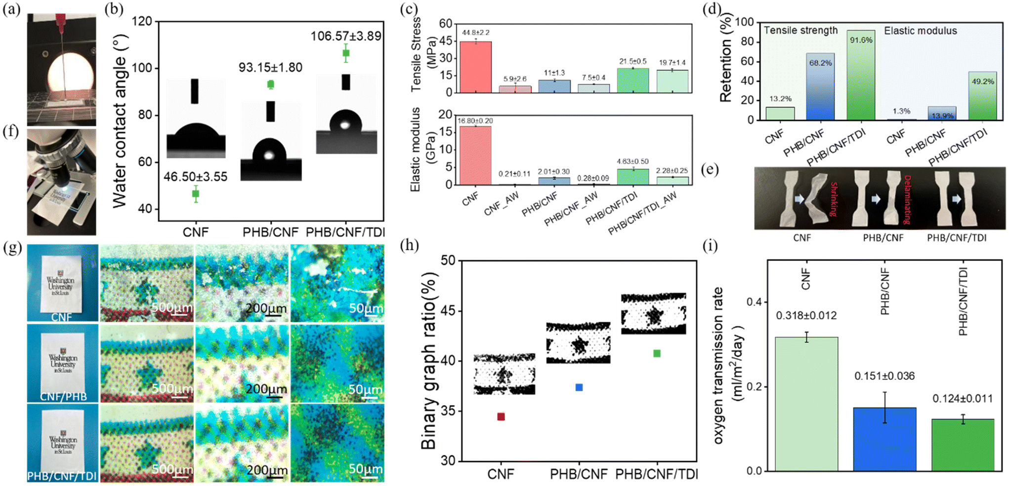 | ||
| Fig. 3 The characteristics and properties of the PHB-based films. (a) The image of surface water contact angle measurement. (b) The surface water contact angle of CNF, PHB/CNF and PHB/CNF/TDI (MReB)films. (c) The tensile stress and elastic modulus of CNF, PHB/CNF, and PHB/CNF/TDI (MReB) samples before and after the water absorbency test by soaking in water for 24 hours. (d) Strength retention of CNF, PHB/CNF, and PHB/CNF/TDI (MReB) samples after the water absorbency test. (e) Comparative images of the CNF, PHB/CNF, and PHB/CNF/TDI (MReB) samples before and after the water absorbency test. (f) The image of microscopic observation of the printed pattern on the PHB based films. (g) The printed patterns of CNF, PHB/CNF and PHB/CNF/TDI (MReB) films. (h) The printability of CNF, PHB/CNF, and PHB/CNF/TDI (MReB) films based on the binary graph ratio. (i) The oxygen transmission ratio of CNF, PHB/CNF and PHB/CNF/TDI (MReB) films. | ||
In order to further understand the water stability performance in practical applications, we performed the water absorbency test; the CNF, PHB/CNF, and MReB (PHB/CNF/TDI) samples were soaked in the water for 24 hours and then tested for their tensile properties. Fig. 3c shows the tensile stress and elastic modulus of the samples before and after the water absorbency test. The results highlighted that MReB held the highest tensile stress and elastic modulus after the water absorbency test, which remains to be at 19.7 MPa of tensile stress and 2.28 GPa of elastic modulus, representing the 8.4% reduction from 21.5 MPa of tensile stress and 50.8% reduction from the 4.63GPa of elastic modulus as compared to control MReB. However, the mechanical properties of PHB/CNF films without TDI significantly reduced by 33.8% to 7.5 MPa in tensile stress and by 86.1% in elastic modulus to 0.28 GPa, as compared to 11.0 MPa of tensile stress and 2.01 GPa of elastic modulus of control PHB/CNF sample (Fig. 3(d)). Notably, the CNF samples swelled after the water absorbency test, and the tensile stress and modulus of CNF samples significantly reduced compared with the PHB-based samples. The results highlighted that the MReB design both overcame interlayer properties’ repulsion and built a water stability layer for new functionality.
Fig. 3(e) shows the images of CNF, PHB/CNF, and MReB water-treated samples and the relevant drying samples after the water absorbency test. The CNF samples shrunk after drying, while the PHB/CNF sample without TDI crosslinking was delaminated. In contrast to the CNF sample and PHB/CNF sample, the MReB samples remained the same. The results highlighted that the MReB design addresses the challenges of repulsion between different polymer materials, creates a water-proof structure through cross-linking, overcomes the water-stability limits of cellulose nanomaterials while leveraging its strong mechanical strength, and ultimately achieves outstanding water stability.
The MReB design not only improves water stability but also achieves printability as a thermal printing material. Printability is an important function of the packaging industry. In general, both petroleum-based plastics such as PP, PE, etc. and biosynthetic polymers such as PHB, PLA, etc. cannot be printed using a thermal printer, i.e. laser printer, due to their unstable thermal properties and low viscosity at high temperatures. This imposes a significant limitation in the application, as these plastics often require additional layers or materials for printing, complicating the recycling. Considering that cellulose materials like paper are often printable, we carried out experiments to evaluate if MReB can achieve thermal printability. Binary graph analysis was utilized to process the printing areas shown in Fig. 3(f) and (g) to assess printing quality, as shown in Fig. 3(h). The analysis highlighted that the MReB design achieved excellent thermal printability. Interestingly, the MReB (PHB/CNF/TDI) film even achieved a more effective binary printed area than that of neat CNF, with an increase of 18.2%. The results highlighted that the TDI-crosslinking and the MReB design can create a more compact structure that benefits printability. Furthermore, the TDI residue test of the MReB was conducted using GCMS. No TDI-related peaks were observed in the results (see the ESI†). This indicates that all the TDI reacted with other components, thereby eliminating environmental concerns.55,56 The synergistic improvement of mechanical properties, water stability, and printability will substantially expand the application of the MReB films for broad packaging applications to address plastic contamination.
Besides mechanical properties, water stability, and printability, another important feature of packaging materials is low air permeability. We therefore performed the oxygen transmission test for these biodegradable films. MReB design achieved a very low oxygen transmission rate, as shown in Fig. 3(i). The results showed that the PHB/CNF films can achieve a lower oxygen transmission rate than that of the neat CNF film, doubling the resistant efficiency. The oxygen transmission rate for the PHB/CNF/TDI film was measured at 0.124 ml m−2 day−1, which is lower than that of the PHB/CNF film. The results highlighted that TDI crosslinking could have created a denser multilayer structure for the film, which in turn minimized the pores or defects to reduce oxygen permeability resistance (Fig. 3(h)). To further compare the performance of the films, we also compared the MReB film with common bioplastics of PLA57 as well as petroleum-based plastic films such as PE,58 PP,59 and PET.60 MReB achieved a substantial decrease of the oxygen transmission rates as compared to PE, PLA, PET, and PP. These discoveries further confirmed the potential of MReB for high-value packaging materials due to its excellent mechanical properties, thermal and water stability, printability, and oxygen transmission resistance.
3.6. The cellulose nanomaterials in MReB improved biodegradability and reduced the formation of microplastics
The substantial improvement of mechanical properties and multi-functionality will certainly promote broad applications. Nevertheless, considering the potential applications, it is critical to understand the environmental implications of MReB. We therefore carried out the biodegradability assay to observe the degradation rate and morphology transformation during biodegradation. The results highlighted that the MReB design achieved more efficient biodegradability, while improving mechanical properties and multi-functionality. Fig. 4(a) shows the weight changes over the course of 4 months for the PHB, CNF, PHB/TDI, PHB/CNF, MReB (PHB/CNF/TDI), control polypropylene (PP), and control polyethylene (PE) samples, respectively. Compared to the control polypropylene and polyethylene samples, all of the PHB-based composite films have undergone weight loss of varying extents during the first week of treatments. The results show that the MReB film (PHB/CNF/TDI) had the largest loss at around 38.5%, followed by the PHB/CNF, CNF, PHB, and PHB/TDI films, respectively. The results highlighted that CNF improves the degradation of PHB, as shown by the larger weight loss as compared to the PHB film (Fig. 4(a)). | ||
| Fig. 4 Degradation of PHB-based composite films. (a) The weight change percentage of PHB, CNF, PHB/TDI, PHB/CNF. PHB/CNF/TDI (MReB), control PE, and control PP, respectively. (b) The digital images of each sample at weeks 0, 4, 8 and 16, respectively. (c) The surface morphologies of the PHB film before degradation and after 8 weeks and 16 weeks of degradation. (d) The surface morphologies of the CNF film before degradation and after 8 weeks and 16 weeks of degradation. (e) The surface morphologies of the PHB/TDI film before degradation and after 8 weeks and 16 weeks of degradation. (f) The surface morphologies of the PHB/CNF film before degradation and after 8 weeks and 16 weeks of degradation. (g) The surface morphologies of the PHB/CNF/TDI (MReB) film before degradation and after 8 weeks and 16 weeks of degradation. (h) The microstructural changes, fungal biodegradation and bacterial biodegradation of the PHB/CNF/TDI (MReB) film after 16 weeks of degradation. | ||
Fig. 4(b) shows the digital images of each sample at week 0, week 4, week 8, and week 16. The images are consistent with the weight loss data, indicating that the microbes in the soil have promoted the degradation of the PHB composite films. More importantly, the PHB films degrade into much smaller pieces, while the MReB film holds together as larger pieces during degradation, despite more weight loss. PHB, like other plastics, can form microplastics causing additional environmental hazards.16,61 The morphological transformation indicated that the MReB design increases the degradation rate, but could prevent the formation of microplastics, considering that the film is holding together.
To gain a deeper understanding of the degradation mechanisms, the surface morphologies of each sample before and after degradation have been analyzed by SEM. The surface morphologies show that the PHB film lost its compact structure after approximately 8 weeks of degradation, as shown in Fig. 4(c). Nevertheless, the surface morphology of the CNF film shows a different degradation mechanism as compared to the PHB film, in which the materials were degraded by a mold-like fungus, as shown in Fig. 4(d). TDI cross-linking in MReB could both strengthen mechanical properties and prevent the breakdown of MReB into smaller pieces during degradation. As shown in Fig. 4(e), MReB holds a more compact structure as compared to the PHB film shown in Fig. 4(c). Furthermore, TDI could serve as an abundant nitrogen source to provide essential nutrients for microbial growth. The SEM image highlighted a different degradation mechanism for MReB as compared to other films. Filamentous fungi seem to play a role in degradation in the first 8 weeks, while other microorganisms might be involved in 16 weeks to achieve a higher level of decomposition. Overall, the results highlighted that the addition of CNF synergized the degradation of PHB-based film (Fig. 4(f)) and the TDI cross-linking has improved the degradation of the PHB/CNF composite film (Fig. 4(g)), instead of decreasing it. The results suggested that both physical decomposition and microbial biodegradation are important for biodegradation of MReB (Fig. 4(h)). More efficient microbial degradation does not necessarily depend on the physical decomposition but relies on the chemical composition. In that regard, CNF's glucose units and TDI's high nitrogen content may both promote the fungal and microbial degradation of MReB as shown by the surface morphology during degradation (Fig. 4(g) and (h)).
Based on the morphological transformation and degradation rate, we hereby summarize the two aforementioned mechanisms and their roles in MReB degradation in Fig. 5(a), (b), (c) and (d). As shown in Fig. 5(a), the PHB film decomposes into small pieces during physical decomposition, while the CNF film does not have substantial physical decomposition, but rather mainly undergoes more microbial degradation (Fig. 5(b)). This difference could be due to two effects. First, the PHB film is much more brittle as compared to the CNF film, making it more likely to undergo physical decomposition. Second, cellulose is composed of linear chains of glucose connected by β-1,4-glucosidic linkages. Cellulose is a natural substrate for many microorganisms, in particular, fungal species.3 When CNF and PHB were built into a composite, CNF could synergize the PHB degradation by recruiting and supporting microbes for PHB degradation (Fig. 5(c)). Furthermore, MReB achieved the most rapid degradation, indicating that TDI might have played a role in speeding up degradation (Fig. 5(d)). In general, the crosslinking agent tightens the interactions among different polymers to improve mechanical strength and durability, which should reduce the degradation rate due to its effects against physical decomposition. However, TDI's rich isocyanate functional group could have provided a nitrogen source to promote microbial degradation, leading to more efficient degradation of MReB. The chemical characteristics and physical strength indicate that microbial degradation is more predominant than physical decomposition during the MReB degradation process. The synergistic improvement of mechanical, thermal, and biodegradable properties allows TDI to be more broadly applied in biodegradable composite development. The design of MReB thus substantially improved mechanical strength and biodegradability through the synergistic effects of PHB, CNF, and TDI, while also achieving multi-functionality.
 | ||
| Fig. 5 The degradation mechanism and microbial community composition of the PHB-based composite film. (a) Proposed degradation mechanism I for PHB films: The PHB film without CNF decomposes from a large-sized film into small debris. (b) Proposed degradation mechanism II for CNF films: The CNF film undergoes microbial biodegradation. (c) Proposed degradation mechanism III for multi-layer PHB/CNF films: the multi-layer PHB/CNF film experiences a synergistic degradation effect, with both decomposition and biodegradation occurring simultaneously to facilitate the film's degradation. (d) The microbe promoting mechanism by the crosslinking agent TDI to degrade the PHB-based composite film. (e) Microbial community composition at the phylum level. (f) Microbial community composition at the class level. Taxa with relative abundance smaller than 0.01 across 50% of samples are grouped together and categorized as ‘others’. One biological replicate was used for each treatment condition. | ||
3.7. The differential recruitment of microorganisms accounts for the rapid biodegradation of MReB
In order to further understand the mechanisms for microbial degradation, we performed 16S amplicon sequencing and ITS amplicon sequencing to identify the microbial community for both bacteria and fungi. The results correlated with the degradation rate and morphological transformation, suggesting that differential microbial recruitments could have accounted for more rapid biodegradation of MReB. At the phylum level, bacterial communities were dominated by Proteobacteria and Actinobacteria (Fig. 5e) under all four conditions. The abundance of Actinobacteria in the bacterial communities from PHB/CNF and PHB/TDI films was higher than that in CNF and MReB films. Acidobacteriota, Myxococcota, Chloroflexi, Firmicutes, and Gemmatimonadota were more abundant in CNF and MReB films than in PHB/CNF and PHB/TDI films (Fig. 5(e)). Actinobacteria and Proteobacteria are known to synthesize PHA for energy storage under anaerobic conditions, and it is reasonable that they can degrade PHA as carbon sources.62,63Myxoccocus were particularly enriched in CNF and MReB samples. Some Myxoccocus have cellulose degradation capacity, and the results suggested that these bacteria could be promoted by the presence of cellulose. The most interesting finding was that the pattern of bacterial distribution is similar for CNF and MReB samples. The results suggested that when CNF is closely bound to PHB with TDI crosslinking, the samples can recruit cellulose degrading bacteria as effectively as CNF alone. Cellulose degradation bacteria are predominant in the MReB biodegradation process. Moreover, TDI facilitates the conversion of nitrogen nutrients, promoting microbial growth and thereby enhancing biodegradation.Similar phenomena were also found in fungi, although fungal community profiles showed a large divergence under the four conditions (Fig. 5(f)). Ascomycota was the dominant phylum under all conditions. Nevertheless, the classes of Ascomycota varied in different types of films. In CNF and MReB films, Sordariomycetes is the most abundant class and the second most abundant class, respectively. Eurotiomycetes is dominant in PHB/CNF and PHB samples. The results correlated with the previous discovery that Sordariomycetes and Eurotiomycetes are among the most predominant species for plastic degradation.64 The data indicate that Eurotiomycetes were more prevalent in the PHB/CNF film, and were suppressed in CNF and MReB films. Again, the results highlighted that CNF and MReB films have highly similar fungal distribution patterns. The results correlated well with the morphological data, in that CNF/TDI might have both held the MReB film together and promoted degradation, whereas CNF has recruited bacteria and fungi to drive more rapid degradation. Ultimately, CNF is glucose-based and might have provided a preferred substrate for microorganisms, empowering the more efficient degradation of MReB.
4. Conclusions
The MReB design can guide the future design of different types of bioplastics. The CNF reinforcement and TDI cross-linking created a unique structure that can leverage the strength of both bioplastics and cellulose nanomaterials, while creating new functionalities that do not exist in a single type of plastic. First, the MReB design has substantially improved the mechanical and thermal properties of PHB films. As compared to other studies in the field, the four times increase of Young's modulus in this study has achieved a record level as compared to the recent PHB composites (Table S4†). As compared to the conventional petrochemical plastics, this study shows a higher elastic modulus than those of most of the petrochemical materials and tensile strength comparable to those of HDPE, PS, PP, and others. When plastic products have low elastic moduli, large deformation would limit their applications. A high elastic modulus resists deformation and can empower the manufacturing of more robust plastic materials. MReB films with a high Young's modulus will significantly expand the application scope, especially in packaging, structural materials, and medical devices that require a higher stiffness.65Second, the unique design also took advantage of the glucose-based cellulose composition and the nitrogen containing TDI composition to empower the recruitment of new types of microorganisms for more rapid biodegradation. More importantly, the TDI crosslinking and cellulose nanofiber structure holds the structure of the MReB film to avoid decomposition to form microplastics. MReB thus leverages both the unique chemical composition and structure design to achieve multifaceted environmental benefits for both rapid biodegradation and secondary hazard reduction.
Third, the MReB design achieved new multi-functionalities that do not co-exist in current single types of bioplastics and petrochemical plastics. The multi-functionality in turn will promote broad applications in packaging industries, maximizing the environmental benefits. The structural design, in particular, TDI cross-linking of two functionally complementary bioplastics allows the leverage of the advantages of both types of materials. The synergistic achievement of water stability, low air permeability, and printability thus allow the MReB material to be broadly applied in the packaging industries. The multi-functionality addresses the challenges in application in ways that a single type of petrochemical plastic cannot achieve. The functional superiority could promote the utilization of this type of new biomaterial. Furthermore, recent technical breakthroughs have substantially reduced the price of cellulose nanomaterials, which makes MReB more affordable. Overall, the MReB design can overcome the limitations of bioplastics, achieve unique multi-functionality, and guide the future design of various biopolymer composites with broad applications.
Data availability
The authors confirm that the data supporting the findings of this study are available within the article and its ESI.†Conflicts of interest
The authors confirm that they are not affiliated with or involved in any organization or entity that has a financial or non-financial interest in the subject matter or materials covered in this article.Acknowledgements
The authors would like to acknowledge the U.S. National Science Foundation Project No. 2229160 and U.S. Department of Energy Projects DE EE 0009756 and DE EE 0007104 for their financial support.References
- J.-G. Rosenboom, R. Langer and G. Traverso, Nat. Rev. Mater., 2022, 7, 117–137 CrossRef PubMed
.
- A. K. Mohanty, S. Vivekanandhan, J.-M. Pin and M. Misra, Science, 2018, 362, 536–542 CrossRef CAS PubMed
- J. Li, C. Hu, J. Arreola-Vargas, K. Chen and J. S. Yuan, Trends Biotechnol., 2022, 40(12), 1535–1549 CrossRef CAS PubMed
- W. Zhang, P. Zhang, H. Wang, J. Li and S. Y. Dai, Trends Biotechnol., 2022, 40(12), 1519–1534 CrossRef CAS PubMed
- F. Gironi and V. Piemonte, Energy Sources, Part A, 2011, 33, 1949–1959 CrossRef CAS
- Y. Wu, J. Tian, M. Sun, L. Gao, J. Xu and Z. Niu, Green Chem., 2024, 26, 2851–2857 RSC
- J. Cavalcante, D. G. Oldal, M. V. Peskov, A. K. Beke, R. Hardian, U. Schwingenschlogl and G. Szekely, ACS Nano, 2024, 18, 7433–7443 CrossRef CAS PubMed
- L. Lin, Y. Cheng, Y. Pu, S. Sun, X. Li, M. Jin, E. A. Pierson, D. C. Gross, B. E. Dale, S. Y. Dai, A. J. Ragauskas and J. S. Yuan, Green Chem., 2016, 18, 5536–5547 RSC
- Z.-H. Liu, M. L. Olson, S. Shinde, X. Wang, N. Hao, C. G. Yoo, S. Bhagia, J. R. Dunlap, Y. Pu, K. C. Kao, A. J. Ragauskas, M. Jin and J. S. Yuan, Green Chem., 2017, 19, 4939–4955 RSC
- Z.-H. Liu, S. Shinde, S. Xie, N. Hao, F. Lin, M. Li, C. G. Yoo, A. J. Ragauskas and J. S. Yuan, Sustainable Energy Fuels, 2019, 3, 2024–2037 RSC
- P. Zhang, K. Chen, B. Xu, J. Li, C. Hu, J. S. Yuan and S. Y. Dai, Chem, 2022, 8, 3363–3381 CAS
- P. Dhar, U. Bhardwaj, A. Kumar and V. Katiyar, Polym. Eng. Sci., 2015, 55, 2388–2395 CrossRef CAS
- D. K. Mandal, H. Bhunia, P. K. Bajpai, A. Kumar, G. Madhu and G. B. Nando, J. Polym. Environ., 2018, 26, 1061–1071 CrossRef CAS
- X. Zhao, K. Cornish and Y. Vodovotz, Environ. Sci. Technol., 2020, 54, 4712–4732 CrossRef CAS PubMed
- C. Yang, F. Topuz, S.-H. Park and G. Szekely, Green Chem., 2022, 24, 5291–5303 Search PubMed
- M. González-Pleiter, M. Tamayo-Belda, G. Pulido-Reyes, G. Amariei, F. Leganés, R. Rosal and F. Fernández-Piñas, Environ. Sci.: Nano, 2019, 6, 1382–1392 RSC
- G. Kale, T. Kijchavengkul, R. Auras, M. Rubino, S. E. Selke and S. P. Singh, Macromol. Biosci., 2007, 7, 255–277 CrossRef CAS PubMed
- D. Ramakanth, K. Akhila, B. P. Kumar, K. K. Gaikwad and P. K. Maji, Green Chem., 2024, 26, 5293–5307 RSC
- C. M. Chan, L.-J. Vandi, S. Pratt, P. Halley, D. Richardson, A. Werker and B. Laycock, Polym. Rev., 2018, 58, 444–494 CrossRef CAS
- S. Singh and A. Mohanty, Compos. Sci. Technol., 2007, 67, 1753–1763 CrossRef CAS
- S. Christian and S. Billington, Composites, Part B, 2011, 42, 1920–1928 CrossRef
- J. Li, Q. Yan and Z. Cai, J. Sandwich Struct. Mater., 2021, 23, 1701–1716 CrossRef CAS
- J. Li, Q. Yan and Z. Cai, Cellulose, 2019, 26, 1769–1780 CrossRef CAS
- Z. Li, J. Yang and X. J. Loh, NPG Asia Mater., 2016, 8, e265 CrossRef CAS
- D. M. Panaitescu, E. R. Ionita, C.-A. Nicolae, A. R. Gabor, M. D. Ionita, R. Trusca, B.-E. Lixandru, I. Codita and G. Dinescu, Polymers, 2018, 10, 1249 CrossRef PubMed
- B. Thomas, M. C. Raj, J. Joy, A. Moores, G. L. Drisko and C. m. Sanchez, Chem. Rev., 2018, 118, 11575–11625 CrossRef CAS PubMed
- J. Sun, J. Shen, S. Chen, M. A. Cooper, H. Fu, D. Wu and Z. J. P. Yang, Polymers, 2018, 10, 505 CrossRef PubMed
- D. Jun, Z. Guomin, P. Mingzhu, Z. Leilei, L. Dagang and Z. Rui, Carbohydr. Polym., 2017, 168, 255–262 CrossRef PubMed
- A. N. Frone, D. Batalu, I. Chiulan, M. Oprea, A. R. Gabor, C.-A. Nicolae, V. Raditoiu, R. Trusca and D. M. Panaitescu, Nanomaterials, 2020, 10, 51 CrossRef CAS PubMed
- V. K. Rastogi and P. Samyn, eXPRESS Polym. Lett., 2020, 14, 115–133 CrossRef CAS
- D. Aydemir and D. J. Gardner, Carbohydr. Polym., 2020, 250, 116867 CrossRef CAS PubMed
-
A. Collins, Contact dewatering of cellulose nanofibers for biopolymer composite applications, The University of Maine, 2022 Search PubMed
- S. Shankar and J.-W. Rhim, Carbohydr. Polym., 2016, 135, 18–26 CrossRef CAS PubMed
- P. J. Barham, A. Keller, E. L. Otun and P. A. Holmes, J. Mater. Sci., 1984, 19, 2781–2794 CrossRef CAS
- L. F. Rivas, S. A. Casarin, N. C. Nepomuceno, M. I. Alencar, J. A. M. Agnelli, E. S. d. Medeiros, A. d. O. Wanderley Neto, M. P. d. Oliveira, A. M. d. Medeiros and A. S. Santos, Polimeros, 2017, 27, 122–128 CrossRef
- E. Bolyen, J. R. Rideout, M. R. Dillon, N. A. Bokulich, C. C. Abnet, G. A. Al-Ghalith, H. Alexander, E. J. Alm, M. Arumugam and F. Asnicar, Nat. Biotechnol., 2019, 37, 852–857 CrossRef CAS PubMed
- B. Callahan, P. McMurdie, M. Rosen, A. Han and A. Johnson, DADA2: high-resolution sample inference from Illumina amplicon data, Nat. Methods, 2016, 13, 581–583 CrossRef CAS PubMed
- R. H. Nilsson, K.-H. Larsson, A. F. S. Taylor, J. Bengtsson-Palme, T. S. Jeppesen, D. Schigel, P. Kennedy, K. Picard, F. O. Glöckner and L. Tedersoo, Nucleic Acids Res., 2019, 47, 259–264 CrossRef PubMed
-
H. Wickham, Reducing duplication, in ggplot2: Elegant Graphics for Data Analysis, Use R, Springer, New York, NY, 2009, ch. 10, pp. 177–182 Search PubMed
- H. Cox, Br. J. Appl. Phys., 1952, 3, 72 CrossRef
- W. Yan, J. Liu, X. Zheng, J. Zhang and K. Tang, e-Polym., 2023, 23, 20230010 CrossRef CAS
- H. E. Cainglet, J. Tanner, N. Nasiri, C. Browne, G. Garnier and W. Batchelor, Cellulose, 2023, 30, 4971–4982 CrossRef CAS
- Y. Liu, B. Li, W. Mao, W. Hu, G. Chen, Y. Liu and Z. Fang, ACS Omega, 2019, 4, 7861–7865 CrossRef CAS PubMed
- D. Bucci, L. Tavares and I. Sell, Polym. Test., 2005, 24, 564–571 CrossRef CAS
- I. T. Seoane, L. B. Manfredi, V. P. Cyras, L. Torre, E. Fortunati and D. Puglia, Polymers, 2017, 9, 561 CrossRef PubMed
- I. T. Seoane, P. Cerrutti, A. Vazquez, V. P. Cyras and L. B. Manfredi, Polym. Bull., 2019, 76, 967–988 CrossRef CAS
- Y. Zheng, J.-C. Chen, Y.-M. Ma and G.-Q. Chen, Metab. Eng., 2020, 58, 82–93 CrossRef CAS PubMed
- M. Kansiz, A. Domínguez-Vidal, D. McNaughton and B. Lendl, Anal. Bioanal. Chem., 2007, 388, 1207–1213 Search PubMed
- J. Xu, B.-H. Guo, R. Yang, Q. Wu, G.-Q. Chen and Z.-M. Zhang, Polymer, 2002, 43, 6893–6899 CrossRef CAS
-
M. Fan, D. Dai and B. Huang, Fourier transform infrared spectroscopy for natural fibres, InTech, 2012 Search PubMed
- T. Kondo and C. Sawatari, Polymer, 1996, 37, 393–399 CrossRef CAS
- P. Dhar, U. Bhardwaj, A. Kumar and V. Katiyar, Polym. Eng. Sci., 2015, 55, 2388–2395 CrossRef CAS
- H. Zhao, J. H. Kwak, Z. Conrad Zhang, H. M. Brown, B. W. Arey and J. E. Holladay, Carbohydr. Polym., 2007, 68, 235–241 CrossRef CAS
- D. Ciolacu, F. Ciolacu and V. I. Popa, Cellul. Chem. Technol., 2011, 45, 13 CAS
-
D. C. Allport, D. S. Gilbert and S. Outterside, MDI and TDI: safety, health and the environment: a source book and practical guide, John Wiley & Sons, 2003 Search PubMed
-
F. J. Davis and G. R. Mitchell, in Bio-materials and prototyping applications in medicine, Springer, 2008, pp. 27–48 Search PubMed
- V. Siracusa, P. Rocculi, S. Romani and M. Dalla Rosa, Trends Food Sci. Technol., 2008, 19, 634–643 CrossRef CAS
- P. Suppakul, J. Miltz, K. Sonneveld and S. W. Bigger, Packag. Technol. Sci., 2006, 19, 259–268 CrossRef CAS
- M. Buntinx, G. Willems, G. Knockaert, D. Adons, J. Yperman, R. Carleer and R. Peeters, Polymers, 2014, 6, 3019–3043 CrossRef
- I. Uysal Unalan, D. Boyacı, M. Ghaani, S. Trabattoni and S. Farris, Nanomaterials, 2016, 6, 244 CrossRef PubMed
- C. Wang, J. Yu, Y. Lu, D. Hua, X. Wang and X. Zou, Environ. Sci. Pollut. Res., 2021, 28, 66511–66518 CrossRef CAS PubMed
- A. Kawakoshi, H. Nakazawa, J. Fukada, M. Sasagawa, Y. Katano, S. Nakamura, A. Hosoyama, H. Sasaki, N. Ichikawa and S. Hanada, DNA Res., 2012, 19, 383–394 CrossRef CAS PubMed
- P. H. Janssen, Appl. Environ. Microbiol., 2006, 72, 1719–1728 CrossRef CAS PubMed
- A. H. Ekanayaka, S. Tibpromma, D. Dai, R. Xu, N. Suwannarach, S. L. Stephenson, C. Dao and S. C. Karunarathna, J. Fungi, 2022, 8, 772 CrossRef CAS PubMed
- P. G. Seligra, M. Lamanna and L. Famá, Procedia Mater. Sci., 2015, 8, 383–390 CrossRef CAS
Footnote |
| † Electronic supplementary information (ESI) available. See DOI: https://doi.org/10.1039/d4gc02440k |
| This journal is © The Royal Society of Chemistry 2025 |