
Microfluidic paper-based analytical soft actuators (μPAC)†
Koki
Yoshida
ab,
Masahiro
Tanakinoue
ac,
Hiroaki
Onoe
 d and
Michinao
Hashimoto
*b
d and
Michinao
Hashimoto
*b
aResearch Center for Autonomous Systems Materialogy, Institute of Integrated Research, Institute of Science Tokyo, Japan
bPillar of Engineering Product Development, Singapore University of Technology and Design, 8 Somapah Road, 487372, Singapore. E-mail: hashimoto@sutd.edu.sg; Tel: +65 6499 4867
cDepartment of Computer Science, Institute of Science Tokyo, 4259 Nagatsuta-cho, Midori-ku, Yokohama, Kanagawa 226-8502, Japan
dDepartment of Mechanical Engineering, Keio University, 3-14-1 Hiyoshi, Kohoku-ku, Yokohama, 223-8522, Japan
First published on 20th January 2025
Abstract
Soft actuators have developed over the last decade for diverse applications including industrial machines and biomedical devices. Integration of chemical sensors with soft actuators would be beneficial in analyzing chemical and environmental conditions, but there have been limited devices to achieve such sensing capabilities. In this work, we developed a thin-film soft actuator integrated with a paper-based chemical sensor, termed a microfluidic paper-based analytical soft actuator (μPAC). μPAC consists of (1) a silicone thin film with a 3D-printed pneumatic chamber and (2) a cellulose paper. This cellulose paper offers dual functions: the strain-limiting layer of a soft actuator and the substrate for the chemical sensor for a paper-based analytical device (μPAD). We characterized the design parameters of the actuators—namely, (1) thickness of silicone thin film, (2) chamber length, and (3) Young's modulus of silicone thin film—to evaluate the actuation performance. These characterizations suggested that the cellulose paper served as a suitable self-straining layer of the actuator, making μPAC a chemical sensor that can actuate simultaneously. Highlighting the unique capability of μPAC, we demonstrated the local detection of pH on the curved target surface. Overall, this research demonstrated the rapid fabrication of actuating chemical sensors with a unique design by combining soft actuators and μPAD, enabling chemical sensing on various surface topologies by dynamically making conformal contact.
Tribute to George WhitesidesHappy 85th birthday, George. When I joined graduate school in 2003, I aspired to become a theoretical scientist. Something unexpected happened, and I ended up doing experiments in the Whitesides group. This serendipity has shaped my career. The experience in the group allowed me to become a handyperson without limiting my curiosity to any specific discipline. It is not about being interdisciplinary or cross-disciplinary, but rather about creating new disciplines that did not exist before. Pioneering a discipline is a challenging but worthwhile goal, and I greatly benefited from seeing many excellent examples set by my colleagues in the early stages of my scientific career. In the lab, I worked closely with my senior colleague, Piotr Garstecki, on droplet microfluidics. I appreciated the philosophy of simple solutions in the group. I brought the idea of simple solutions to my research group, continuing to develop technologies that others can use. The topic we explored in this paper is built on two simple technologies—paper-based microfluidics and soft actuators—from the Whitesides group. With this, I hope to illustrate how I have continued to enjoy exploring science and engineering, building on the foundation laid in your group. Happy birthday, George, and many more to come!Michinao Hashimoto |
1. Introduction
This work developed actuatable chemical sensors, termed a microfluidic paper-based analytical soft actuator (μPAC). Soft actuators have been developed over the last decade due to their flexibility and compliance with applications for industrial machines, biomedical devices, and wearable devices.1–5 Unlike conventional rigid counterparts operated by electrical inputs, soft grippers can be controlled by heat,6 light,7 air pressure,8 or liquid displacement.9,10 Such characteristics offer various advantages, including conformability, complex motion, and reduced energy consumption. In particular, pneumatic soft grippers, consisting of pneumatic chambers and microchannels, are widely used due to their simple control without mechanical components.11–14 Pneumatic chambers typically consist of soft elastomers combined with different Young's modulus components to achieve anisotropic deformation.15,16 Different approaches—such as embedding paper,17 reinforcing with fibers (e.g., polyaramid fibers18,19 and cotton threads20), increasing the number of layers,21 knitting,22 and regulating balloon inflation23,24—have been used to achieve asymmetric strain, leading to programmed deformation of the actuator. The deformation can be designed by the geometry and the arrangement of materials comprising the actuator;23,25 different modes of actuation have been demonstrated, such as expanding,17 contracting,15 twisting,26 and bending.27 Soft actuators are often fabricated by casting the silicone elastomer in the negative molds. Polydimethylsiloxane (PDMS) and Ecoflex are widely used silicone elastomers due to their processability, biocompatibility, and stretchability. Recent advances in 3D printing have enabled alternative ways to fabricate soft actuators. Stereolithography and extrusion 3D printing have been utilized to pattern various materials to create microchannels and chambers.28–32 These technologies are applied to the fabrication of soft actuators, including milli-meter scale pneumatic soft grippers by multi-material digital light processing (DLP)-based 3D printing33 and biodegradable soft actuators by fused deposition modeling (FDM) printing.20More recently, the integration of sensors with soft actuators has been demonstrated to self-sense the condition of the actuator.34–36 Successful demonstrations are shown for sensing proximity14 and own strain.37 The capability to sense the state of the soft actuators offers precise control for the actuation. Electrical sensing of the surrounding conditions (e.g., tactile sensing of the surface) has also drawn remarkable attention.14,37,38 On the other hand, integrating chemical sensors with soft actuators is essential to identify the chemical and environmental conditions, including pH and material concentrations, which will find various practical applications in agriculture and healthcare. Hydrogel with biomolecules (e.g., DNA and enzyme) or synthetic bacteria have been used as soft and compliant materials for surface chemical sensing because hydrogel can permeate molecules, withholding the sensing elements.39–42 Alternatively, porous materials (such as cellulose papers) have been widely explored as a substrate for colorimetric chemical sensing.43,44 Paper-based chemical sensors are primarily constructed by immersing colorimetric sensor inks into microchannels made with molten wax.45,46 Despite its desired characteristics, however, the direct integration of cellulose paper substrates with soft actuators to perform chemical sensing has not been explored.
Here, we present a thin-film soft actuator integrated with a paper-based chemical sensor, termed a microfluidic paper-based analytical soft actuator (μPAC, Fig. 1a). μPAC consisted of (1) silicone-based microchannels as pneumatic chambers and (2) a wax-based chemical reservoir. Crucially, both components can be digitally patterned by DIW 3D printing. The paper substrate offered dual functions: the strain-limiting layer of a soft actuator and the substrate for a microfluidic paper-based analytical device (μPAD). The silicone chambers were expanded by pneumatic pressure, leading to the deformation of μPAC in a similar manner to conventional pneumatic actuators (Fig. 1b). We performed parametric studies for the bending behaviors of μPAC by changing the geometric parameters: chamber size, thickness, and Young's modulus. Then, the repeated actuation of the μPAC was demonstrated. μPAC can deform and make conformal contact with a target object to detect surface chemical conditions, illustrated by colorimetric pH sensing (Fig. 1c). Overall, we developed a unique design of actuatable paper-based chemical sensors by combining a paper-based fluidic system with an elastomeric actuator in a single device, termed μPAC. The paper substrate is designed as part of the actuator that can move and conform to the surface being analyzed. We envisage that the unique capability of μPAC could lead to diverse applications. For example, integrating μPAC into a soft robotic gripper for agricultural and food products may enable on-site detection of chemical contaminants during handling.47–49 μPAC could also be used for sampling of the physiological lumen when mounted on the tip of an endoscope.50 Additionally, μPAC might be used to capture environmental samples by the integration with aerial robots.51,52 These application scopes highlight the versatility of μPAC across different disciplines, from healthcare to environmental monitoring.
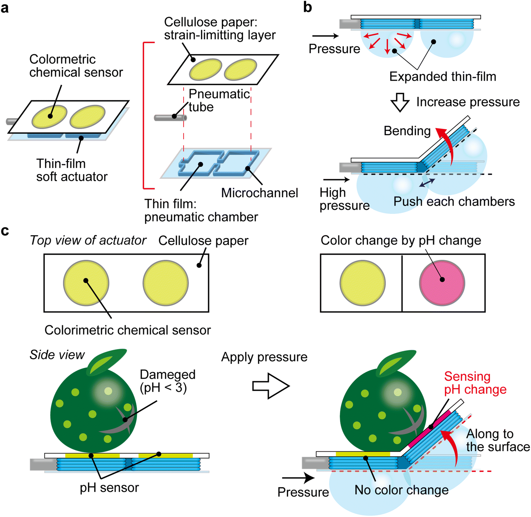 | ||
| Fig. 1 Schematic illustration of a microfluidic paper-based analytical soft actuator (μPAC). (a) Illustration of μPAC. μPAC consists of (1) cellulose paper and (2) silicone sealant printed on a silicone thin film. A silicone tube (i.e., pneumatic tube) is inserted to the microchannel to apply pressure. (b) Expansion of the pneumatic chambers. The pneumatic chambers are expanded by the pressure applied through the pneumatic tube. The expansion of the chambers leads to the bending motion. (c) Integration of chemical sensors with the soft actuator. The paper-based substrate is placed as a strain-limiting layer of the soft actuator. This layer simultaneously serves as a substrate for chemical sensing, which conformally contract with the surface where the soft actuator is in contact. As an example, colorimetric pH sensing by μPAC is illustrated. | ||
2. Experimental design
2.1. Selection of materials
The objective of this research is to investigate ways to integrate a soft actuator with a chemical sensor. We selected the cellulose paper as a substrate of the soft actuator due to its desirable properties: (1) permeable to aqueous solutions, (2) not stretchable yet flexible, and (3) porous. The permeability to aqueous solutions enables the handling of aqueous samples and chemical sensing as demonstrated in μPAD. Cellulose papers have also been widely used as origami or kirigami structures to create deformable structures, allowing reversible deformation required for the actuation. Lastly, the cellulose paper is porous, which enables the physical integration of composite materials. In this research, the printed silicone elastomer was mechanically interlocked with a paper substrate to achieve a stable bonding between the elastomer and the substrate. The molten wax was also printed on the paper to create hydrophobic regions on the paper, which was essential for creating analytical domains for aqueous samples.2.2. Selection of fabrication methods
Conventional pneumatic actuators have complex three-dimensional (3D) designs, and they combine materials with different stiffness for actuation. In this work, we aimed to simplify the fabrication process for rapid manufacturing. We proposed an alternative design of a soft actuator that could be fabricated by DIW printing. In our design, 3D-printed square microchambers were sandwiched between pre-fabricated thin-film substrates with different stiffness: a silicone thin film and a cellulose paper. The different stiffness is crucial for bending motion (ESI S1,† Fig. S1). Fabrication of soft actuators was achieved by printing the outlines of two-dimensional (2D) microfluidic chambers.53 This approach reduces the materials and time required to create microchambers in comparison with molding. Crucially, μPAD can be also fabricated by DIW printing, which is also an essential component of the device we intend to achieve. Overall, due to the design of the actuator, and the applicable printing materials (i.e., silicone resin and wax), DIW printing was used to perform the fabrication of μPAC.3. Results and discussion
3.1. Bending characteristics of μPAC
Fig. 1 illustrates the concept of the current research. A proposed μPAC have pneumatic chambers with a square length (7.5 mm or 10 mm) (Fig. 2a). The microchannel connecting pneumatic chambers were 2 mm in length and 2 mm in width. For fabricating the pneumatic chamber with microchannels, the silicone sealant was printed by a DIW printer on the thin-film elastomeric substrates (Ecoflex 0-10 and Ecoflex 00-30, Fig. 2b). Young's modulus of the cured Ecoflex 00-10 and Ecoflex 00-30 were 41 kPa,54 169.4 kPa,55 respectively. The silicon tube (outer diameter: 1 mm) was placed on the printed silicone sealant microchannel. The additional silicone sealant was then printed on the silicone tube to immobilize them. After that, the cellulose paper was set on the printed microchannel. The printed silicone sealant was solidified overnight together with the cellulose paper, promoting the integration of the printed sealant with the cellulose paper (Fig. 2c). We created the actuator consisting of two square chambers in the front and the back to study the bending behaviors.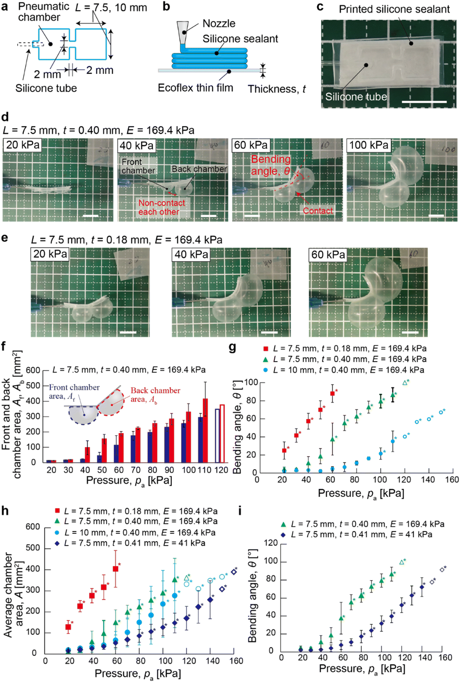 | ||
| Fig. 2 Characterization of the bending motion of μPAC. (a) Design of the microchamber of μPAC. (b) Schematic illustration of the printing of the silicone sealant, and the thickness of the thin film (t). (c) Photograph showing a fabricated μPAC. (d and e) Photographs showing the bending behavior of μPAC with increasing pressure (pa), with different thickness of the film: (d) 0.40 mm and (e) 0.18 mm. (f) Plot showing the areas of the front chamber (Af) and the back chamber (Ab) with respect to pressure (pa). (g) Plot showing the bending angle of μPAC (θ) with respect to pressure (pa), (h) plot showing the average chamber areas of μPAC (A) with respect to pressure (pa). (i) Plot showing the bending angles of μPAC (θ) with respect to pressure (pa). The physical parameters of μPAC (L, t, E) are indicated in each plot. In all plots, unfilled marks suggest the measurement was performed less than triplicate (n = 3). The asterisk (*) suggests when two pneumatic chambers are in contact. Scale bars: 10 mm. | ||
To actuate μPAC, the pneumatic pressure was applied through the silicone tube using an air dispenser at a constant pneumatic pressure. The elastomeric chambers expanded and reached a steady state due to the contact pressure applied to the chamber (Fig. 2d). The expanded chambers maintained the shape, suggesting the outflow of the gas through the cellulose paper can be compensated by the inflow of the gas to the chamber. When the two adjacent pneumatic chambers became sufficiently large to push against each other, μPAC exhibited the bending motion. The degree of actuation of μPAC was affected by altering the thickness of the silicone thin film (Fig. 2e).
To perform a detailed characterization of bending behaviours, we altered the pneumatic pressure (pa), the thickness of the thin silicone film (t), the chamber length (L) and Young's modulus of the elastomer (E). The pneumatic pressure (pa) was increased from 20 kPa in increments of 10 kPa, repeating the process until the elastomeric layer of μPAC was ruptured. When applying the pneumatic pressure (pa = 20 kPa) to μPAC with L = 7.5 mm, t = 0.40 mm, and E = 169.4 kPa, the actuator hardly bent (with the bending angle, θ = 4.6 ± 2.0°). In this case, the pneumatic chambers slightly expanded (with the cross-sectional chamber area A = 12.8 ± 2.0 mm2), and did not push each other (Fig. 2d, left and 2f). When the pneumatic pressure increased to pa = 40 kPa, the pneumatic chamber expanded (Fig. 2d). In this chamber design, the cross-sectional area of the back chamber, Ab = 97.4 ± 45.7 mm2, was larger than the front chamber area, Af = 21.2 ± 4.2 mm2 (Fig. 2f). When increasing the pneumatic pressure the pneumatic to pa = 60 kPa, the pneumatic chambers further expanded and pushed each other (Af = 112.7 ± 63.8 mm2, Ab = 188.4 ± 14.6 mm2), leading to bending of μPAC with θ = 37.6 ± 17.7°. The chamber area and bending angle were increased as the pneumatic pressure increased (Fig. 2f and g, green triangles). The bending angle of μPAC (θ) ranged from 4.6 ± 2.0° to 87.0 ± 7.8° when the pneumatic pressure (pa) ranged from 20 kPa to 110 kPa (Fig. 2f, green triangles). The silicone thin film with t = 0.40 mm withstood the pressure up to pa ∼ 110 kPa; the same silicone thin film in the chamber burst at Pa ∼ 120 kPa. These results suggested that bending behavior largely depended on the expansion of the pneumatic chambers resulting in mutual pushing. It is also worth noting that the silicone thin film burst before the adhesive detached, suggesting that the printed silicone sealant tightly bonded both sides of the films (i.e., the silicone thin film and the cellulose paper).
Next, we used the thinner silicone film (t = 0.18 mm) to evaluate the bending characteristics of μPAC (L = 7.5 mm and E = 169.4 kPa). At the reduced pneumatic pressure (pa = 20 kPa), this design of μPAC expanded with average chamber area, A = 128.2 ± 31.1 mm2 and bent with θ = 24.9 ± 9.5° (Fig. 2e, left and 2h, red square). The bending angle of the μPAC (θ) ranged from 24.9 ± 9.5° μm to 88.0 ± 9.8° μm when the pneumatic pressure (pa) ranged from 20 kPa to 60 kPa (Fig. 2g, red scares). Similar to the design of μPAC with t = 0.40 mm, the back chamber was more readily expanded than the front chamber (details in ESI† S2, Fig. S2). While the pneumatic chamber was readily expanded by the applied pressure, the thin film was broken at Pa ∼ 70 kPa. The maximum bending angle and the average chamber area were θ = 88.0 ± 9.8° and A = 404.7 ± 87.2 mm2. These values were similar to the device with the larger film thickness (t = 0.40 mm; θ = 87.0 ± 7.8°, A = 354.1 ± 100.5 mm2). These results suggested that the bending behavior of μPAC was dependent on the expansion of the pneumatic chambers. The responsiveness of μPAC to the applied pressure can be controlled by the thickness of the silicone thin film. In addition, the thickness of the silicone thin film did not influence the maximum bending angle for the two devices we studied (t = 0.18 mm and 0.40 mm) while the tolerances of the pneumatic chamber were different.
Then, we changed the side length of the square chamber to L = 10 mm (t = 0.40 mm, E = 169.4 kPa). A relatively small pneumatic pressure (pa < 90 kPa) did not bend the actuator (θ < 20°). The average chamber area increased slightly due to the expansion of the back chamber, but the actuator did not bend because the two chambers did not contact (Fig. 2g, sky blue circles, 2h, sky blue circles, and S3†). The maximum bending angle was θ = 35.1 ± 11.4° (pa = 110 kPa), which was much smaller than the actuator with L = 7.5 mm (θ = 86.7 ± 7.8°). These results indicated that the increased chamber size caused large contrasts in the expansion behaviors between the front chamber and back chamber, resulting in less bending of μPAC. The maximum chamber area (A = 277.7 ± 152.4 mm2) was also smaller than μPAC with t = 0.40 mm and L = 7.5 mm because of the imbalance of expansion. The maximum pneumatic pressure before the rapture of the silicone thin film remained as pa = 110 kPa (that was the same as the actuator with t = 0.40 mm and L = 7.5 mm), indicating that the chamber size did not influence the tolerance of the thin film actuator.
Lastly, we examined the bending behavior of μPAC using a thin film with a low Young's modulus (E = 41 kPa) and the same dimensions (L = 7.5 mm and t = 0.41 mm). In this case, the chambers in the actuator required high pneumatic pressure to expand. The average chamber area ranged from 14.7 ± 2.0 mm2 to 258.0 ± 9.5 mm2 when the pneumatic pressure (pa) ranged from 20 kPa to 140 kPa (Fig. 2h, blue diamonds). The average chamber area at the maximum pneumatic pressure (before the rapture of the film) was smaller than μPAC with E = 169.4 kPa (354.1 ± 100.5 mm2, Fig. 2h, green triangle). This result indicated that the reduced Young's modulus of the film increased the maximum pneumatic pressure that could be withheld without rapturing. Previous research verified that the soft thin film (Ecoflex 00-10) could withstand more strain than the hard thin film (Ecoflex 00-50).56 The bending angle ranged from θ = 2.1 ± 2.1° (Pa = 20 kPa) to θ = 72.2 ± 10.4° (Pa = 140 kPa, Fig. 2i, blue diamonds). The bending angles of μPAC with E = 41 kPa were approximately the same as μPAC with E = 169.4 kPa when the average chamber area was approximately the same; for example, θ = 39.7 ± 7.0° (E = 41 kPa, A = 147.5 ± 47.0 mm2, Pa = 110 kPa) and θ = 37.6 ± 17.7° (E = 169.4 kPa, A = 150.5 ± 59.8 mm2, Pa = 60 kPa) were comparable (Fig. S4a†). Overall, the range of the bending angle was comparable regardless of two Young's modulus of the thin film (E = 41 kPa and 169.4 kPa) we studied, while the higher pneumatic pressure was required to achieve the same bending angles for the actuator with the lower Young's modulus. When changing the thickness (t) and the chamber length (L), the expansion and bending behavior of μPAC (E = 41 kPa) exhibited similar trends to those with the high Young's modulus (E = 169.4 kPa) (details in ESI† S4, Fig. S4b).
Overall, this study identified three major parameters—(1) the thickness of the silicon thin film, (2) the chamber size, and (3) Young's modulus of the silicone thin film—to control the expansion and bending behaviors of μPAC. The thickness of the silicone thin film and Young's modulus largely influenced the range of the pneumatic pressure that the μPAC could withstand. μPAC fabricated with the thicker or softer film could withstand the larger pressure, while the higher pressure was required to expand the pneumatic chamber. The bending angle was determined by the chamber area, and it is thus possible to change its responsiveness to pneumatic pressure by changing the thickness and Young's modulus. Other parameters, such as the distance between adjacent pneumatic chambers and the mechanical properties of the cellulose paper (e.g., thickness and pore size), would influence the bending behaviors. Lastly, creating proper contact between pneumatic chambers is critical to achieving the actuation, and the design of the pneumatic chamber (e.g., a circle-shaped chamber, triangle-shaped chamber, and parallelogram-shaped chamber) should induce complex patterns of actuation, which is left for further investigation.
When enlarging the chamber size, the imbalance of expansion occurred between the front chamber and the back chambers, resulting in the small bending angle of μPAC at the low pneumatic pressure. We believe this asymmetry of the expansion can be attributed to the design of the chambers; the front chamber is anchored by three sides by the silicone sealant (with one side having the airpath) while the back chamber is anchored by two sides by the silicone sealants (with two sides having the airpath). This difference in the geometry of the chambers caused the back chamber more prone to expand than the front chamber when the same pressure was applied simultaneously.
3.2. Repeated actuation of the thin-film soft-actuator
To characterize the performance of μPAC, we considered two types of repeatability in this study: (1) the repeatability of the bending performance of the pneumatic soft actuator and (2) the reusability of the integrated paper-based sensor. We first observed the repeatability of the actuation of μPAC by cyclic application of pressure, pa = 100 kPa with intervals of 5 s (Movie S1†). The pneumatic chamber expanded immediately as the pressure was applied, and the bending angle (θ) was gradually increased from 62° (1 s) to 79° (5 s) while the pressure was applied (Fig. 3a and b). The pneumatic chamber deflated as soon as the applied pressure was stopped, and the bending angle (θ) decreased to 21° (10 s). The deformation of the cellulose paper was not completely reverted to the initial straight state. The actuations were performed five times, and a gradual increase in bending angle was observed after each cycle.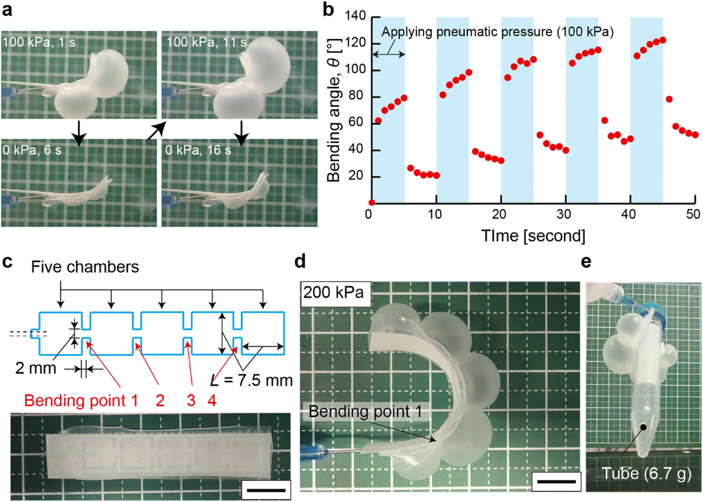 | ||
| Fig. 3 Demonstration of μPAC. (a) Photogaraphs showing repeated actuation of μPAC. (b) Plot showing the bending angle of μPAC (θ) over time, with repeated actuation. (c) Design and photograph of μPAC with five pneumatic chambers. (d) Photograph showing the bending of μPAC with five pneumatic chambers. (e) Photograph showing the gripping of a test tube by μPAC with five pneumatic chambers. Scale bars: 10 mm. | ||
3.3. μPAC as a soft gripper
We designed μPAC with five pneumatic chambers to demonstrate gripping like an octopus arm (Fig. 3c). The chamber length was 7.5 mm, and the interval of chambers was 2 mm. When applying 200 kPa to the μPAC with five pneumatic chambers, all chambers were successfully expanded (Fig. 3d). These results showed that μPAC can be actuated with an increased number of chambers. In this experiment, the bending angle of the pneumatic chamber having pneumatic microchannels on both sides (Point 2 and Point 3) was larger than the pneumatic chamber with one side closed (Point 4). This observation indicated that the configuration and the arrangement of the pneumatic chamber influenced the bending behavior (details in ESI† S5, Fig. S5). To demonstrate the gripping motion, μPAC with five pneumatic chambers was actuated to catch a tube (6.7 g weight) by applying a constant pressure (pa = 200 kPa). μPAC with five pneumatic chambers wrapped the side of the tube and held the tube while lifted (Fig. 3e). This result indicated that μPAC can be potentially used as a soft, pneumatic gripper with a flexible design of gripping arms.The presence of multiple chambers allows complex motion of μPAC, demonstrating wrapping, gripping, and grasping with 360° of rotation (details in ESI† S6, Fig. S6). The chambers can be designed in two dimensions to achieve motions on more than two planes (Fig. S6b and d†). We believe complex motions, such as hand-like motion with multiple fingers with independent motions, and actuation that conforms to curved surfaces, can be achieved using the design of the actuators that we presented. For applying μPAC to conventional robotics, it is essential to characterize the forces generated by the actuator. Detailed characterization of the forces generated by different designs of μPAC is under current investigation.
3.4. Paper-based microfluidic colorimetric chemical sensor integrated soft μPAC
Finally, we demonstrated that μPAC was applied to perform chemical sensing during the actuation. To demonstrate the principle, we performed pH sensing of a spherical-shaped target by creating a conformal contact along the surface of the target objects. To fabricate the pH sensor, molten paraffin wax was circularly printed (diameter 4 mm) on the cellulose paper substrate (Fig. 4a, top). The printed wax vertically penetrated through the cellulose paper, which would inhibit the mechanical interlocking between the cellulose paper and the silicone sealant. As such, it is crucial to avoid overlapping the print path of the wax with the print path of the silicone sealant. The printed paraffin wax served as a hydrophobic barrier to confine the pH indicator. The color of the pH indicator changed in response to the pH, and thus the pH of the target samples can be estimated using the hue value of the indicator (details in ESI† S7, Fig. S7). After fabricating two colorimetric pH sensors on the cellulose paper, the cellulose paper substrate was integrated into the soft actuator (L = 7.5 mm, t = 1.8 mm, and E = 169.4 kPa) (Fig. 4a, bottom). μPAC with colorimetric pH sensors was designed to test the top (region A) and the side (region B) of the spherical object simultaneously (Fig. 4b). A small lime was used as the sensing target; the damage on the surface caused reduced pH due to the seeping of the acidic juice (Fig. 4c). Three target samples—a non-damaged sample, an entirely damaged sample, and a partially damaged sample—were prepared to perform experiments with an appropriate control (Table 1). The pH indicator used in this experiment underwent a color change to red when the pH was below 3. The ratio of red to green values in the RGB spectrum (Vr and Vg) was measured before and after sensing, and the ratio of the change (Rc) was calculated to quantify the color change as in eqn (1). | (1) |
 | ||
| Fig. 4 pH sensing with μPAC. (a) Illustration of colorimetric pH sensors integrated with μPAC. (b) Illustration of the application of pH-sensing μPAC on a small line sample. (c) Photographs of the entirely damaged target (sample 2) and the partially damaged target (sample 3). (d) Photographs showing the application of μPAC on a line sample. Application of the pressure allows the actuation of the sensing region to the detection area of the sample. (e) Photographs showing the color change of three samples (samples 1, 2, 3). (f) Plot showing the color change ratio (Rc) comparing the detection of the non-damaged and damaged surfaces. The asterisk (*) indicates a significant difference observed in a one-sided t-test (t < 0.05). The scale bars: 10 mm. | ||
| Region | ||
|---|---|---|
| A | B | |
| Sample 1: Non-damaged sample | Undamaged | Undamaged |
| Sample 2: Entirely damaged sample | Damaged | Damaged |
| Sample 3: Partially damaged sample | Undamaged | Damaged |
This demonstration suggested that μPAC enabled spatially-resolved chemical sensing on the curved surface by actuation. Altering the design of the pneumatic chambers makes it possible to tailor the motion of the soft actuators for intended applications. Silicone-based (or polymer-based) soft actuators exhibit selected chemical resistance compared to metal-based actuators (such as acid–base and reduction–oxidation reactions). With the realization of low-cost, single-use actuators equipped with chemical sensors, emerging applications such as simultaneous detection of food spoilage while sample collection would be possible. The capability to actuate the sensing region of the device would be potentially beneficial to ensure proper collection of the testing samples when remote operation is needed. To this end, our demonstration employed a pH indicator exhibiting discernible color changes upon the change in pH. Using the same platform, it is possible to embed other types of colorimetric inks to alter the sensing capability. For example, a paper-based temperature sensor was readily developed with thermochromic ink, which displayed pronounced color changes with observable differences (hue = 214.5 and 344.5) (ESI† S10, Fig. S10). Appropriate selection of colorimetric reagents is critical for successful chemical sensing tailored to specific applications.
We note that the repeated use of μPAC (i.e., the reusability) was not demonstrated in this work because the pneumatic actuator was directly integrated with the paper-based sensing region. In the current design, the cellulose paper serves for dual purpose: (1) the substrate to perform chemical sensing, and (2) the strain-limiting layer to bend the soft actuator. Similarly to μPAD, the sensor was meant to be disposable and used only one time. The reusability of μPAC would require a different device design that allows the separation of the sensor from the actuator. Alternatively, the complete washing to remove the reagents and the samples from the paper substrate may facilitate the repeated usage of μPAC. However, the feasibility would depend on the nature of the sensing reaction performed on μPAC. Nevertheless, because the cellulose paper and the silicone elastomer are readily available at low cost, the current design of μPAC would be suitable for a one-time sensor.
Conclusions
In this research, we demonstrated the concept of the thin-film soft actuator integrated with a paper-based chemical sensor, termed a microfluidic paper-based analytical soft actuator (μPAC). A cellulose paper in μPAC serves dual purposes: (1) strain-limiting layer of the soft actuator, and (2) porous substrate to hold analytical reagents for chemical sensing. μPAC (t = 0.40 mm, L = 7.5 mm, and E = 169.4 kPa) exhibited the bending motion with θ = 87.0 ± 7.8° by applying pneumatic pressure (pa = 110 kPa), where the bending angle was readily controlled with the applied pressure. We identified that the thickness and Young's modulus of the elastomeric thin film are major variables to control the expansion of the pneumatic chamber. μPAC can be designed to perform gripping motion (holding a tube with 6.7 g weight). Lastly, pH detection on a spherical surface was demonstrated by integrating pH sensing reagents with μPAC. The actuation of μPAC allowed conformal contact of the paper-based substrate with the curved surface of the sample, allowing pH detention at different locations of the spherical sample simultaneously.μPAC offers distinct advantages over conventional soft actuators. First, μPAC can be readily fabricated by DIW printing with low-cost materials. DIW printing allows the printing of various materials (e.g., silicone sealant and paraffin wax) on different substrates (e.g., cellulose papers and polymer films), which is suitable for rapid prototyping. The mode of actuation (such as gripping, grasping, and wrapping) can be readily tailored by the design of the printed microchambers, Integration of actuators with chemical sensors opens up a myriad of applications in agriculture, environmental sensing and healthcare. The capability to actuate the sensing region of the analytical device may benefit in scenarios where the simultaneous collection of the samples is necessary at different locations. We believe that μPAC paves an avenue for designing paper-based analytical devices with unprecedented usage that requires actuation of the chemical sensors.
Experimental section/materials and methods
The silicone sealant was filled with the syringe (PSY-50F, Musashi Engineering Inc., Tokyo, Japan) and printed by using a commercially available liquid dispenser (SHOT MASTER 500 ΩX, Musashi Engineering Inc., Tokyo, Japan) through a 22 G plastic nozzle (Birmingham Gauge) (V-S Liquid control equipment, China). The syringe filled with the silicone sealant, the plastic nozzle, and the liquid dispenser were maintained at room temperature. Four layers of the silicone sealant were printed on the Ecoflex film. After printing the silicone sealant, a silicone tube (SR-1554, ARAM Corporation, Osaka, Japan) was placed on the edge of the pneumatic chamber as an inlet of air. Then the additional silicone sealant was printed on the tube. The cellulose paper (Grade 1, Whatman, Sigma-Aldrich, Singapore) was placed on the printed silicone sealant. The printed silicone sealant was cured overnight. The printing toolpath was designed by MuCAD (Musashi Engineering Inc., Tokyo, Japan).
μPAC (L = 7.5 mm, t = 0.17 mm) was fabricated with Ecoflex 00-10 thin film for repeated actuation. The pneumatic pressure of 100 kPa was applied at a five-second interval. The movie showing the actuation of μPAC was taken by the compact digital camera, and then the images were captured from the movie every second. The bending angle, θ, was measured every second by using ImageJ.
Data availability
The data that support the findings of this study are available from the corresponding author upon reasonable request.Conflicts of interest
There are no conflicts to declare.Acknowledgements
K. Y. acknowledges the Research Fellowship for Young Scientists PD (22J01492) and Grant-in-Aid for Early-Career Scientists (23K13289), Japan Society for the Promotion of Science (JSPS), JAPAN. M. H. acknowledges Digital Manufacturing and Design (DManD) Centre at the Singapore University of Technology and Design (RGDM1620403), Agency for Science, Technology, and Research (A*STAR) (M22K2c0085), and Ministry of Education (MOE), Singapore (Academic Research Fund (AcRF) Tier 2, MOE-T2EP50122-0025) for the project funding.References
- J. Kim, J. W. Kim, H. C. Kim, L. Zhai, H. U. Ko and R. M. Muthoka, Int. J. Precis. Eng. Manuf., 2019, 20, 2221–2241 CrossRef
.
- D. Rus and M. T. Tolley, Nature, 2015, 521, 467–475 CrossRef CAS PubMed
- C. Laschi, B. Mazzolai and M. Cianchetti, Sci. Robot., 2016, 1(1), 1–11 Search PubMed
- P. Won, K. K. Kim, H. Kim, J. J. Park, I. Ha, J. Shin, J. Jung, H. Cho, J. Kwon, H. Lee and S. H. Ko, Adv. Mater., 2021, 33(19), 1–19 Search PubMed
- S. I. Rich, R. J. Wood and C. Majidi, Nat. Electron., 2018, 1, 102–112 CrossRef
- K. Yoshida, S. Nakajima, R. Kawano and H. Onoe, Sens. Actuators, B, 2018, 272, 361–368 CrossRef CAS
- Y. Takashima, S. Hatanaka, M. Otsubo, M. Nakahata, T. Kakuta, A. Hashidzume, H. Yamaguchi and A. Harada, Nat. Commun., 2012, 3(1270), 1–8 Search PubMed
- B. Mosadegh, P. Polygerinos, C. Keplinger, S. Wennstedt, R. F. Shepherd, U. Gupta, J. Shim, K. Bertoldi, C. J. Walsh and G. M. Whitesides, Adv. Funct. Mater., 2014, 24(15), 2163–2170 CrossRef CAS
- E. Acome, S. K. Mitchell, T. G. Morrissey, M. B. Emmett, C. Benjamin, M. King, M. Radakovitz and C. Keplinger, Science, 2018, 359(6371), 61–65 CrossRef CAS PubMed
- V. Cacucciolo, J. Shintake, Y. Kuwajima, S. Maeda, D. Floreano and H. Shea, Nature, 2019, 572, 516–519 CrossRef CAS PubMed
- P. Polygerinos, N. Correll, S. A. Morin, B. Mosadegh, C. D. Onal, K. Petersen, M. Cianchetti, M. T. Tolley and R. F. Shepherd, Adv. Eng. Mater., 2017, 19(12), 1–22 CrossRef CAS
- M. S. Xavier, C. D. Tawk, A. Zolfagharian, J. Pinskier, D. Howard, T. Young, J. Lai, S. M. Harrison, Y. K. Yong, M. Bodaghi and A. J. Fleming, IEEE Access, 2022, 10, 59442–59485 Search PubMed
- B. Gorissen, D. Reynaerts, S. Konishi, K. Yoshida, J. W. Kim and M. De Volder, Adv. Mater., 2017, 29(43), 1–14 CrossRef PubMed
- T. H. Yang, J. Shintake, R. Kanno, C. R. Kao and J. Mizuno, Adv. Intell. Syst., 2020, 2(8), 1–7 Search PubMed
- M. Schaffner, J. A. Faber, L. Pianegonda, P. A. Rühs, F. Coulter and A. R. Studart, Nat. Commun., 2018, 9(878), 1–9 CAS
- R. F. Shepherd, F. Ilievski, W. Choi, S. A. Morin, A. A. Stokes, A. D. Mazzeo, X. Chen, M. Wang and G. M. Whitesides, Proc. Natl. Acad. Sci. U. S. A., 2011, 108(51), 20400–20403 CrossRef CAS PubMed
- R. V. Martinez, C. R. Fish, X. Chen and G. M. Whitesides, Adv. Funct. Mater., 2012, 22(7), 1376–1384 CrossRef CAS
- R. F. Shepherd, A. A. Stokes, R. M. D. Nunes and G. M. Whitesides, Adv. Mater., 2013, 25(46), 6709–6713 CrossRef CAS PubMed
- A. Yamaguchi, K. Takemura, S. Yokota and K. Edamura, Sens. Actuators, A, 2011, 170(1–2), 139–146 CrossRef CAS
- A. Heiden, D. Preninger, L. Lehner, M. Baumgartner, M. Drack, E. Woritzka, D. Schiller, R. Gerstmayr, F. Hartmann and M. Kaltenbrunner, Sci. Robot., 2022, 7(63), 1–10 Search PubMed
- A. A. Amiri Moghadam, S. Alaie, S. Deb Nath, M. Aghasizade Shaarbaf, J. K. Min, S. Dunham and B. Mosadegh, Soft Robot., 2018, 5(4), 443–451 CrossRef PubMed
- V. Sanchez, K. Mahadevan, G. Ohlson, M. A. Graule, M. C. Yuen, C. B. Teeple, J. C. Weaver, J. McCann, K. Bertoldi and R. J. Wood, Adv. Funct. Mater., 2023, 33(26), 1–12 Search PubMed
- Y. Hori and S. Konishi, Microsyst. Nanoeng., 2023, 9(55), 1–12 Search PubMed
- S. Russo, T. Ranzani, C. J. Walsh and R. J. Wood, Adv. Mater. Technol., 2017, 2(10), 1–12 Search PubMed
- B. Gorissen, D. Reynaerts, S. Konishi, K. Yoshida, J. W. Kim and M. De Volder, Adv. Mater., 2017, 29(43), 1–14 CrossRef PubMed
- B. Gorissen, T. Chishiro, S. Shimomura, D. Reynaerts, M. De Volder and S. Konishi, Sens. Actuators, A, 2014, 216, 426–431 CrossRef CAS
- B. Mosadegh, P. Polygerinos, C. Keplinger, S. Wennstedt, R. F. Shepherd, U. Gupta, J. Shim, K. Bertoldi, C. J. Walsh and G. M. Whitesides, Adv. Funct. Mater., 2014, 24(15), 2163–2170 CrossRef CAS
- T. Ching, Y. Li, R. Karyappa, A. Ohno, Y. C. Toh and M. Hashimoto, Sens. Actuators, B, 2019, 297(126609), 1–9 Search PubMed
- K. Yamagishi, T. Ching, N. Chian, M. Tan, W. Zhou, S. Y. Huang and M. Hashimoto, Adv. Funct. Mater., 2023, 34(31), 1–11 Search PubMed
- K. Yamagishi, W. Zhou, T. Ching, S. Y. Huang and M. Hashimoto, Adv. Mat., 2021, 33(26), 1–15 CrossRef PubMed
- M. Wehner, R. L. Truby, D. J. Fitzgerald, B. Mosadegh, G. M. Whitesides, J. A. Lewis and R. J. Wood, Nature, 2016, 536, 451–455 CrossRef CAS PubMed
- W. Wu, A. Deconinck and J. A. Lewis, Adv. Mat., 2011, 23(24), 178–183 Search PubMed
- Y. F. Zhang, C. J. X. Ng, Z. Chen, W. Zhang, S. Panjwani, K. Kowsari, H. Y. Yang and Q. Ge, Adv. Mater. Technol., 2019, 4(10), 1–9 Search PubMed
- P. Zhou, J. Lin, W. Zhang, Z. Luo and L. Chen, Nano Res., 2022, 15(6), 5376–5383 CrossRef CAS
- L. Chen, M. Weng, P. Zhou, F. Huang, C. Liu, S. Fan and W. Zhang, Adv. Funct. Mater., 2019, 29(5), 1–9 Search PubMed
- J. Chen, K. Han, J. Luo, L. Xu, W. Tang and Z. L. Wang, Nano Energy, 2022, 70(105171), 1–8 Search PubMed
- H. Zhao, K. O'brien, S. Li and R. F. Shepherd, Sci. Robot., 2016, 1(1), 1–10 Search PubMed
- R. L. Truby, M. Wehner, A. K. Grosskopf, D. M. Vogt, S. G. M. Uzel, R. J. Wood and J. A. Lewis, Adv. Mat., 2018, 30(15), 1–8 Search PubMed
- K. B. Justus, T. Hellebrekers, D. D. Lewis, A. Wood, C. Ingham, C. Majidi, P. R. Leduc and C. Tan, Sci. Robot., 2019, 4(31), 1–7 Search PubMed
- C. Xu, Y. Song, J. R. Sempionatto, S. A. Solomon, Y. Yu, H. Y. Y. Nyein, R. Y. Tay, J. Li, W. Heng, J. Min, A. Lao, T. K. Hsiai, J. A. Sumner and W. Gao, Nat. Electron., 2024, 7, 168–179 CrossRef CAS PubMed
- Z. Xiong, S. Achavananthadith, S. Lian, L. Edward Madden, Z. Xin Ong, W. Chua, V. Kalidasan, Z. Li, Z. Liu, P. Singh, H. Yang, S. P. Heussler, S. M. P. Kalaiselvi, M. B. H. Breese, H. Yao, Y. Gao, K. Sanmugam, B. C. K. Tee, P.-Y. Chen, W. Loke, C. Teck Lim, G. S. H. Chiang, B. Y. Tan, H. Li, D. L. Becker and J. S. Ho, Sci. Adv., 2021, 7(47), 1–11 Search PubMed
- Y. Yu, J. Li, S. A. Solomon, J. Min, J. Tu, W. Guo, C. Xu, Y. Song and W. Gao, Sci. Robot., 2022, 7(67), 1–12 Search PubMed
- D. Kim, Y. Cao, D. Mariappan, M. S. Bono, A. J. Hart and B. Marelli, Adv. Funct. Mater., 2021, 31(1), 1–9 Search PubMed
- K. Yamada, H. Shibata, K. Suzuki and D. Citterio, Lab Chip, 2017, 17(7), 1206–1249 RSC
- J. S. Ng and M. Hashimoto, RSC Adv., 2020, 10(50), 29797–29807 RSC
- E. Carrilho, A. W. Martinez and G. M. Whitesides, Anal. Chem., 2009, 81(16), 7091–7095 CrossRef CAS PubMed
- Y. Yamanaka, S. Katagiri, H. Nabae, K. Suzumori and G. Endo, Proceedings of the 2020 IEEE/SICE, 2020, 87–92 Search PubMed
- Y. Liu, J. Hou, C. Li and X. Wang, Adv. Intell. Syst., 2023, 5(12), 1–30 Search PubMed
- R. K. Mishra, L. J. Hubble, A. Martin, R. Kumar, A. Barfidokht, J. Kim, M. M. Musameh, I. L. Kyratzis and J. Wang, ACS Sens., 2017, 2(4), 553–561 CrossRef CAS PubMed
- S. Russo, T. Ranzani, C. J. Walsh and R. J. Wood, Adv. Mater. Technol., 2017, 2(10), 1–12 Search PubMed
- T. Ching, J. Lee, S. Win, L. Win, D. Sufiyan, C. Lim, N. Nagaraju, Y. Toh, S. Foong and M. Hashimoto, Sci. Robot., 2024, 9(92), 1–13 Search PubMed
- E. Aucone, S. Kirchgeorg, A. Valentini, L. Pellissier, K. Deiner and S. Mitchev, Sci. Robot., 2023, 8(74), 1–13 Search PubMed
- T. Ching, Y. Li, R. Karyappa, A. Ohno, Y. C. Toh and M. Hashimoto, Sens. Actuators, B, 2019, 297(126609), 1–9 Search PubMed
- S. Zhao, C. C. Nguyen, T. T. Hoang, T. N. Do and H. P. Phan, Sensors, 2023, 23(12), 1–14 Search PubMed
-
A. Atieh, Design, Modeling, Fabrication and Testing of a Piezoresistive-Based Tactile Sensor for Minimally Invasive Surgery Applications, Master's Thesis, Concordia University, 2012 Search PubMed
- Z. Liao, M. Hossain and X. Yao, Mech. Mater., 2020, 144(103366), 1–12 Search PubMed
Footnote |
| † Electronic supplementary information (ESI) available. See DOI: https://doi.org/10.1039/d4lc00602j |
| This journal is © The Royal Society of Chemistry 2025 |