
 Open Access Article
 This Open Access Article is licensed under a
 Creative Commons Attribution 3.0 Unported Licence
Assessing the role of morphological changes as the origin of improved cycling stability of Sn-based anodes for sodium-ion batteries†
Carla Albenga a,
James A. Gotta,
Amalie Skurtveitb,
Jason M. Warnetta,
Faduma M. Maddara,
Alexey Y. Koposovbc,
Gustavo Pinzónd,
Geoff Westa and
Ivana Hasa*a
a,
James A. Gotta,
Amalie Skurtveitb,
Jason M. Warnetta,
Faduma M. Maddara,
Alexey Y. Koposovbc,
Gustavo Pinzónd,
Geoff Westa and
Ivana Hasa*a
aWMG, University of Warwick Coventry, CV4 7AL, UK. E-mail: ivana.hasa@warwick.ac.uk
bCentre for Materials Science and Nanotechnology, Department of Chemistry, University of Oslo, Blindern, 0315 Oslo, Norway
cDepartment of Battery Technology, Institute for Energy Technology (IFE), 2007 Kjeller, Norway
dEuropean Synchrotron Radiation Facility, Grenoble, France
First published on 21st May 2025
Abstract
Tin (Sn) is a promising anode material for sodium-ion batteries (NIBs) due to its high theoretical capacity, good conductivity and higher density compared to hard carbon, which could significantly increase energy density. However, the substantial volume changes Sn undergoes during (de-)sodiation typically result in mechanical degradation and unstable solid-electrolyte interphase (SEI). While recent research has reported unexpectedly stable cycling of micrometric Sn anodes in ether-based electrolytes, the mechanisms behind this performance remain underexplored. In this work, we investigate the influence of both Sn content and particle size on the structural and electrochemical stability of Sn-based electrodes. Contrary to expectations, increasing the Sn content does not compromise the cycling stability. Instead, higher Sn loading facilitates the formation of a robust bicontinuous porous architecture, known as coral-like structure, which enhances electrode resilience by distributing mechanical stress and accommodating volumetric expansion. This morphology is particularly prevalent in Sn-rich electrodes, where sufficient Sn enables extended structural connectivity during cycling. Interestingly, smaller Sn particles (submicron and nanoscale) result in poorer cycling performance, underscoring the importance of both particle size and network formation in achieving mechanical robustness. Moreover, we demonstrate that the development and propagation of the coral-like framework are contingent not only on the initial Sn content but also on the degree of sodiation. While Sn-rich anodes cycled in half-cells achieve a fully sodiated crystalline phase that supports dense network formation, in full-cell configurations the full sodiation is not achieved, leading to the formation of a less dense and continuous porous structures that are more susceptible to cracking. These insights highlight the need for full-cell optimization to promote complete sodiation and unlock the full potential of Sn-based anodes in practical NIB applications with higher energy density.
1 Introduction
Sodium-ion batteries (NIBs) have attracted increasing attention as a potential low-cost alternative to lithium-ion batteries (LIBs), particularly to those using a combination of lithium iron phosphate (LFP) and graphite. Abundance and availability of the raw materials employed and the compatibility with existing LIBs manufacturing lines are encouraging more battery manufacturers to adopt NIBs production, with the promise of lower long-term costs.Yao et al.1 recently examined how factors such as energy density and supply chain dynamics influence when NIBs might become more economical than LFP-based LIBs. NIBs were found to gain competitive advantage during disruptions in the lithium-ion supply chain such as high lithium prices or graphite shortages. However, their cost-effectiveness declines if the sodium-ion supply chain, particularly segments involving nickel, faces similar strains. The cost advantage traditionally associated with NIBs is currently challenged by the continuous price decrease of LFP/graphite LIB cells,2 making it increasingly important to enhance NIBs' energy density while preserving low manufacturing cost. A viable solution, beside improving cost/performance properties of the cathode chemistries employed, relies on the implementation of alternative anode materials.
Alloying-type anode materials, primarily from group IV and V elements of the periodic table, are capable of reversibly forming alloys with lithium (Li) and sodium (Na) offering high theoretical capacity for alkali-ion batteries. Among the alloying anode materials silicon (Si), the leading alternative to graphite in LIBs, has not shown ability to alloy with Na.3 Phosphorous (P) offers the highest theoretical capacity (2596 mA h g−1) but its poor electronic conductivity necessitates the use of conductive carbon, lowering the overall energy density. Lead (Pb) presents a good conductivity but exhibits a lower capacity (485 mA h g−1) as well as a mild toxicity. However, owing to its low cost and high recycling rates as well as its ubiquity in Pb–acid batteries, it has been well investigated in recent studies as a possible anode for NIBs.4,5 Antimony (Sb), germanium (Ge) and bismuth (Bi) have been explored, however their lower abundance and high cost makes them less appealing for application in industrially relevant NIBs.6
Tin (Sn) stands out as a highly promising candidate due to its high theoretical capacity (847 mA h g−1), good electrical conductivity, relatively high abundance and environmental friendliness.6 Additionally, the significantly higher density of Sn (∼7.31 g cm−3)1 compared to hard carbon (HC) (∼0.9 g cm−3)7 offers a potential for a marked increase in energy density (W h L−1).
Recent modelling studies by Yao et al.1 reported a comparison between sodium nickel manganese layered oxide (NaNM)|Sn and NaNM|HC cells leading to approximatively 30% reduction in initial price, while also suggesting the need for continued cathode development work to maintain long-term competitiveness. Furthermore, a recent announcement by UNIGRID Inc. (San Diego, California, USA) in partnership with Sodion Energy Pte. Ltd (Tamil Nadu, India) highlights the feasibility of the implementation of Sn in industrially relevant sodium chromite (NaCrO2, NCO)|Sn cells.8 Nanode Battery Technologies (Alberta, Canada) has also reported major advancements claiming a cycle life exceeding 5000 cycles along with fast-charging capabilities (6 min).9
Despite its potential, Sn, like the other alloying systems, undergoes significant volumetric expansion during sodiation leading to mechanical degradation, unstable solid-electrolyte interphase (SEI), and eventual cell failure.10 Nanostructuring of Sn can buffer volume changes but often reduces energy density and increases production cost and complexity.10 Introducing carbon-based conductive additives has been proposed as a strategy to mitigate the deleterious effects of volumetric expansion, counterbalancing mechanical strain and providing conductive pathways.11–13 Many studies reported on the use of nanostructured carbon matrices such as carbon nanofibers or nanotubes, graphene or amorphous carbon, which resulted in irreversible capacity associated to Na trapping or reduction of the overall active material mass in the electrode.6 Despite the benefits of this approach the use of a carbon matrix, being generally electrochemically inactive, decreases the overall capacity of the electrode affecting the energy density of the cell. Sn and Pb exhibit some of the larger volumetric expansions (420% and 390%, respectively) during Na alloying due to the much lower density of the final alloy compared to the pristine material.5,14 Yet, when cycled in ether-based electrolytes (e.g. monoglyme or diglyme) even micrometric Sn and Pb show unexpected stable electrochemical performance.
Zhang et al.14 first reported the superior performance of micrometric Sn (μ-Sn) cycled in diglyme compared to the same material tested in standard carbonate-based electrolytes. The electrodes revealed outstanding behaviour, outperforming many other nanostructured Sn-based materials,15,16 with a first coulombic efficiency (FCE) of 92% and a capacity retention of 88%. The SEM analysis revealed a smooth surface and high integrity of the Sn electrode after 100 cycles, attributed to the thin and robust SEI layer able to keep the electrode together limiting cracking and delamination.
Further studies carried out by Kim et al.17,18 explored the morphological evolution of μ-Sn electrodes cycled in ether-based electrolyte highlighting the growth of a mechanically robust and porous “coral-like structure” after many cycles. The same structural changes were reported for μ-Sn powders mixed with different carbon additives to form a composite electrode and for a Sn foil electrode (binder-free and additive-free), underlining that the phenomenon is imputable solely to metallic Sn independently from the electrode composition. These findings redirected the focus of the investigation from nano-sized or nanostructured Sn particles to bulk Sn anodes, paving the way for the development of new approaches to improve Sn anodes performance in NIBs. This resilience towards volumetric expansion is attributed to the formation of a unique bicontinuous porous framework.4,5,19 referred to as “coral-like structure” that mitigates volumetric expansion and prevents electrode breakdown.
However, the mechanism behind the formation of the “coral-like structure” and its effectiveness in alleviating the effects of volume expansion still need to be clarified, as well as the role of the glyme-based electrolyte in facilitating and sustaining the robust Sn-network.20,21
In this work, the structure–performance relationship of Sn-based anodes is explored to uncover the correlation between electrode composition, active material particle size and electrochemical response during the Na–Sn (de-)alloying process. The influence of the electrode composition on the cycling stability, capacity and rate capability was evaluated using HC as a matrix to improve the structural stability of Sn anodes while contributing to the overall capacity. Contrary to expectations, our findings reveal that increasing the Sn content does not compromise cycling stability. Indeed, Sn-rich electrodes composed of μ-Sn and HC exhibit comparable cycling stability to HC-rich electrodes yet deliver a significantly higher capacity. It is found that higher Sn loading facilitates the formation of a robust bicontinuous porous “coral-like structure". The structure was tracked using ex situ cross sectional scanning electron microscopy with energy dispersive X-ray analysis (SEM-EDS) and Phase Contrast X-ray computed tomography (XCT) of cycled Sn-rich electrodes, revealing its propagation throughout the electrode thickness after extended cycling and the particle size reduction of Sn upon de-alloying. Interestingly, smaller Sn particles (submicron and nanoscale) result in poorer cycling performance, underscoring the importance of both particle size and Sn content in the formation of the coral-like structure.
To assess real-world viability, Sn-based anodes were assembled into full-cells using Prussian White (PW) as the cathode material. Interestingly, the coral-like structure only partially formed in full-cell configurations. This behaviour was investigated using a combination of focus ion beam (FIB)-SEM, ex situ and operando X-ray diffraction (XRD), and electrochemical analysis to gain deeper insight into the degradation mechanism of Sn-based anodes. It was found that the distinctive coral-like morphology can form and extend throughout the electrode only when a fully sodiated crystalline phase is formed. Only with an extended coral-like structure an effective mitigation of the effects of the volumetric expansion can be achieved by allowing particle size reduction of Sn upon de-alloying with the consequent formation of a dense Sn metallic network.
2 Experimental section
2.1 Materials
Sn powders with different particle size (<150 nm; <10 μm, <45 μm, latter corresponding to −325 mesh) were purchased from Sigma Aldrich and are here referred to as nanometric, sub-micrometric Sn and micrometric (μ-Sn) respectively. The Sn materials were used as received for electrodes preparation. The three materials were investigated as mixtures with KURANODE™ Type 2 Hard Carbon (HC) (d50 = 5 μm). Sn and HC were thoroughly mixed by means of a Thinky mixer (Thinky ARE-250, Intertronics) in various weight ratios to obtain the Sn/HC active materials. Specifically, the Sn/HC ratio varied in weight% as follows 80![[thin space (1/6-em)]](https://www.rsc.org/images/entities/char_2009.gif) :20 (SnHC82), 60:40 (SnHC64), 40:60 (SnHC46), and 20:80 (SnHC28).
:20 (SnHC82), 60:40 (SnHC64), 40:60 (SnHC46), and 20:80 (SnHC28).
2.2 Characterization
Scanning Electron Microscopy (SEM) was used to evaluate the particle size and morphology of the different Sn powders by a Zeiss Sigma FE-SEM (Zeiss, Germany). The same instrument was used to obtain images of the pristine and cycled electrode's cross-sections. The electrodes were transferred from the Glovebox to a Hitachi broad beam Ion Milling System (IM4000 plus) equipped with an air-protection unit where the cross-sectional milling was carried out with an acceleration voltage of 4 kV for 1 hour and 30 minutes. The milled samples were then analysed by SEM using an acceleration voltage of 5–10 kV. Energy Dispersive X-ray (EDS) spectroscopy was used to map the elements in the electrodes. The samples were transferred between the different equipment using air-less transfer vessels to avoid air exposure causing undesired reactions.A Dualbeam Field Emission Gun Scanning Electron Microscope (FEG-SEM) with a Plasma Focused Ion Beam (PFIB) system (Thermo Fisher Scientific Helios 5 Hydra CX) was also used to explore the electrodes' morphology in more detail by performing 3D FIB-SEM tomography. A sample area was first prepared by broad beam ion milling as previously described, and then transferred, with Al foil at the top, to the PFIB system using the CleanConnect inert gas transfer system. A 200 μm wide 100 μm deep volume was selected for analysis. Trench cuts were made using a 30 kV 400 nA Ar beam. Thermo Fisher Scientific Auto Slice and View software V5 was used to automatically cut and image the volume. Slices with a nominal thickness 75 nm were cut using a 30 kV 28 nA Ar beam with automated stage rocking (rocking tilt of 5°). Backscattered electrons (BSE) SEM images were acquired every 150 nm with 2 kV 400 pA beam conditions. The FIB-SEM tomography data were aligned using Avizo 2023.1 (Thermo Fisher Scientific, USA) software.
The samples for phase contrast XCT were prepared by first transferring a piece of electrode (with Al foil at the top) and a sharpened carbon rod to a Thermo Fisher Scientific Helios 5 Hydra CX PFIB using the CleanConnect inert gas transfer system. A 150 μm wide and 150 μm deep piece of the electrode was cut using a 30 kV 500 nA Xe beam and then extracted by welding to a lift-out needle. Carbon deposition was used when welding to avoid adding to the sample any heavy element which strongly absorb X-rays. The extracted sample was then mounted on a 1 mm diameter carbon rod that had been filed down to a point and were mounted in huber pins sized to fit in the sample stage of ID16B beam line at European Synchrotron Radiation Facility (ESRF, Grenoble, France) and secured with carbon welding. The sample was then transferred back with air protection to a glovebox, encapsulated with a Kapton cover and sealed with epoxy adhesive to protect it from air exposure.
Phase contrast XCT was carried out at the ID16B beamline at ESRF. The beam operated at 29.6 keV with projections captured on a PCO camera at 2048 × 2048 pixels – further details on the instrument arrangement in the hutch can be found in ref. 22. Holographic XCT was the chosen imaging trajectory where projections are acquired through 360 degrees at four different source-object distances. The Paganin method was used for phase retrieval of the projections, which were then reconstructed using standard Filtered Back Projection. The samples were imaged at 100 nm for full field of view, followed by region of interest imaging at 30 nm in the centre of the sample to understand finer resolution features. This resulted in imaging volumes of 204.8 μm3 and 61.44 μm3 respectively.
Image analysis of the resultant tomographies was performed in Avizo 2023.1 (Thermo Fisher Scientific, USA). As shown in the resultant image slices, Sn is clearly distinguishable from the rest of the electrode. For this reason, an Otsu thresholding method was used to segment the Sn from the rest of the electrode to observe the spatial distribution in 3D. With the Sn identified, a particle size analysis was performed calculating both the volume and equivalent diameter enabling calculation of the volume distribution of distinct connected particles, and identification of unreacted Sn in the cycled samples that remained spherical. The thickness of the electrodes (without the current collector) was calculated by segmentation of the electrode surface and considering the average height perpendicular to the current collector.
X-ray diffraction (XRD) measurements of the pristine powders and electrode samples were carried out using a Malvern PANalytical Aeris diffractometer (40 kV, 15 mA) with non-monochromatic Cu Kα radiation (λKα1 = 1.540562 Å, λKα2 = 1.544390 Å). A Ni Cu-Kβ filter, a soller slit (0.04 rad), a divergence slit (1/4°) and a 13 mm X-ray mask were used on the incident beam side. An anti-scatter (9 mm) and soller (0.04 rad) slits were used on the diffracted beam side. Data was collected in Bragg–Brentano mode using a zero background Si holder while spinning, between an angular range of 5–60° (2θ) for the electrodes and 20–90° for the powders, with a step size of 0.02° and time per step of ∼200 s using a PIXcel1D-Medipix3 detector. Electrodes were transferred from an argon-filled glovebox into the instrument by using a zero background Si holder covered with kapton film to prevent air exposure during the measurement.
For the ex situ analysis, all the cells were stopped at 1.5 V and then disassembled in an argon-filled glovebox. Electrodes were recovered in the de-sodiated state and were washed with dimethyl carbonate (DMC) to eliminate electrolyte residuals.
Operando XRD (Bruker D8-A25 powder diffractometer with Mo radiation, λKα1 = 0.7093 Å, λKα2 = 0.7136 Å, focusing mirror primary optic) available at the Norwegian National Resource Centre for X-ray Diffraction and Scattering (RECX) was used to obtain the diffraction pattern of the Sn-based anodes while performing galvanostatic cycling with an SP150 battery cycler (BioLogic). The instrument is equipped with a Dectris Eiger 2 R 500k 2D area detector, which was used in 1D mode. The operando cell was assembled as described by Drozhzhin et al.23 using specifically designed cells equipped with two sapphire windows transparent to the X-ray radiation and hard enough to ensure constant pressure in the cell. The half-cell was assembled using a Na disk as the counter electrode from which a hole was cut in the middle corresponding to the sapphire window to reduce its signal contribution in the XRD pattern. 225 μL of electrolyte were added on the Glass fibre separators (Whatman, grade GF/A) during cell assembly. Such high quantity was required to compensate for a potential electrolyte leakage during cycling with the operando cell setup and to ensure that electrolyte consumption would not be a limiting factor during prolonged cycling.
2.3 Electrode processing and electrochemical testing
Electrodes were prepared by mixing the active materials powders (Sn and HC) in different weight ratios, maintaining the total wt% of active material in the electrodes at 90% resulting in Sn/HC amount (%) of 72/18 for SnHC82, 54/36 for SnHC64, 36/54 for SnHC46, and 18/72 for SnHC28. The active material was first mixed with carbon black (C45, Imerys), a solution of carboxymethyl cellulose (CMC) (Bondwell BVH8, Ashland) in water was added to the dry mix and finally styrene–butadiene rubber (SBR) (BM-451B, Zeon) in the proportion 90.0:5.0:2.5:2.5, respectively, to prepare a slurry. Deionized water was used as the solvent and all the components were mixed in a Thinky mixer (Thinky ARE-250, Intertronics). The slurry was then coated onto a 15 μm thick aluminium foil (Avotec Steel) using a doctor blade on a coater (Coatmaster 510 XL. Erichsen). The resulting coatings were dried in a Binder oven under ambient atmosphere at 60 °C for 48 hours. The micro-Sn/HC composite electrodes described in section 3.1 were calendered using a roller press calender (Innovative Machine Corp.) to ensure adequate adhesion to the current collector and facilitate the SEM analysis by preventing delamination during milling of the samples. The Sn/HC electrodes described in the Section 3.2 are not calendered. Electrodes were then cut into discs (Ø15 mm for two electrode coin cells, 12 mm for three-electrode Swagelok type cells and 18 mm for three-electrode EL-cells) and dried under vacuum in a glass oven (B-585, Buchi) at 120 °C for 12 hours.
The Sn-based electrodes had a mass loading ranging from 2.5–5 mg cm−2 with an areal capacity of 1–2.5 mA h cm−2.
Cell assembly was carried out in an argon-filled glove box (MBraun LABstar) with a H2O and O2 content lower than 0.5 ppm. In the half-cell configuration, Na metal was cut from Na pieces (99.8%, Acros Organics) and used as the counter electrode (and reference electrode in the T-cell format). Two 16 mm diameter glass fibre separators (Whatman, grade GF/A) were soaked in 120 μL of electrolyte. 1 M sodium hexafluorophosphate (NaPF6) solution in either diglyme (Fluorochem Ltd) or a mixture of ethylene carbonate (EC):diethylene carbonate (DEC) in a ratio of 3:7 (v/v%) (Fluorochem Ltd) were used as the electrolyte. Galvanostatic cycling tests were conducted within the 0.01–1.5 V voltage range, with a battery tester (BCS-805, Biologic), applying a constant current of ∼50 mA g−1 for the first cycle and ∼100 mA g−1 for the following cycles. These current density values correspond to different C-rates, depending on the specific theoretical capacities of the Sn/HC electrodes. Details on the calculation of the theoretical capacities are provided in the ESI.† Rate capability tests were carried out cycling the cells for 5 cycles at increasing current densities: 50 mA g−1, 100 mA g−1, 200 mA g−1, 500 mA g−1, 1000 mA g−1 and then again at 100 mA g−1. Cyclic voltammetry (CV) tests were conducted within the 0.01–1.5 V (vs. Na+/Na) potential range at a scan rate of 0.1 mV s−1 using a VMP3 (BioLogic) potentiostat. Full cells were assembled using Prussian White (PW, Altris AB) with a nominal chemical composition of Na1.80(5)Fe[Fe(CN)6]·1.84(3)H2O as the positive electrode and 1 M NaPF6 in diglyme as the electrolyte (120 μL). Aqueous processing was used to prepare the PW electrodes following the procedure described by Maddar et al.24 Such electrodes were cut into discs (14.8 mm diameter) and dried under dynamic vacuum using a glass oven at 170 °C for 20 hours. They were then weighted in a dry room (dew point −40 °C) to obtain the final dry mass and moved into the glovebox for cell assembly.
The mass loading of the PW cathode was kept constant (∼110–120 g m−2) with the anode loading varying according to the capacities delivered in half-cells. Full cells were assembled targeting an N/P ratio of ∼1.1. Galvanostatic cycling tests were conducted within the 1.3–3.8 V voltage range at a constant current of 50 mA g−1 for the first cycle and 100 mA g−1 for the following cycles (considering 1C = 150 mA g−1, the C-rate would be C/3 and C/1.5, respectively). All electrochemical tests were carried out in climatic chambers (Binder oven) at 25 °C. The electrochemical results reported (cycling data) include deviation among at least 2 cells, while a corresponding representative voltage profile is reported for each test.
3 Results and discussion
3.1 Investigating cycling stability of μ-Sn/HC anodes
A theoretical volumetric expansion of 424% is expected when comparing the unit cell volume of pristine and fully sodiated Sn phases. To mitigate the associated degradation effects, carbon matrices have been proposed to counterbalance mechanical strain while providing conductive pathways. Herein, μ-Sn particles were mixed with HC in various weight ratios. Unlike commonly used carbon matrices like amorphous carbon, which offer negligible or minimal contribution to the electrochemical process, HC was chosen to buffer the volume expansion of Sn while also contributing to the overall capacity of the electrode.A quantity varying from 80 to 20 wt% of μ-Sn powder was added to HC to obtain Sn/HC electrodes. Precisely, active materials composed of Sn/HC ratios of 80/20, 60/40, 40/60, and 20/80 were prepared (hereafter referred to as SnHC82, SnHC64, SnHC46 and SnHC28, respectively) and mixed with the other electrode's components as described in the Experimental section. The obtained Sn/HC electrodes were tested electrochemically in Na half-cells using 1 M NaPF6 in diglyme as the electrolyte. For comparison electrodes with 100% of HC as active material were also tested as shown in Fig. 1.
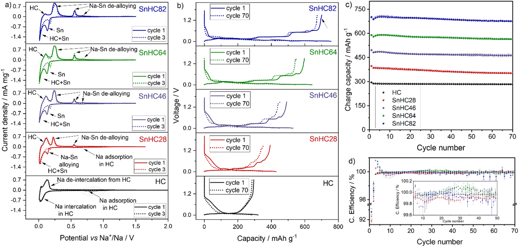 | ||
| Fig. 1 (a) Cyclic voltammograms at 0.1 mV s−1 for Sn/HC electrodes with different Sn:HC weight ratio. (b) Voltage profile during galvanostatic cycling at 50 mA g−1 (1st cycle) and 100 mA g−1 (70th cycle) and corresponding (c) cycling stability in terms of charge (de-sodiation) capacity and (d) coulombic efficiency. Tests conducted at 25 °C within the 0.01–1.5 V range. Electrolyte: 1 M NaPF6 in diglyme. | ||
Cyclic voltammetry was performed to investigate the electrochemical reactivity of HC and Sn during the de-sodiation process. Fig. 1a shows that all the Sn/HC electrodes exhibit two intense reduction peaks at ∼0.13 V and ∼0.01 V during the cathodic sweep, with intensities increasing with higher amount of Sn in the electrode underlining the alloying reaction between Sn and Na. The reduction peak at 0.01 V is detected for all Sn containing electrodes and similarly for the HC-based electrode, suggesting an overlapping reaction mechanism between Na–Sn alloying and HC–Na+ intercalation at very low potential values. Three anodic peaks located at 0.25 V, 0.55 V, and 0.68 V vs. Na+/Na indicate the reversibility of the Na–Sn de-alloying process20 with peak intensities increasing with Sn content.
A rather broad and flat cathodic peak is observed at ∼0.8 V for the HC-rich electrodes, i.e. HC and SnHC28, which can be correlated with Na+ adsorption into the HC structure (sloping region during galvanostatic cycling). An enlarged view of this peak is presented in Fig. S1a in the ESI.† In addition, all the electrodes show an anodic peak at ∼0.1 V during the de-sodiation corresponding to Na+ de-insertion from HC. The peak is more intense for electrodes with a high amount of HC, highlighting HC's contribution to the overall capacity. To further confirm the electrochemical reactivity of HC also in the Sn-rich electrodes, CV was performed on a SnC82 electrode where carbon black is used in a 20 wt% instead of HC. The results reported in Fig. S1b† show that the anodic peak at 0.1 V does not appear this time. However, an additional contribution at 0.15 V is observed which instead can be attributed to the de-insertion of Na+ from the amorphous carbon black matrix. This indicates that the carbon black still contributes to Na storage capacity, albeit to a much lower extent than HC.14
It is worth mentioning that an additional small broad anodic peak appears at ∼1.3 V during de-sodiation of Sn-rich electrodes. While this is not visible for the HC-rich electrodes in the data shown in Fig. 1a, a zoomed region is reported in Fig. S1c and d.† The peak appears to be irreversible (no corresponding cathodic peak) suggesting an ongoing irreversible oxidative process. This process is identified also in galvanostatic mode, especially for the SnHC82 electrode, as a small plateau appearing upon de-sodiation at about 1.3 V in the voltage profile (Fig. 1b). This feature has not previously been described in literature as the de-sodiation of Sn based anodes is generally reported up to 1 V. This plateau appears much reduced in the voltage profile of the same electrode (SnHC82) assembled in a Na half-cell and cycled with a carbonate-based electrolyte (reported in Fig. S2a†) highlighting a different reactivity of Sn with carbonate-based electrolytes when compared to glyme-based systems. In addition, Sn-rich electrodes exhibit initial lower OCV values (∼1.4 V) in diglyme compared to the same electrodes in EC:DEC (OCV > 2 V at the start of the first discharge curve in Fig. S2a†) and the pure HC electrode (OCV > 2 V in Fig. 1a), which may indicate a spontaneous chemical sodiation of Sn rich anodes in contact with diglyme-based electrolytes. This trend is clearly visible in Fig. 1a where the voltammogram for the first cycle starts at lower voltage for Sn-rich electrodes and is reflected also in galvanostatic mode (OCV value in the first discharge process in Fig. 1b). A low OCV in glyme-based electrolytes was also reported for other Sn-based electrodes.14,20 While the investigation of these differences is beyond the scope of the work presented, further studies are currently being undertaken to better understand the influence of ether-based systems in the sodiation mechanism of Sn anodes. After three cycles, the first cathodic peak at 0.13 V in Sn-based electrodes appears less intense and shifted to higher voltage (dotted line in Fig. 1a). This phenomenon was reported in previous studies20 and attributed to delayed sodiation and the SEI formation process in the initial cycle. However, the other redox processes are reproducible, revealing a good reversibility of the (de-)sodiation processes.
The cycling behaviour of the Sn/HC electrodes was tested galvanostatically with results reported in Fig. 1b–d. The voltage profiles of the Sn/HC electrodes compared to HC reveal the Na–Sn (de-)alloying mechanism, confirming the CV results. A clear contribution of HC is more visible for the SnHC28 material which presents a sloped voltage curve at higher voltages in both charge and discharge, indicating a rather limited contribution of Sn, which is instead observable with the appearance of voltage plateaus for higher Sn contents. As expected, the specific capacity increases by adding more Sn to the active material, transitioning from a minimum (upon de-sodiation) of 397 mA h g−1 for the SnHC28 electrodes (and 294.7 mA h g−1 for the pure HC electrodes) to a maximum of 701.5 mA h g−1 for the SnHC82. All electrodes show satisfactory cycling stability as reported in Fig. 1c, however a closer evaluation of the data reveals that unexpectedly the overall stability after 70 cycles does not decrease with a higher amount of Sn in the active material. On the contrary, the relative capacity retention as well as the first coulombic efficiency (FCE) value (Fig. 1d) improves with higher Sn content in the electrode composition. The delivered capacity, FCE and capacity retention for all the different types of electrodes are reported in Table 1.
| Electrodes | 1st de-sodiation capacity/mA h g−1 | FCE/% | 70th de-sodiation capacity/mA h g−1 | Capacity retention after 70 cycles/% |
|---|---|---|---|---|
| HC | 294.7 ± 0.2 | 91.9 ± 0.1 | 283.7 ± 0.2 | 96.2 |
| SnHC28 | 397 ± 4 | 91.9 ± 0.2 | 352.5 ± 0.2 | 88.8 |
| SnHC46 | 496 ± 4 | 92.3 ± 0.5 | 462 ± 10 | 93.3 |
| SnHC64 | 589.4 ± 0.1 | 92.7 ± 0.2 | 564 ± 5 | 95.7 |
| SnHC82 | 701.5 ± 0.1 | 92.8 ± 0.3 | 676.2 ± 0.8 | 96.4 |
As the volumetric expansion effects are expected to increase linearly with the amount of Sn in the electrode, and a large amount of HC should counter the volumetric expansion, the results reported here suggests a mismatch between the expected degradation mechanisms associated with volumetric expansion and the cycling stability of Sn-rich electrodes. Based on these findings, electrodes using Sn as the sole active material are expected to offer both high capacity and good stability, potentially outperforming the Sn/HC anodes investigated in this study. Notably, a recent study by Garayt et al.5 examined Sn-rich electrodes containing 80 wt% and 90 wt% micrometric Sn, combined with carbon black, SWCNT, PAA and CMC binder making up the remaining 20% and 10%, respectively. These electrodes demonstrated strong stability and delivered capacities exceeding 800 mA h g−1 when cycled in monoglyme at 30 °C. In terms of formulation, their 90% Sn electrode is equivalent to what would be considered a 100% Sn active material electrode in our system, as our formulations include 90% total active material. Interestingly, their results showed that increasing the Sn content from 80% to 90% led to only a marginal gain in capacity but reduced the capacity retention. This suggests that using 100% of Sn as the active material could offer slightly higher capacity at the cost of reduced cycling stability. However, due to significant differences in electrode formulation (particularly the use of different binders and conductive additives) a direct comparison between the two studies is not possible. Further investigation is therefore necessary to fully assess the cycling behaviour of Sn-only electrodes, which is currently ongoing in our lab.
To assess the role of HC in the cycling stability, a model electrode was prepared by using 80% of Sn and 20% of carbon black (C45) replacing the HC in the active material formulation (referred as SnC82) and tested under the same conditions. In this work, carbon black is considered as an active material for a better comparison with SnHC82 electrodes. A theoretical capacity of 180 mA h g−1 was accounted for as contribution from carbon black, in line with previously reported data for carbon black-based electrodes cycled in ether-based electrolytes.14 These electrodes exhibited a slightly lower capacity (first de-sodiation capacity of ∼660 mA h g−1) compared to the analogous SnHC82 and a shorter cycle life (see Fig. S3†). Indeed, the SnC82 electrodes assembled into Na half-cells presented a lower capacity and FCE, which can be ascribed to the higher surface area of the nanometric carbon black particles compared to the micrometric HC – most likely increasing reactivity with the electrolyte and leading to faster Na+ consumption. Possible agglomeration of the nanoparticles or poor mixing during electrode preparation due to the significant variation in particle size of μ-Sn and carbon black cannot be excluded. This result suggests that the use of HC instead of other carbon matrices impacts not only the capacity but also the long-term stability of Sn-rich composite electrodes, confirming the initial hypothesis of using HC as an active matrix to improve cycling stability. By contrast, Zhang et al.14 reported excellent cycle life and high capacity for electrodes fabricated with 20% of carbon black and 80% of μ-Sn in the active material when cycled in diglyme. However, the use of a higher wt% of CMC binder in their formulation can affect the long cycling stability, and the delivered capacity can vary if the carbon black is considered part of the active material, as it is in the present study. Thus, an optimisation of the composition and mixing procedure of the SnC82 electrodes could lead to improved performance. However, for the scope of this study, a better comparison between the two electrode types (SnHC82 and SnC82) was achieved by using the same conditions. All electrodes exhibit CE values ranging 99.8–101% except for the first and second cycle. Surprisingly the FCE of HC-rich electrodes is lower than the Sn-rich ones which are expected to exhibit lower reversibility due to the issues associated to the volume expansion of Sn upon sodiation, Na+ trapping and electrolyte consumption during SEI formation.25 The SnHC28 electrodes present the lower CE at every cycle while the pure HC electrodes show a consistent CE (∼100%) during all their cycling life. The anodes with >20% of Sn in the active material exhibit CE higher than 100 for cycle 3–6. This can be linked to the initial capacity hump reported for Sn-based anodes that might be associated to Na+ trapping in the very first cycle. The trapped Na+ can be released during the following cycles due to the favourable structural rearrangement of μ-Sn particles.5 A CE slightly above 100% is also observed for SnHC46 and SnHC64 electrodes from cycle 20 to 40 possibly indicating further a Na+ trapping and releasing processes in the electrodes, hence continuous rearrangement even after the initial first cycles. All electrodes show remarkable CE values considering that these are Na half-cell results, demonstrating adaptability of these anodes for full-cell application. The SnHC82 electrodes show a consistent CE until cycle 55, when the values start to deviate from the trend. Cycling all the electrode types at the same current density implies that those with higher amount of Sn will take more time to complete the same number of cycles when compared to those with less Sn since they deliver a higher capacity. Indeed, when calculating the theoretical specific capacities for the Sn/HC materials, the relative ratios for Sn and HC were taken into account. As an example, the theoretical capacity for SnHC82 and SnHC28 is calculated to be 707 and 394 mA h g−1, respectively, therefore a current density of 50 mA g−1 will correspond to a C-rate of ∼C/15 for the former and ∼C/8 for the latter (the calculation of the theoretical capacity for all Sn/HC materials is reported in the ESI†). As such, while the cycling stability is evaluated considering the number of cycles, which is the same for all the electrodes, the actual duration of electrochemical cycling is longer for Sn-rich anodes. The extended cycling time can lead to other forms of degradation including a pronounced electrode/electrolyte reactivity upon slower cycling but also degradation of other components of the cell such as electrolyte drying or separator breakdown.26,27
Rate capability tests were also performed to evaluate the influence of Sn addition in HC electrodes, which generally suffer from poor rate performance. The results reported in Fig. S4† (cycling test) and Fig. S5† (voltage profiles), show that addition of Sn to the electrode improves the rate performance, particularly at faster C-rate, due to the higher electronic conductivity of Sn compared to HC. In addition, the capacity is restored for all the electrodes after going back to lower C-rate. The electrochemical evaluation of the Sn/HC electrodes confirms that HC contributes to the electrodes' capacity proportionally to the percentage in the active material formulation, while the cycling stability of the anodes does not seem to improve when more HC is added to the active material and is reduced when carbon black is used instead of HC. The best capacity retention after 70 cycles is obtained by the SnHC82 electrodes, the electrode type with lower amount of HC in the active material, hence the one expected to be most unstable if considering a linear volumetric expansion with an increased amount of Sn. However, electrodes prepared by substituting HC with carbon black show a cycle life of only about 30 cycles highlighting a more effective stabilization effect of the HC compared to carbon black.
For comparison, the stable SnHC82 anode was also tested using a carbonate-based electrolyte to assess the effect of the electrolyte on the sodiation mechanism. A similar first (de-)sodiation is observed, suggesting that the (de-)alloying process of Na with Sn (at least in its first cycle) is rather independent of the solvent used during the first cycle. Indeed, the voltage profile reported in Fig. S2,† matches the profile observed when using glyme-based solvent. However, a low FCE (78.0 ± 0.3% compared to the 92.8 ± 0.3% observed for the same electrode in diglyme) and short cycle life indicates a high Na+ consumption during the SEI formation and suggests Na trapping in the electrode bulk leading to a fast cell failure. The poor performance of Sn-based anodes in carbonate electrolytes is well reported in the literature and attributed to the high reactivity of carbonate-based solvent with metallic Sn causing the formation of a thick and unstable SEI layer.20,21,28
In summary, the Sn-rich/HC electrodes (SnHC82) deliver the highest capacity and present the best capacity retention upon cycling with diglyme electrolyte. According to the predicted volume expansion of Sn, greater amount of it in the electrode would lead to increased volumetric expansion upon cycling, causing more pronounced bulk degradation such as cracking and eventual delamination. However, a clear mismatch between the predicted deleterious effects associated to volumetric expansion of Sn-based anodes and the improved cycling stability is observed in this study. To elucidate the discrepancy, ex situ analysis of Sn-rich electrodes was carried out to understand the origins of their stability and will be discussed in Section 3.3.
3.2 Particle size effect on the Na–Sn alloying process
To assess how particle size affects the Na storage behaviour of Sn, two other Sn powders (sub-micrometric and nanometric) were electrochemically investigated after mixing it with HC.A comparative structural and morphological characterization of the different Sn powders employed in this work is presented in Fig. S6.†
The XRD patterns reported in Fig. S6a† reveal that all Sn powders exhibit the tetragonal (I41/amd) β-Sn phase, which is the most stable Sn crystalline phase at room temperature. The presence of tin oxide (SnO, P4/nmm) was detected only for the nanometric-Sn powder as evidenced by the appearance of the peaks at ∼29.6°, 33.0°, 36.8°, 47.6°, 50.4° and 57.1°, probably due to the higher surface/volume ratio of nanosized particles.29,30 The similar full width at half maximum (FWHM) values revealed by the peak analysis (Table S1†) highlight that the crystallinity of the different Sn powders is comparable. The SEM images in Fig. S6b† show that all three samples exhibit spherical-like particles with a broad size distribution. The SEM micrographs were analysed by using the program ImageJ, with results reported in Fig. S6c.†. The micrometric powder exhibits particle sizes ranging from ∼1 to 45 μm with majority in the range of 15 μm; the sub-micrometric Sn shows particles with size ranging from ∼0.5 to 7 μm, and the nanometric Sn is mostly composed of 10–400 nm size particles.
To assess their electrochemical performance, Sn/HC electrodes were prepared using the sub-micrometric and nanometric Sn. A Sn/HC ratio of 8/2 was chosen based on the good cycling stability and high capacity observed for μ-Sn/HC anodes in Section 3.1.
The decrease in size of Sn particles is expected to improve cycling stability owing to the increased resistance to stress-induced damages caused by the volume expansion during the alloying process. However, Fig. 2 shows the poorer performance of submicrometric and nanometric Sn-based anodes when compared to electrodes made with the larger micrometric Sn particles. Both the submicrometric and nanometric Sn electrodes show lower FCE, capacity and cycling stability. The voltage profiles of the electrodes prepared with Sn materials of different sizes appear substantially different. The voltage profile during the first sodiation for the μ-Sn/HC electrode exhibits only three voltage plateaus (at ∼0.2 (IDC), 0.08 (IIDC)and 0.03 V (IIIDC)) and four well-defined plateaus upon de-sodiation (at ∼0.14 (ICC), 0.27 (IICC), 0.52 (IIICC), 0.62 V (IVCC)) with the addition of a small plateau at ∼1.3 V discussed in the previous section. Upon further cycling, during the following sodiation (10th cycle) an additional plateau is observed at ∼0.3 V (indicated with an asterisk (*) in Fig. 2) contributing to a full reversibility of the de-sodiation process with four steps as previously reported by Ellis et al.31
 | ||
| Fig. 2 Galvanostatic cycling of micro-, submicro- and nano-Sn/HC electrodes (8:2 wt%) cycled at 50 mA g−1 (1st cycle) and at 100 mA g−1 (10th cycle). Tests conducted at 25 °C within the 0.01–1.5 V range. Electrolyte: 1 M NaPF6 in diglyme. | ||
The voltage profile of the sub-micrometric Sn anode shows all the four plateaus typical of Sn at the first sodiation and exhibit shortened plateaus upon charge with a slopy curve at the end which resembles the HC voltage profile. This suggests a loss of activity of the Sn particles which agrees well with the following sodiation profile presenting only two plateaus, a small one at ∼0.3 V and a longer one at voltage below 0.08 V. At the end of the first sodiation the plateau at ∼1.3 V appears longer than the μ-Sn/HC case indicating a possible increase in reactivity with the electrolyte when smaller particles with higher surface area are used. The following cycles show only two plateaus in discharge and charge and consistently low capacity, indicating Na+ trapping and loss of active material. The absence of the plateau at ∼0.3 V during the first sodiation in the μ-Sn voltage profile, which is visible for the sub-micrometric Sn electrode, can be ascribed to the larger particle size of the former and was reported in the literature for other micrometric Sn electrodes.5,14 A similar phenomenon is also described for micrometric Sn particles and foil used as anodes for LIBs that exhibit one discharge plateau at low voltage for the first cycle and three for the following cycles.32 Zhou et al.33 justify this effect considering the improved Li+ diffusivity in Li-rich phases compared to Li-poor phases which favoured the formation of the former during the first cycle, leading to the presence of a single plateau. This effect is intensified when the particle size is larger due to the lower surface exposed, making the particles experience a higher current density compared to the smaller ones. For this reason, the other plateaus appear at the following cycles after the breakdown of the large particles. However, as will be shown later in this study, operando XRD of μ-Sn-based electrodes indicate the appearance of the Na/Sn phase formed during the first plateau even when this is not present in the voltage profile during the discharge (see Fig. 6b in Section 3.3 and Fig. 9a in Section 3.4). This suggests that in the Na/Sn system the absence of the first plateau during the first sodiation of μ-Sn particles can be ascribed to polarization effects being intensified in the larger particles due to the higher concentration gradient experienced during Na+ insertion, that decreases for the subsequent cycles following the particle size reduction.34 A different voltage profile is observed for nanometric Sn, which suggests the reactivity of SnO and Na through a conversion mechanism, as indicated by the plateau at ∼0.4 V upon sodiation and the sloped plateau starting at ∼0.8 V upon de-sodiation.29 The presence of SnO in the nanometric Sn powder was indeed detected by XRD (Fig. S6a†). While SnO2 is expected to be the thermodynamically stable phase at room temperature, Sutter et. al.35 reported the formation of an amorphous Sn oxide layer with stoichiometry Sn:O (1:1) growing on the surface of Sn nanoparticles (from 2–3 to 100 nm) at room temperature. In this study, the presence of an amorphous phase cannot be completely excluded, however the SnO layer covering the surface appears to have a degree of crystallinity as observed from the XRD pattern in Fig. S6a.†
In summary, μ-Sn/HC show improved performance revealing an increased Na storage ability when compared to sub-micrometric and nanometric Sn/HC electrodes. However, the stable cycling seems to occur only when the electrode is cycled in diglyme and not in a carbonate-based electrolyte (EC:DEC) as showed in Fig. S2.† There is still much debate on the role played by the glyme-based electrolyte in ensuring the stability of μ-Sn-based anodes but a common agreement seems to reside on the higher stability of glyme-based solvent toward metallic Sn reactivity compared to the carbonate-based solvents, which favours the formation of a thin, polymeric and elastic SEI layer.20,21,28 The effect of the particle size on electrode stability can be rationalized by considering the formation of what is commonly referred to in the literature as bicontinuous nanostructure which may be responsible for the cycling stability of Sn anodes. This structure emerges during the “selective dissolution”36 (or de-alloying) of one component in certain alloy system, such as Ag–Au, Li–Sn, Li–Pb, Li–Bi,19 and more recently, Na–Sn system.37 This process results in the formation of a unique structure composed by the metal component (i.e. Sn, Bi, Pb, etc.) which closely resembles a coral-like morphology. Such structures have been observed for various Sn-based anodes after cycling in Na cells using glyme-based electrolytes after continuous (de-)alloying processes.17,18 The resulting bicontinuous network consists of elongated particle (ligaments) of the metal interconnected in a porous, coral-branch-like framework. Sieradzki et. al.19 studied the Li–Sn alloy system and identified a number of parameters that influence the formation of the bicontinuous structure. These include the alloy composition, the particle size, the current density experienced by the particles during de-alloying and the SEI stability. In particular, they identified a critical particle size of 300 nm, below which the porous structure does not develop for Sn and observed that small particles (<8 μm) tend to form thinner ligaments which are unable to coalesce and form a dense, coral-like bicontinuous network. They attributed the origin of the phenomenon to the high stability of the SEI in smaller particles, which inhibits the coarsening of the ligaments during the de-lithiation. Thus, it may infer that the formation of the bicontinuous structure is not achieved when using sub-micrometric and nanometric Sn, contributing to the inferior cycling stability when compared to μ-Sn. In addition, Shen et al.37 demonstrated that the morphology of Sn particles varies depending on the pre-sodiation/pre-lithiation process and the solvent used during subsequent de-alloying, highlighting the significant role of the electrolyte in shaping the final structure. As will be detailed in the following sections, the development of the coral-like structure in μ-Sn-based electrodes may require multiple alloying/de-alloying cycles and specific cycling conditions to effectively occur illustrating that multiple factors can simultaneously influence the bicontinuous structure evolution of Sn particles during (de-)alloying.
3.3 Post-mortem study of μ-Sn-rich anodes
To understand the origin of the cycling stability observed for the μ-Sn rich electrodes (SnHC82 and SnHC64), post-mortem analysis was conducted to gain deeper insights into the structural and morphological changes occurring upon cycling. To examine the morphological evolution upon cycling and the potential development of a bicontinuous structure, cross-sectional SEM-EDS analysis was performed at selected de-sodiated states across different cycles. Fig. 3 reports the cross-section SEM and EDS analysis conducted on SnHC82 electrodes in the pristine state and after 1, 5, 25, and 70 cycles. | ||
| Fig. 3 Ion-beam milled SEM cross-sections with corresponding EDS for pristine SnHC82 electrodes and cycled electrodes (1st, 5th, 25th and 70th cycle in the de-sodiated state). | ||
In the pristine electrode, SEM images reveal clearly distinguishable regions of Sn (bright areas) and carbon (dark areas) distributed in the cross-section, also highlighted in green and red, respectively, in the EDS elemental maps. The high magnification image of the pristine electrode also evidences the presence of Sn particles up to 10 μm in size. It is worth noting that the morphology of the Sn particles appears altered by the calendering process carried out on the electrodes, as compared to the original morphology reported in the SEM image of the pristine powder as received (see Fig. S6b†). Moreover, SEM cross-section confirms that the thickness of the electrode is approximately 15 μm.
Following the first de-sodiation (cycle 1), significant morphological changes are observed. The electrode becomes thicker and more porous as a result of the structural reorganization and size reduction of Sn particles. These changes lead to the formation of large voids between particles and a bulging of the electrode surface, which no longer appears smooth and flat as in the pristine state. High magnification SEM image revealed the development of numerous pores of varying sizes within the bulk of the particles with edges appearing rough. The structural reorganization and morphological changes clearly revealed individual HC particles (flat-like dark particles). Continued cycling of the electrodes leads to the growth of coral-like structure,17,18 characterized by a network of elongated submicrometric Sn particles (ligaments). This network appears to nucleate from the individual micrometric Sn particles and then gradually expands throughout the electrode thickness upon cycling. Indeed, the SEM-EDS images of the electrode cycled for 5 cycles show isolated nuclei of the coral-like structure, while after 25 and 70 cycles, the Sn-network is widely distributed and extended across the whole electrode thickness. Although the surface of the anodes tested for longer than one cycle appears smooth, it displays small protrusions. In addition, Na (visible as a light purple signal in the EDS images) is detected on a thin surface layer of the cycled electrodes, which appears to thicken with continuous cycling. This signal is more apparent in the images where the beam is not perpendicular to the cross-section, as a larger portion of the surface is visible. The layer is also observed around certain particles within the electrode bulk, suggesting the formation of an SEI layer rich in Na-containing components. The SEM images also reveal that the overall electrode's thickness increases compared to the pristine state (∼20 μm). However, the overall volumetric variation (25% considering an initial thickness of 15 μm) is relatively small and does not align with the detrimental effects expected after the full sodiation/de-sodiation process of Sn. This discrepancy suggests that the reduction of Sn particle and their morphological restructuration into the coral-like structure contribute to the improved cycling stability observed for Sn-rich electrodes. It appears that Sn particles undergo a self-healing process after the initial de-sodiation, mitigating volumetric expansion effects and consequent particle cracking. This process is facilitated by the formation and growth of a porous Sn framework responsible for the structural integrity of the electrode. A similar morphology was previously reported for Li–Sn systems19 suggesting that a lithiation degree of more than 50% is necessary to obtain a bicontinuous structure after the complete de-alloying of Sn particles. Lower Li quantity in the particles only leads to void formation and surface roughening. A too slow de-alloying rate can also prevent the evolution of this structure, as previously reported for a Li/Sn system by Chen et al.19 This is most likely the case also for our Sn/HC system, as the coral-like structure is not clearly visible after the first cycle, which was conducted at a lower current density of 50 mA g−1, compared to 100 mA g−1 used in the subsequent cycles. Finally, the shape and dimension of the elongated submicrometric particles (ligaments) seem to be influenced by different parameters such as Sn particle size and type of electrolyte used, which can attenuate the coarsening of the ligaments. Specifically, the evolution of a bicontinuous network is not reported for nanometric Sn particles, while Li alloying/de-alloying of submicrometric Sn particles results in the formation of nanosized ligaments. The ligament diameter increases for Sn particles of 10–50 μm, reaching values up to 1–2 μm,19 similar to the ones observed in our electrode.19 In addition, the formation of Kirkendall voids, such as the ones appearing in the particle after the first de-sodiation and in some of the Sn ligaments after long cycling can be a consequence of unequal diffusion rates of Na+ from different Sn particles during the de-alloying mechanism, probably influenced by the crystallinity of the particles.38
The same analysis was carried out on SnHC64 electrodes (Fig. 4), where the μ-Sn particles constitute 60 wt% of the active material.
 | ||
| Fig. 4 Ion-beam milled SEM cross-sections with corresponding EDS for pristine SnHC64 electrodes and cycled electrodes (1st, 5th, 25th and 70th cycle in the de-sodiated state). | ||
These electrodes, despite showing satisfactory long-term cycling stability, exhibited slightly lower capacity retention compared to the SnHC82 electrodes (see Table 1). Cross-sectional SEM-EDS analysis was carried out to identify morphological differences upon cycling compared to the SnHC82 electrode, aiming to identify potential degradation pathways not observed for the Sn-rich anodes.
The SEM images illustrated the evolution from a smooth pristine electrode to a more porous and thicker structure following the first de-sodiation. By the end of the 5th cycle, small nuclei of coral-like structure begin to form, though more sparsely distributed than in the SnHC82 electrode, likely due to the lower Sn content. After 25 and 70 cycles, the morphology of the SnHC64 electrodes show clear differences from the SnHC82 ones extracted at the same cycle. The Sn network formed during cycling does not extend uniformly across the electrode thickness; instead, the isolated coral-like clusters remained along with nanometric Sn particles dispersed throughout the electrode. The elongated Sn particles forming the coral-like structure appear thinner and less dense compared to those in the SnHC82 electrode after 70 cycles.
A light purple signal from Na can be detected on the surface of the cycled electrodes and around the particles indicating again the growth of a passivation layer during cycling mostly composed of Na components.
The different morphology for the two types of Sn-rich anodes can be attributed to the different concentrations of Sn in the electrodes. The higher amount of Sn in the SnHC82 anodes allows the formation of an extended network of interconnected elongated sub-micrometric Sn particles. In contrast, when the concentration of Sn in the active material is lower (60%), the elongated particles formed upon cycling are not close enough to connect and create an extended coral-like structure. Instead, their size appears reduced, and greater porosity develops within the bulk of the electrode, leading to a larger volumetric expansion after 70 cycles. As a result, the SnHC64 electrode is thicker than the SnHC82 after 70 cycles. The different extension of the coral-like structure in the SnHC82 and SnHC64 electrodes is confirmed by XCT analysis of the two de-sodiated electrodes cycled for 25 cycles. The XCT 3D reconstruction of the pristine and cycled SnHC82 and SnHC64 electrode, is reported in Fig. 5a and in Fig. 5b, respectively.
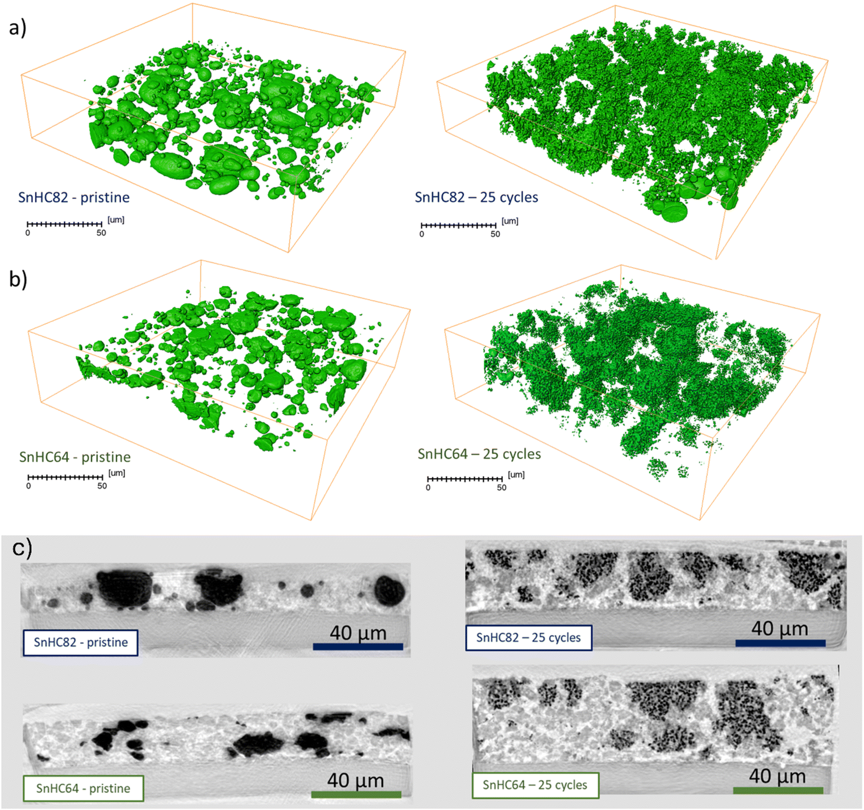 | ||
| Fig. 5 Observation of the spatial distribution of Sn particles from phase contrast XCT of a 150 μm wide, 150 μm deep area of the pristine and cycled (a) SnHC82 and (b) SnHC64 electrodes (100 nm resolution images). (c) Orthogonal slice views of the SnHC82 and SnHC64 pristine and cycled electrodes. | ||
The tomographies have been obtained by segmenting Sn from the rest of the electrode to observe the spatial distribution in 3D. A comparison of pristine uncycled SnHC82 and SnHC64 electrodes show a lower amount of Sn within the investigated volume as expected. In addition, the images reveal a less dense coral-like Sn network for the SnHC64 compared to the SnHC82 anode in their cycled states. The SnHC64 electrodes also presents some small, isolated coral-like nuclei and Sn nanoparticles scattered in the electrode which are not merged in bicontinuous dense framework as much as in the SnHC82 electrode. As previously mentioned, the efficiency of the Sn ligaments coarsening process significantly impacts their properties and size, which in turns affects the formation of a robust bicontinuous porous structure.
The side view of the two electrodes (Fig. 5c) reveals a greater increase in thickness for the SnHC64 electrodes. The average thickness was calculated measuring approximately 20 points of the 100 nm resolution scans. For the SnHC64 pristine electrode this corresponds to 20.99 ± 0.88 μm, while the cycled electrode measures 39.37 ± 1.43 μm, equivalent to a 46.6% increase in thickness. In comparison, the SnHC82 electrode exhibit a smaller thickness increase, with the pristine electrode averaging 16.5 ± 1.8 μm and the cycled one 24.19 ± 2.05 μm, corresponding to a 31.8% increase. This greater thickness increase in the SnHC64 electrodes occurs despite the lower amount of Sn in the active material, which is likely responsible for the volume expansion. The particle volume distribution for the pristine and cycled SnHC82 and SnHC64 electrodes, calculated from images obtained at a 30 nm resolution, is shown in Fig. S7.† The analysis reveals a significant reduction in Sn particle size from the uncycled electrodes to those extracted after 25 cycles for both samples. Specifically, while the particle volume in the pristine electrodes mostly falls within the 1–10 μm3 range, with some large and small particles, the cycled electrodes show nearly 100% of the particles in the 0–0.1 μm3 range.
This analysis shows that the extension of the Sn network through the electrode proceeds slower for the SnHC64 compared to the SnHC82 electrodes. In the SnHC64 cycled samples, the coral-like clusters are physically separated during their initial formation, and the ligaments are smaller, preventing them from merging. However, the compactness of the SnHC64 electrode improves during cycling, even without the growth of a thick Sn network. It is important to note that the higher amount of HC in the SnHC64 electrode likely contributes to better structural stability independently from Sn's behaviour. Since the SnHC82 electrode outperformed the other electrodes despite the higher amount of Sn, hence the larger volume expansion, it is inferred that the growth of an extended coral-like structure constituted by sub-micrometric (smaller than pristine) Sn particles plays a crucial role in the stabilization of Sn-rich electrodes, thus explaining the mismatch between the detrimental effects associated with the predicted volumetric expansion and the observed cycling stability.
To further investigate the reversibility of the structural changes accompanying the morphological reorganization of Sn upon de-alloying, ex situ XRD was carried out on the SnHC82 cycled electrodes. The XRD patterns of the pristine and cycled electrodes (cycle 1, 5, 25, and 70) are reported in Fig. 6a.
 | ||
| Fig. 6 (a) Ex situ XRD patterns of SnHC82 electrodes in the pristine and cycled states. (b) Operando XRD over ten cycles of the SnHC82 electrode cycled at 50 mA g−1 (1st cycle) and at 100 mA g−1 (10th cycle) in Na half-cell using 1 M NaPF6 in diglyme as electrolyte. | ||
The XRD pattern of the pristine SnHC82 electrode exhibits the β-Sn peaks and an additional small peak arising from the aluminium current collector at ∼38.5° (indicated by the dotted vertical line in Fig. 6a and used as a reference for peak shifting). The broad flat peak at lower degrees values is attributed to the kapton tape used to avoid air contact with the samples during the measurement (see Fig. S8† confirming kapton tape contribution and excluding a HC signal likely due to the low quantity in the electrode formulation). Upon sodiation, after cycling up to 0.01 V, the XRD pattern (red curve), matches with the Na15Sn4 structure corresponding to the fully sodiated Sn phase. Na15Sn4 is the only sodiated phase forming during cycling which corresponds to a thermodynamically stable Na/Sn phase.31,39 Following the first de-sodiation, intense β-Sn peaks reappear in the XRD pattern, confirming a high degree of reversibility of the (de-)alloying reaction. A detailed examination of the main Sn peaks reveals peak broadening as the cycling progresses from pristine to longer cycled electrodes, which can be attributed to a lower degree of crystallinity in the Sn particles undergoing continuous de-sodiation or to the reduction in particle size during the formation of the coral-like structure. Overall, these results confirm the good reversibility of the process, as indicated by the high CE observed in the electrochemical tests. The high reversibility is further confirmed by the operando XRD of the SnHC82 electrodes cycled in 1 M NaPF6 in diglyme for 10 cycles which reports the same phase transitions at every cycle and the Sn peaks at the end of every charge, independently on the current density employed, i.e. 1st cycle at 50 mA g−1 and following cycles at 100 mA g−1 (see Fig. 6b).
Other unidentified small peaks are observed in the ex situ XRD pattern of the de-sodiated sample at 11.8°, 16.4°, 28.7°, 33.2°, 35.6°, which may correspond to unknown Sn/Na phases formed during sodiation, suggesting Na+ trapping within the anode. However, a comparison of the XRD pattern with known crystalline phases formed during the de-sodiation of Sn show no direct correlation with any established phase. After further cycling, some of these peaks disappear, but others retain small contributions at different angles. Wang et al.40 reported on the growth of a crystalline organic SEI component on various anode materials cycled in diglyme including Sn and HC. Their work highlighted the appearance of crystalline peaks at 9.1° and 18.2° in the XRD pattern of electrodes cycled with NaCF3SO3 in diglyme, which they attributed to the crystallisation of a complex composed by diglyme molecules, Na+ and the salt anions (triflate). Although the peaks observed in the presented XRD pattern do not match exactly those reported by Wang et al.40 some of them fall in the same theta range (11.8° and 16.4° instead of 9.1° and 18.2°) indicating a possible correlation. Indeed, it is worth noting that, in this study NaPF6 is used as salt instead of NaCF3SO3, potentially explaining the slightly different theta values due to their different structure. However, further studies and analysis are needed to fully identify these contributions.
3.4 Investigating cycling stability of Sn/HC anodes in full cells
Full-cells were assembled in coin-cell format to better assess the electrochemical behaviour of Sn/HC anodes under practical cell operating conditions. The investigation focused on the SnHC82 and the SnHC28 anodes, with results compared to the standard HC containing full cells, all using PW as the cathode material. The cycling data for the full-cells are reported in Fig. 7. | ||
| Fig. 7 (a) Voltage profile of the full-cells made with SnHC82, SnHC28 and HC as anodes and PW as cathode with an N/P of 1.1 during galvanostatic cycling at 50 mA g−1 (1st cycle) and 100 mA g−1 (2nd and 50th cycle). Corresponding (b) cycling stability in terms of discharge capacity and (c) coulombic efficiency. (d) Calculated gravimetric and volumetric energy density (1st cycle) for the three cells. The results are reported per kg L−1 of active materials (anode + cathode). Tests conducted at 25 °C within the 1.3–3.8 V range. Electrolyte: 1 M NaPF6 in diglyme. | ||
All three cells delivered a comparable first charge capacity (∼150 mA h gcathode−1) and a corresponding discharge capacity of about 127, 124 and 119 mA h g−1 for the HC, SnHC28 and the SnHC82 containing cells, respectively. The SnHC82|PW cell exhibiting the lower FCE, likely due to more significant SEI formation during the initial cycle (see voltage profile in Fig. 7a). Notably, none of the anodes had undergone any pre-sodiation process. By increasing Sn content, the voltage profiles of the full cells exhibit the typical features characteristics of the Na–Sn alloying process, with plateaus especially observable during the discharge process in contrast to the more slopy profile observed for the HC containing full cell.
Although both Sn-containing electrodes demonstrated satisfactory stability when tested in Na half-cells, the Sn-rich electrode show poorer performances in full-cell configuration. After 100 cycles the Sn-rich anode maintained only 82% of its initial discharge capacity, lower than the 88% and 84% retention observed for the HC and SnHC28 anodes, respectively as reported in Fig. 7b. The CE reported in Fig. 7c declines earlier for the SnHC82|PW full cell (from around cycle 20) and remained lower than the other two systems throughout the rest of the cycling. The fast capacity fading and lower CE trend for the SnHC82|PW full cell may originate from Na+ being trapped within the SnHC82 anode, leading to a fast depletion of active Na over prolonged cycling. This could explain why SnHC82 maintains better cyclability in half-cells, where Na metal used as a counter electrode serves as an infinite source of Na+.
Considering the high reversibility of the Na–Sn de-alloying process confirmed by the XRD of the SnHC82 electrodes cycled in half-cells (Fig. 6), the faster capacity fading in full-cells may stem from Na+ retention on the surface of the electrode as part of the SEI components, highlighting the importance of understanding the phenomena occurring at the electrode/electrolyte interface.
The gravimetric and volumetric energy density of the three cells during the first cycle are reported in Fig. 7d. Volumetric energy densities were calculated using the theoretical densities of Sn, HC and PW, which are 7.3 g cm−3, 1.6 g cm−3, and 2.2 g cm−3, respectively. The results are reported per weight/volume of total active materials (anode + cathode) with other cell components not included in the calculation. Although the full cells containing Sn/HC electrodes exhibit inferior cycling stability, the incorporation of 80% or 20% of Sn in the active material results in enhancements of about 18% (272 W h kg−1) and 10% (252 W h kg−1) respectively, in gravimetric energy density relative to the cells using pure HC electrodes (230 W h kg−1). Moreover, owing to the intrinsically higher density of Sn, the volumetric energy density is significantly improved by the addition of Sn. An increase of 56% in volumetric energy density is achieved using SnHC82 anode (689 W h L−1 compared to the 443 W h L−1 obtained with pure HC anodes), while a 30% increase is gained when 20% of Sn is added to the active material (577 W h L−1). However, it is noteworthy that a fourfold increase in Sn content (wt%) (comparing SnHC82 to SnHC28) results in only a twofold increase in volumetric capacity, suggesting only a partial utilization of Sn during cycling.
To elucidate the Na–Sn alloying reaction path in full-cells, three-electrode cells were assembled using Na as the reference electrode, allowing independent monitoring of the voltage profile of both anode and cathode during cell operation.
The results, reported in Fig. 8b, reveal that the Sn/HC anodes do not reach the lower cut-off voltage of 0.01 V in the full-cell configuration. Instead, the SnHC82 anode stop at about 0.04 V and the SnHC28 anode achieved a slightly lower cut off voltage of 0.03 V, right above the potential needed for the fourth discharge plateau to appear (as seen for half-cell data in Fig. 1b). Thus, the full capacity obtained by the Sn containing anodes cannot be achieved in full-cell configuration. The specific capacity per gram of anode material in both half- and full-cell configuration is reported in Fig. 8a. In agreement with the three-electrode cells data, the SnHC82 anode in full-cell achieves a capacity of 450 mA h g−1, significantly lower than the 700 mA h g−1 observed in half-cell. This latter value corresponds to the capacity reached at the 3rd plateau in the voltage profile of the SnHC82 in half-cell (blue curve in Fig. 1b). To further validate the partial sodiation of Sn anodes in full-cell, ex situ XRD was carried out on the Sn anode recovered after the first charge in full-cell. As shown in Fig. 8c, the XRD pattern of the Sn anode cycled in full-cell differs significantly from that of the same anode obtained after a complete sodiation in half-cell (red pattern in Fig. 6a). In fact, the latter matches with the fully sodiated Na15Sn4 phase obtained at the end of the 4th plateau, while the anode recovered from the full-cell appears to be a mixture of multiple crystalline phases. The dominant phase corresponds to the metastable hexagonal (R-3m) Na5Sn2 phase, as previously computationally predicted by Baggetto et al.39 for the phase forming during the third discharge plateau. An equivalent XRD pattern has also been reported by Ellis et al.,31 who associated it with the phase forming in the third plateau, which deviates from the thermodynamically stable Na9Sn4 phase expected at that Na concentration. Additional peaks are attributable to residual metallic Sn and minor amounts of Na15Sn4.
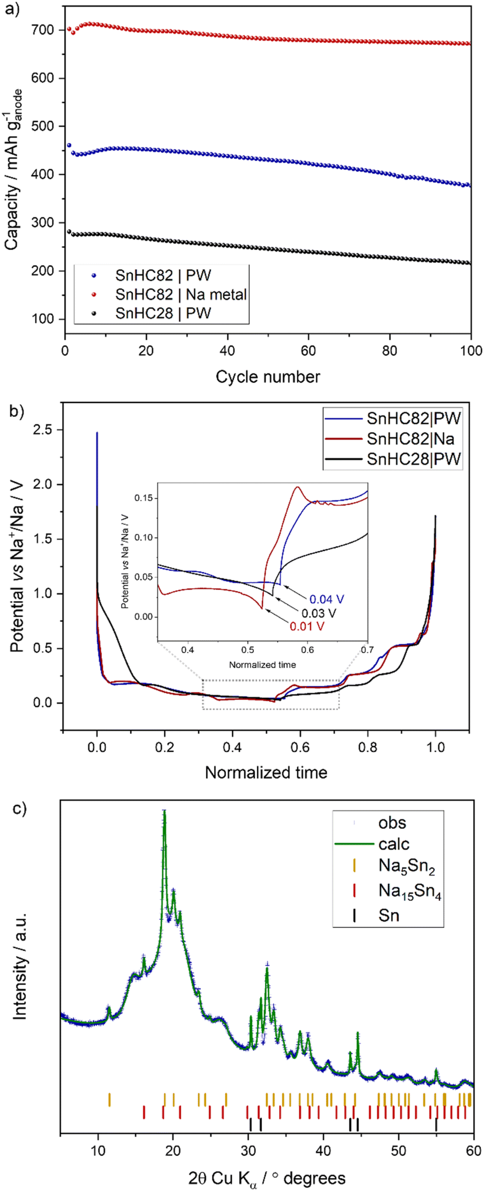 | ||
| Fig. 8 (a) Charge capacity per grams of anode for SnHC82 and SnHC28 cycled in full-cells containing PW cathode (N/P of 1.1) and for SnHC82 cycled in Na half-cell. (b) First cycle anode voltage profile for SnHC82 and SnHC28 in full cells (obtained from three electrodes cell test) with PW as cathode and SnHC82 in half-cell (coin cell). (c) Ex situ XRD of the SnHC82 electrode extracted from the full-cell after a full charge (sodiation) at 50 mA g−1. | ||
To further confirm the uncompleted sodiation of the Sn-rich anodes in full-cell configuration, operando XRD measurements were carried out on the SnHC82 electrodes during cycling in both full- and half-cell. Such experimental technique allows continuous monitoring of phase evolutions within the electrode materials during (de-)sodiation, avoiding relaxation and potential contamination induced by post-mortem analysis.
Fig. 9a displays the contour plot for the first (de-)sodiation cycle of the SnHC82 electrode cycled in half-cell (extracted from the full experiment reported in Fig. 6b). Four distinct phase transitions occurring upon sodiation are clearly identified by the appearance and disappearance of specific diffraction peaks. The initial transition from β-Sn to a crystalline intermediate with an approximate stoichiometry of Na0.6Sn occurs around 0.2 V, evidenced by the fading of Sn peaks at 14.0°, 14.6°, and the emergence of new reflections at 8.9°, 12.7°, 15.5°. This phase transition correlates with the first plateau in the discharge voltage profile which, as discussed in the previous sections, is not prominently observed in the first cycle of μ-Sn electrodes. While the first plateau is similarly subdued in the voltage profile of the operando cell, the emergence of the Na0.6Sn phase onset of discharge suggests electrode polarization. The sodiation process proceeds with the formation of an amorphous NaSn phase, followed by crystalline Na5Sn2 (with characteristic peaks at 8.8°, 9.4°, 15.1° and 15.5°) and finally the fully sodiated crystalline Na15Sn4 phase with peaks at 7.5°, 8.7°, 9.8°,14.6°,15.2° and 15.8°. The following de-sodiation proceeds largely as the reverse of these transitions, except that the initial Na0.6Sn crystalline phase is not recovered during the last charge plateau and is instead replaced by an amorphous phase. These observations are consistent with previous operando studies conducted on Sn-based anodes.14,31
 | ||
| Fig. 9 (a) Operando XRD during the 1st (de-)alloying process for the SnHC82 electrode cycled in half-cell at 50 mA g−1 within the 0.01–1 V voltage range. The first cycle data are extracted from the full (10 cycles) experiment previously reported in Fig. 6b. (b) Operando XRD during the 1st cycle of the SnHC82 electrode cycled in full-cell with PW as the cathode. Test conducted at 50 mA gcathode−1 within the 1.3–3.8 V voltage range. Ion-beam milled SEM cross-sections image of the SnHC82 electrode cycled in (c) half-cell and (d) full-cell for 100 cycles. | ||
A similar mechanism is presented for the SnHC82 anode cycled in full-cell (Fig. 9b). However, the final phase transition during charging, corresponding to the sodiation of the Sn anode, does not culminate with a complete conversion of the Na5Sn2 into the Na15Sn4 phase. Indeed, a mixed phase composition is evident, resembling the ex situ XRD pattern previously shown in Fig. 8c. Additional reflections corresponding to the PW cathode used in the full-cell are indicated with asterisks (*). The incomplete sodiation of the Sn anode in full-cell configuration, as revealed by operando XRD, aligns well with the three-electrodes cell data (Fig. 8b), which indicate that the anode potential does not get below 0.04 V during charging. This voltage limitation prevents the formation of the final Na15Sn4 fully sodiated phase.
Cross-sectional FIB/SEM analysis was conducted to examine the impact of the partial sodiation of Sn observed in full-cells on the electrode morphology. SnHC82 anodes were recovered from both half- and full-cells after 100 charge/discharge cycles and prepared for FIB milling and SEM imaging. The corresponding cross-sectional SEM micrographs are reported in Fig. 9c and d, while 3D FIB-SEM video reconstruction of the electrode morphology is provided in the ESI.†
The microstructural evolution of the Sn network formed during cycling differs significantly between the cell environments (half- vs. full-cell), particularly in terms of overall compactness of the electrode. In full-cells, Sn particles retain a coral-like structure, yet the ligaments appear noticeably thinner and less interconnected. In addition, the discrete nature of the coral-like clusters seems to induce mechanical degradation, manifesting as electrode cracking in their vicinity. Notably, the persistence of metallic Sn cores within some particles suggests incomplete sodiation even after 100 cycles.
The different morphologies and microstructure can be attributed to the different degrees of sodiation experienced by Sn particles in half- and full-cell. This observation is consistent with the theory describing the emergence of bicontinuous structures during de-alloying processes, previously discussed and applicable to Li–Sn alloys.19 In fact, the shape and dimension of the ligaments within the coral-like structure may be affected by the initial alloy composition at the onset of the de-alloying process. In our study, Na15Sn4 is the predominant phase in half-cell cycled electrodes, whereas a mixed phase comprising Na5Sn2 and Na15Sn4 is detected in full-cell cycled electrodes. The inability to form a robust, thick, dense and interconnected coral-like structure in full-cell likely contributes to electrode cracking which, in turn, accelerate Na+ consumption via continuous electrolyte decomposition upon exposure of fresh electrode surfaces, leading to faster capacity fading. These results underscore the critical role of the self-healing behaviour intrinsic to the coral-like morphology in preserving structural integrity and cycling stability of Sn anodes.
This study suggests that the partial sodiation of Sn is the main cause for the faster capacity fading observed in full-cells when compared to half-cell data. Beyond compromising electrode stability, a partial sodiation certainly leads also to a decreased delivered capacity, and consequently a lower energy density of the cell. In order to achieve the full potential of Sn anodes in Na-ion cells, the development of a dense, thick, and interconnected coral-like structure is essential. This distinctive morphology can form and extend throughout the electrode only when a fully sodiated crystalline phase is achieved during sodiation. In our study, the voltage profile of the anode in full-cell configuration indicated an incomplete sodiation (see Fig. 8b and c). However, with further optimization of cell design or by changing the cathode material, it may be possible to attain the fully sodiated crystalline phase. This would, in turn, promote the formation and growth of the coral-like structure, which helps to mitigate the volumetric expansion typically expected based on theoretical models. As an initial step in optimization, the full-cell design was modified by adjusting the N/P ratio (see Fig. S9†).
Reducing the ratio from 1.1 to 0.97, effectively lowering the amount of anode, was intended to enhance anode sodiation. This adjustment resulted in improved capacity retention over cycling and a slight increase in anode capacity (510 mA h g−1 compared to the 450 mA h g−1 obtained with a 1.1 N/P).
Further improvements in cathode materials and additional design optimizations could lead to enhanced overall capacity and increased volumetric energy density of the cell.
Interestingly, while other alloying systems (e.g. Li with Si) may benefit from an uncompleted lithiation, thereby minimizing volumetric expansion and associated degradation mechanisms,41 the Na/Sn system examined here exhibits a contrasting behaviour. Despite the significant volumetric expansion accompanying full sodiation, the formation of a continuous coral-like framework allows to exploit the high capacity of Sn without compromising on cycling stability. These findings challenge prevailing assumptions regarding the detrimental effects of volumetric expansion in Sn-based systems, suggesting instead that insufficient sodiation may cause electrode fracturing.
4 Conclusions
In this study, we investigate the influence of both Sn content and particle size on the structural and electrochemical stability of Sn-based electrodes. The improved electrochemical response of μ-Sn-based anodes compared to those made with smaller (sub-micrometric and nanometric) Sn particles was demonstrated. HC was shown to effectively stabilize μ-Sn anodes while contributing to the overall electrode capacity. Various Sn/HC electrodes were evaluated, revealing the advantages of Sn-rich compositions (80% Sn in the active material), which achieved a high capacity of ∼676 mA h g−1 after 70 cycles at 0.1 A g−1 when cycled using diglyme-based electrolytes. Electrodes with higher Sn/HC ratios delivered greater capacity without compromising cycling stability. Ex situ cross-sectional SEM and X-ray tomography studies indicated that an interconnected network of metallic Sn in Sn-rich electrodes was formed during cycling, referred to as coral-like structure, which contributes to their excellent cycle life. This morphology is particularly prevalent in Sn-rich electrodes, where sufficient Sn enables extended structural connectivity during cycling.Moreover, we demonstrate that the development and propagation of the coral-like framework are contingent not only on the initial Sn content but also on the degree of sodiation. Indeed, when cycling Sn-rich anodes in a full-cell configuration with PW as the cathode material, such stable electrochemical performance was not achieved due to an incomplete sodiation of the anode. In this system, FIB/SEM analysis revealed the absence of a thick Sn network, resulting in electrode cracking and accelerated capacity fading relative to half-cell performance. This degradation is attributed to incomplete sodiation of Sn particles, likely caused by the inability of the Sn/HC electrode to reach the lower voltage plateau (∼0.02 V) when cycled in full-cell, preventing the formation of the fully sodiated phase Na15Sn4.
The incomplete sodiation was confirmed through both ex situ and operando XRD analyses. The effective mitigation of volumetric expansion occurs solely when the coral-like structure is well-developed, allowing for Sn particle size reduction during de-alloying, as demonstrated by X-ray tomography analysis. These findings challenge prevailing assumptions regarding the detrimental effects of volumetric expansion in Sn-based systems, suggesting instead that insufficient sodiation may cause electrode fracturing as a consequence of a less dense and continuous coral-like structure formation. Further optimization of the full-cell design may allow for the formation of the fully sodiated phase which, in turn, would promote the formation and growth of the coral-like structure.
Overall, considering the substantial increase in energy density when μ-Sn is used as part of the active material in NIBs, even if only partially sodiated, and the unexpected stability exhibited by Sn-rich electrodes in Na half-cells, this metal has been proven to be a promising anode component for the realisation of high energy density Na-ion cells. A more comprehensive evaluation of the full-cell design may lead to further improvement of the energy density which highlight the benefits of Sn-based anode for application in upscaled full-cell configurations.
Data availability
The data supporting this article have been included as part of the ESI.†Author contributions
C. Albenga: methodology, investigation, data acquisition and formal analysis, writing – original draft; J. A. Gott: 3D FIB-SEM tomography data acquisition and curation; A. Skurtveit: data acquisition for operando XRD, writing – review and editing; J. M. Warnett: X-ray tomography data acquisition, formal analysis and visualization, writing – review and editing; F. M. Maddar: electrochemical data curation, FIB-SEM analysis, writing – review and editing; A. Y. Koposov: supervision during international placement, writing – review and editing. G. Pinzón: X-ray tomography data acquisition; G. West: writing – review and editing; I. Hasa: supervision, conceptualization, methodology, resources and project administration, writing – review and editing.Conflicts of interest
There are no conflicts of interest to declare.Acknowledgements
CA and IH acknowledge EPSRC for PhD studentship funding (project ref. 2606547). CA also acknowledges UiO: Energy and Environment and WMG, University of Warwick for providing funding for the international placement. The use of the Norwegian National Resource Centre for X-ray Diffraction and Scattering (RECX, grant number 208896) facilities is acknowledged. We acknowledge the European Synchrotron Radiation Facility (ESRF) for provision of synchrotron radiation facilities under proposal number ME1723, and support from Julie Villanova (ESRF) and Sam MacDonald (WMG, University of Warwick) during the beamtime. We acknowledge support from the international centre-to-centre grant “Manufacturing by Design” EP/W003333/1 and the National Facility in X-ray CT (NXCT) EP/T02593X/1. IH and FM acknowledge funding from the European Union's Horizon 2020 research and innovation programme under Grant Agreement no. 883753 (Sodium-Ion and Sodium Metal Batteries for efficient and sustainable next-generation energy storage – SIMBA project).References
- A. Yao, S. M. Benson and W. C. Chueh, Nat. Energy, 2025, 10, 404–416 CrossRef.
- Lithium-Ion Battery Pack Prices See Largest Drop Since 2017, Falling to $115 per kilowatt-hour: BloombergNEF|BloombergNEF, https://about.bnef.com/blog/lithium-ion-battery-pack-prices-see-largest-drop-since-2017-falling-to-115-per-kilowatt-hour-bloombergnef/, (accessed 10 April 2025).
- Y. Kravets, Y. Sun, H. Wang and P. Adelhelm, 2024, preprint, DOI:10.26434/chemrxiv-2024-3qd97.
- M. D. L. Garayt, M. C. Obialor, I. L. Monchesky, A. E. George, S. Yu, B. A. Rutherford, M. Metzger and J. R. Dahn, J. Electrochem. Soc., 2024, 171, 120521 CrossRef CAS.
- M. D. L. Garayt, L. Zhang, Y. Zhang, M. C. Obialor, J. Deshmukh, Y. Xing, C. Yang, M. Metzger and J. R. Dahn, J. Electrochem. Soc., 2024, 171, 070523 CrossRef CAS.
- H. Zhang, I. Hasa and S. Passerini, Adv. Energy Mater., 2018, 8, 1702582 CrossRef.
- C. Constable, F. Coowar, M. Copley, E. Kendrick, C. Dancer and I. Hasa, J. Electrochem. Soc., 2024, 171, 023506 CrossRef CAS.
- Singapore’s Sodion Energy Secures MWh Supply of US Developed Advanced Sodium-Ion Batteries from UNIGRID, https://www.prnewswire.com/apac/news-releases/singapores-sodion-energy-secures-mwh-supply-of-us-developed-advanced-sodium-ion-batteries-from-unigrid-302347661.html, (accessed 10 April 2025).
- Nanode Battery Technologies, https://www.nanodetech.com/, (accessed 10 April 2025).
- J. W. Choi and D. Aurbach, Nat. Rev. Mater., 2016, 1, 1–16 Search PubMed.
- M. K. Datta, R. Epur, P. Saha, K. Kadakia, S. K. Park and P. N. Kumta, J. Power Sources, 2013, 225, 316–322 CrossRef CAS.
- Y. Xu, Y. Zhu, Y. Liu and C. Wang, Adv. Energy Mater., 2013, 3, 128–133 CrossRef CAS.
- D. Zhou, W. L. Song, X. Li, L. Z. Fan and Y. Deng, J. Alloys Compd., 2017, 699, 730–737 CrossRef CAS.
- B. Zhang, G. Rousse, D. Foix, R. Dugas, D. A. D. Corte and J. M. Tarascon, Adv. Mater., 2016, 28, 9824–9830 CrossRef CAS PubMed.
- C. Wu, G. Zhu, Q. Wang, M. Wu and H. Zhang, Energy Storage Mater., 2021, 43, 430–462 CrossRef.
- S. Li, Z. Wang, J. Liu, L. Yang, Y. Guo, L. Cheng, M. Lei and W. Wang, ACS Appl. Mater. Interfaces, 2016, 8, 19438–19445 CrossRef CAS PubMed.
- C. Kim, I. Kim, H. Kim, M. K. Sadan, H. Yeo, G. Cho, J. Ahn, J. Ahn and H. Ahn, J. Mater. Chem. A, 2018, 6, 22809–22818 RSC.
- C. Kim, H. Kim, M. K. Sadan, M. Jeon, G. Cho, J. Ahn, K. Kim, K. Cho and H. Ahn, Small, 2021, 17, 1–10 Search PubMed.
- Q. Chen and K. Sieradzki, Nat. Mater., 2013, 12, 1102–1106 CrossRef CAS PubMed.
- B. Qin, A. Schiele, Z. Jusys, A. Mariani, T. Diemant, X. Liu, T. Brezesinski, R. J. Behm, A. Varzi and S. Passerini, ACS Appl. Mater. Interfaces, 2020, 12, 3697–3708 CrossRef CAS PubMed.
- J. Huang, X. Guo, X. Du, X. Lin, J. Q. Huang, H. Tan, Y. Zhu and B. Zhang, Energy Environ. Sci., 2019, 12, 1550–1557 RSC.
- G. Martinez-Criado, J. Villanova, R. Tucoulou, D. Salomon, J. P. Suuronen, S. Laboure, C. Guilloud, V. Valls, R. Barrett, E. Gagliardini, Y. Dabin, R. Baker, S. Bohic, C. Cohen and J. Morse, J. Synchrotron Radiat., 2016, 23, 344–352 CrossRef CAS PubMed.
- O. A. Drozhzhin, I. V. Tereshchenko, H. Emerich, E. V. Antipov, A. M. Abakumov and D. Chernyshov, J. Synchrotron Radiat., 2018, 25, 468–472 Search PubMed.
- F. M. Maddar, D. Walker, T. W. Chamberlain, J. Compton, A. S. Menon, M. Copley and I. Hasa, J. Mater. Chem. A, 2023, 11, 15778–15791 Search PubMed.
- W. J. Zhang, J. Power Sources, 2011, 196, 13–24 CrossRef CAS.
- J. Weaving, J. Robinson, D. Ledwoch, G. He, E. Kendrick, P. Shearing and D. Brett, in Sodium-Ion Batteries, Wiley, 2022, pp. 501–530 Search PubMed.
- A. Smith, P. Stüble, L. Leuthner, A. Hofmann, F. Jeschull and L. Mereacre, Batteries Supercaps, 2023, 6, e202300080 Search PubMed.
- J. S. Bridel, S. Grugeon, S. Laruelle, J. Hassoun, P. Reale, B. Scrosati and J. M. Tarascon, J. Power Sources, 2010, 195, 2036–2043 CrossRef CAS.
- F. Zhang, J. Zhu, D. Zhang, U. Schwingenschlögl and H. N. Alshareef, Nano Lett., 2017, 17, 1302–1311 CrossRef CAS PubMed.
- F. Izumi, J. Solid State Chem., 1981, 38, 381–385 CrossRef CAS.
- L. D. Ellis, T. D. Hatchard and M. N. Obrovac, J. Electrochem. Soc., 2012, 159, A1801–A1805 Search PubMed.
- S. Yang, P. Y. Zavalij and M. S. Whittingham, Electrochem. Commun., 2003, 5, 587–590 CrossRef CAS.
- X. Zhou, T. Li, Y. Cui, Y. Fu, Y. Liu and L. Zhu, ACS Appl. Mater. Interfaces, 2019, 11, 1733–1738 CrossRef CAS PubMed.
- J. Zhang, J. Qiao, K. Sun and Z. Wang, Particuology, 2022, 61, 18–29 CrossRef CAS.
- E. Sutter, F. Ivars-Barcelo and P. Sutter, Part. Part. Syst. Charact., 2014, 31, 879–885 CrossRef CAS.
- A. J. Forty, Gold Bull., 1981, 14, 25–35 CrossRef CAS.
- H. Shen, Y. An, Q. Man, D. Liu, X. Zhang, Z. Ni, Y. Dai, M. Dong, S. Xiong and J. Feng, Adv. Funct. Mater., 2024, 34, 2309834 CrossRef CAS.
- J. Wang, J. Chen, L. Zhang, Z. Zhang, Y. Han, X. Hu, H. Lu and S. Zhang, J. Adv. Join. Process., 2022, 6, 100125 CrossRef.
- L. Baggetto, P. Ganesh, R. P. Meisner, R. R. Unocic, J. C. Jumas, C. A. Bridges and G. M. Veith, J. Power Sources, 2013, 234, 48–59 CrossRef CAS.
- Y. Wang, X. Wang, B. Zhao, Z. Ren, Z. Yao, W. Wei, J. Wang, J. Qin, J. Xie and M. Cao, Nano Energy, 2024, 120, 109163 Search PubMed.
- D. Jantke, R. Bernhard, E. Hanelt, T. Buhrmester, J. Pfeiffer and S. Haufe, J. Electrochem. Soc., 2019, 166, A3881–A3885 Search PubMed.
Footnote |
| † Electronic supplementary information (ESI) available. See DOI: https://doi.org/10.1039/d5ta03000e |
| This journal is © The Royal Society of Chemistry 2025 |