
 Open Access Article
 This Open Access Article is licensed under a
 Creative Commons Attribution 3.0 Unported Licence
[Bmpy] or [Bmim]: which is better for H2 sensing?
Yining
He
a,
Tobias
Glossmann
bc,
Xiangqun
Zeng
bc and
Wei
Lai
 *a
*a
aDepartment of Chemical Engineering and Materials Science, Michigan State University, East Lansing, MI 48824, USA. E-mail: laiwei@msu.edu
bDepartment of Chemistry, University of Missouri, Columbia, MO 65201, USA
cDepartment of Chemistry, Oakland University, Rochester, MI 48309, USA
First published on 28th April 2025
Abstract
Ionic liquids (ILs) have been found to be a good type of electrolyte material to fabricate highly sensitive H2 sensors, accredited to their minimal vapor pressure and array of tunable physicochemical properties. Of the two IL molecules commonly used, [Bmpy][NTf2] and [Bmim][NTf2], experimental results reveal that [Bmim][NTf2] exhibits a higher ionic diffusivity and conductivity than [Bmpy][NTf2]. However, recent hydrogen sensing tests demonstrate that [Bmpy][NTf2] based sensors are more sensitive instead. Until now, this seemingly contradictory phenomenon has lacked a reasonable explanation because of the spatial and temporal limitations of current experimental techniques. Thus, molecular dynamics (MD) simulations were used in this work to examine the electric double layer (EDL) structure and H2 diffusion in the EDL for the two IL species. With the use of multiple descriptors like IL number distributions, orientation distributions, etc., the electrolyte|electrode heterostructure can be categorized into three distinct regions: the 1st EDL, the 2nd EDL, and the bulk phase. The self-diffusion coefficients of IL cations and anions for each region are then calculated and compared, which is, as per our knowledge, the first time that the diffusion-related differences in the different regions of the electrolyte|electrode interphase have been addressed. As compared to [Bmim], [Bmpy] cations demonstrate a more scattered orientation distribution within the 1st EDL, which allows more H2 transport pathways to the electrode and thus leads to a higher possibility of H2 redox reaction. Furthermore, H2 molecules show a slightly higher bulk solubility and higher probability density in the 1st EDL of the positive electrode (PE) in [Bmpy][NTf2] than in [Bmim][NTf2]. Collectively, these results provide insights into why [Bmpy][NTf2] is a more sensitive electrolyte material than [Bmim][NTf2].
1. Introduction
Hydrogen is a clean and powerful energy resource with a high energy density of 120–142 MJ kg−1.1 Thus, it has long been considered a promising energy source to confront the pollution and global warming challenges caused by traditional fossil fuels. In fact, it has been extensively utilized in various applications, like automobile fuel cells and satellite energy supplies.2,3 However, H2 has a low ignition energy (0.017 mJ),4 and even a minor H2 leak at a volumetric ratio as low as 4% in air can lead to an explosion. Such safety concerns are one of the key challenges that hinder the large-scale application of H2 energy. Thus, hydrogen sensing technology with high sensitivity/selectivity/reliability, short response time, and preferably low cost is greatly needed to detect the possible H2 leakage during the stage of H2 production, transportation, storage, and other hydrogen-related applications.Various types of hydrogen sensors have been developed based on different detection mechanisms: catalytic, thermal conductivity, electrochemical, resistance, work function based (MOX/FET based5), etc.4 Among them, electrochemical (EC) hydrogen sensors are of particular interest accredited to their high selectivity and sensitivity, real-time measurement capability and, more importantly, low-power consumption, enabling their long-term operation. In addition, based on different operating mechanisms, the EC hydrogen sensors can be further classified into the following three sub-types: conductometric (change in resistance), potentiometric (development of a potential), and amperometric (generation of redox current) sensors.6,7 In a conductometric sensor, the design of such hydrogen sensors is based on the careful choosing of the liquid electrolyte so that conductivity changes in the sensor could be observed once H+ is generated from H2 molecules in the case of H2 leakage, wherein H+ has a much higher conductivity than that of other ion species in the electrolyte.8 In a potentiometric sensor, there are usually at least two electrodes, one sensing electrode (SE) and one reference electrode (RE), where the potential difference between SE and RE is measured for different hydrogen concentrations based on the Nernst equation.4 A potentiometric sensor has little to no dependence on sensor size and geometry, which is beneficial for sensor miniaturization. In addition, the detected potential has a logarithm relationship with the gas concentration, enabling its capability of measuring gas concentrations spanning a wide range,9 extending beyond 10 orders of magnitude.7,8 However, this also indicates a lower accuracy at high gas concentrations.4 The third type of EC sensor, the amperometric sensor, detects current signals instead that are caused by redox reactions taking place at a sensing electrode. An amperometric sensor should consist of at least two electrodes, the working (WE) or sensing electrode (SE), and the counter electrode (CE), and operate under an externally applied voltage. In real-world applications, a reference electrode (RE) is also commonly included to help control the thermodynamic potential of the WE during sensing.8 While in operation, H2 gas is first dissolved into the electrolyte placed between the electrodes, and then adsorbed onto the electrode's surface. At the WE (or SE, positive electrode), the adsorbed H2 is oxidized into H+ protons, and this process is also commonly referred to as the hydrogen oxidation reaction (HOR), known as one of the simplest but also most important reactions in the EC field.10,11 On the other hand, oxygen is reduced and combines with protons at the CE, yielding water molecules as the final product. In an amperometric sensor, the sensing current is often proportional to the H2 concentration, not only enabling the highly accurate measurement of H2 concentration, but also ensuring that sensitivity remains stable across a wide range of concentrations.4,7,8,12
Given the prior introduction to the three types of EC hydrogen sensors, the amperometric sensor is favored in our study, because of its high sensitivity with excellent measuring accuracy, low H2 concentration detect limit (ppm or even ppb level), and being more widely available commercially.4,13 In this kind of sensor, platinum (Pt) metal is favored as the electrode material, because it is one of the most efficient electrocatalysts that could facilitate hydrogen adsorption and hydrogen-related redox reactions (HOR) by reducing the activation energy,14–16 although the use of other metal materials like palladium (Pd) has also been reported.17 For the electrolyte material, a commonly used aqueous electrolyte is sulphuric acid.18,19 However, such traditional liquid electrolytes have a limited operative potential window, and suffer from solvent volatility issues that may impair the sensing accuracy and thus shorten their service life.20,21 To resolve these challenges, ionic liquids (ILs), consisting of organic cations and anions, are utilized as electrolyte materials for H2 sensors, accredited to their negligible vapor pressure coupled with a series of unique physicochemical properties, e.g., large electrochemical window, low melting temperature, high ion conductivity and thermal stability, etc.2,22 In addition, their physicochemical properties could be tuned with ease by utilizing different cation and anion combinations, making them a promising type of electrolyte material for H2 sensors.6
Of all the ILs, two have been utilized and proven effective as electrolyte materials in H2 sensors, namely, 1-butyl-1-methylpyrrolidinium bis(trifluoromethanesulfonyl)imide ([Bmpy]+[NTf2]−, denoted as ([Bmpy][NTf2] thereafter), and 1-butyl-3-methylimidazolium bis(trifluoromethanesulfonyl)imide ([Bmim]+[NTf2]−, denoted as ([Bmim][NTf2] hereafter).2,11,23–26 The structures of the two ILs are shown in Fig. 1. Both types of IL cation molecules comprise a 5-membered ring, with the [Bmpy] ring being not-flat and the [Bmim] ring being planar due to π–π interactions.
 | ||
| Fig. 1 IL molecule orientation vector. | ||
Recent hydrogen sensing experiments show that a [Bmpy][NTf2] based sensor is apparently more sensitive than one based on [Bmim][NTf2].11,25 However, previous experiments revealed that both the cation and anion in [Bmpy][NTf2] demonstrate smaller ionic diffusivity and conductivity than in [Bmim][NTf2].27,28 If the HOR is limited by the H2 diffusion process to the WE (or SE), these results appear contradictory, and a reasonable guess would be maybe it is the electrolyte|electrode region instead of the bulk IL that makes the difference: it is easier for H2 to transport through the electrolyte|electrode region and reach the WE (or SE, positive electrode) in the [Bmpy][NTf2] case than in the [Bmim][NTf2] case. In the meantime, near the electrolyte|electrode interface, an electrical double layer (EDL) structure will be formed. But unlike in the aqueous solution, IL molecules could be strongly adsorbed onto metal surfaces, which is then followed by one or more layers of ion pairs, making the EDL in IL more than one layer thick.29 To date, there have been many experimental and simulation studies on the structures and diffusion related properties of ILs, in both the bulk IL and electrolyte|electrode interphase. For example, experimentally, the pulsed-field-gradient spin-echo (PGSE) NMR method could be used to measure the self-diffusivity of IL cations and anions. The complex impedance measurements could be used to measure the bulk ionic conductivity and the differential capacitance (DC) of the EDL.27,28,30 The quasi-elastic neutron scattering (QENS) is employed to investigate the ion dynamics.31–33 The atomic force microscopy (AFM) force spectroscopy and in situ scanning tunneling microscopy (STM) can be used to study the EDL structure.34 Meanwhile, there are also many simulation studies on the various aspects of the electrolyte|electrode interface, for example, number density distribution, charge density distribution, differential capacitance (DC), integral capacitance (IC), electric potential profiles, molecule orientations, etc.35–42
However, all these aforementioned experimental and simulation studies could still not explain the seemingly contradictory phenomenon – why [Bmpy][NTf2] based H2 sensors are more sensitive than [Bmim][NTf2] based H2 sensors. There is a gap between the IL|Electrode EDL study and the H2 sensor observation. In addition, in the current hydrogen sensor experiments, although the HOR could be studied by cyclic voltammograms (CVs),24,43 the in situ H2 diffusion process to the WE (or SE), particularly through the electrolyte|electrode interphase, is still difficult to examine directly with the experimental techniques available today. Thus, this motivated us to do a comparative study of the EDL structure of the two IL species and find out how the structures affect the H2 sensibility. By using molecular dynamics (MD) simulations, we can investigate the EDL structure and the H2 diffusion process to the WE at the atomic level, which is hard to accomplish in experiments. This work could also provide guidance on designing better electrolyte materials for hydrogen sensors in the future.
The manuscript is organized as follows. First, the ionic diffusivity and conductivity for cations and anions in [Bmpy][NTf2] and [Bmim][NTf2] ILs are calculated from our simulations and compared with experimental results to validate the reliability of our simulation approach. Then, we study the H2 diffusivity and solubility in these two bulk ILs. Second, we investigate the electrode|electrolyte|electrode heterostructure using various descriptors, including number density distributions, molecule orientations, and molecule displacements along the z-axis, which allows us to gain a good understanding of the structure of the whole electrochemical cell and divide the cell into five regions. Third, we examine the diffusivity of ions and the probability of H2 in each of these five regions. Finally, we discuss how these structures and dynamics properties obtained from the simulations are relevant to H2 sensing.
2. Methods
2.1. Force field (FF) or interatomic potential (IP) parameters
Two types of ILs were studied in the comparative study, [Bmpy][NTf2] and [Bmim][NTf2]. For both ILs, the Canongia Lopes & Padua (CL&P) FF44–47 was adopted because of its good accuracy, compatibility, and transferability. CL&P FF was developed based on the OPLS-AA48/AMBER49 framework and is well-tailored for the IL species, making it one of the most widely used FF for IL simulations. Meanwhile, a charge scaling factor of 0.8 was applied to all IL atoms, as suggested by many papers,50,51 to improve the predictions on thermodynamic and dynamic properties significantly. The Pt and H2 FF parameters were extracted from the work of Heinz et al. and Wang et al.,52,53 respectively.The geometric mixing rules (OPLS default mixing rules) are applied for the nonbonded Lennard-Jones (LJ) interactions between unlike atoms. Meanwhile, intramolecular nonbonded interactions are only counted for atoms that are three or more bonds apart. And specifically, the 1–4 interactions are scaled down by a factor of 0.5.
2.2. Molecular dynamics (MD) simulation
MD simulations were performed using the large-scale atomic/molecular massively parallel simulator (LAMMPS)54,55 or GROMACS.56 For the NPT ensemble, the Nose–Hoover thermostat and barostat57,58 were used with time constants of 0.1 ps and 1.0 ps in LAMMPS. Canonical sampling through velocity rescaling (CSVR) thermostat and barostat59 of time constants of 0.1 ps and 1 ps were used in GROMACS. The LJ interactions are truncated at 12 Å, and the long-range Coulombic interactions beyond 12 Å were handled via the particle–particle–particle–mesh (PPPM) method with a relative precision of 10−6.60 All C–H bonds in IL cations and the H–H bonds in the inserted H2 molecules were constrained using the SHAKE algorithm61 in LAMMPS and LINCS algorithm62 in GROMACS. The equations of motion were integrated utilizing the velocity-Verlet algorithm63 with a 1 fs time-step for LAMMPS and the stochastic integrator with a 2 fs time-step for GROMACS.For the bulk ILs, 500 ion pairs were packed inside a cubic box of 70 Å (x-axis) × 70 Å (y-axis) × 70 Å (z-axis) using the software Aten.64 The NPT ensemble MD run was conducted using LAMMPS for 200 ps at 300–420 K, with a pressure of 1 bar applied in all directions isotropically. The ILs were further equilibrated for 50 ps with the NVE ensemble, followed by 30 ns production runs. For the electrochemical cell with electrodes, 1000 IL ion pairs were first packed inside a box of 53 Å (x-axis) × 53 Å (y-axis) × 550 Å (z-axis). The NPT ensemble MD run was performed with LAMMPS for 600 ps at 340 K, applying 1 bar of pressure only along the z-axis. Each Pt electrode consists of a 3-layer Pt(111) slab, with a dimension of 53 Å (x-axis) × 53 Å (y-axis), and each layer consists of 418 Pt atoms. The Pt layer in direct contact with the ionic liquid was mobile and uniformly charged, while the two other layers were frozen and neutral. Three values of the total electrode charge Qe were tested for the innermost layer of each Pt electrode: ±2 e, ±5 e, ±8 e. A 10 ns NVE ensemble MD simulation was then performed at 340 K to equilibrate the heterostructure, with periodic boundary conditions only along the x and y directions. At last, 40 H2 particles were randomly placed into the heterostructure. The structure was first equilibrated for 50 ps in the NVE ensemble, and the final MD run was carried out in an NVE ensemble for 40 ns at 340 K. For each test case, three parallel MD runs were performed. The data generated from the 40 ns NVE MD run are used to study the system properties and particle dynamics. The atomic and molecule Center-of-Mass (COM) coordinates are recorded every 10 ps.
The solubility of H2 was obtained from the alchemical free energy calculation method. Molecular dynamics simulations were performed with GROMACS at 270, 300, 340, and 400 K. The system (500 ion pairs and 1 H2) was equilibrated with the NPT ensemble for 3 ns. The sampling of the free energy was performed with the NPT equilibration run of 3 ns, followed by the NPT production run of 12 ns (270 K), 10 ns (300 K), and 6 ns (340, 400 K). The solvation energy, i.e., excess chemical potential, of H2 was obtained with the BAR method.65
2.3. Data analysis
The diffusivity of cation and anion species and the total conductivity were obtained from the incoherent mean square displacement (MSD) and charge-weighted MSD, respectively, based on the Einstein–Helfand formula.60,66 To obtain the molecule number density distribution, we sliced the simulation cell along the z direction into multiple bins with a width of 0.1 Å and averaged the number over all the parallel MD runs. It should be noted that we used the atomic coordinate instead of the COM coordinate to identify the location of a molecule for all the following distribution calculations, in order to avoid the effect of the molecular orientations caused by their bulky size. For IL cations, the center N atom (labeled as “N1”, also the atom closest to COM in a cation molecule) in the [Bmpy] & [Bmim] ring were used, while for [NTf2] anions, the center N atom is used, as indicated in Fig. 1.The orientation of an IL molecule was defined by a vector, as shown in Fig. 1. For an IL cation molecule, we used the normal vector of a cation ring to indicate its direction. For an IL anion [NTf2], we connect its two sulfur atoms to form the direction vector. Since the Pt electrodes are placed along the xy-plane, and the z-axis corresponds to the normal vector of the Pt electrode, the angles between an IL direction vector and [001] vector (+z) were calculated to obtain the IL molecule orientation. For IL cations ([Bmpy] or [Bmim]), an angle value of 0° and 180° means that the cation ring stays parallel to the electrode surface, while for IL anions ([NTF2]), an angle value of 90° means that the linear anion molecular stay parallel to the electrode surface. The orientation distribution is subsequently derived in a manner similar to that of the number distribution.
3. Results and discussion
3.1. Bulk ionic liquids
 | ||
| Fig. 2 Calculated (a) self-diffusivity and (b) ionic conductivity at 300–420 K, with experimental data shown as dashed lines.27,28 | ||
The self-diffusion coefficient of H2 in bulk ILs was also investigated, as shown in Fig. 3. It shows that H2 molecules move at 10−5 to 10−4 cm2 s−1, which is about one order of magnitude faster than IL ions. Similar to the IL case, H2 demonstrates a higher diffusivity in [Bmim][NTf2] than in [Bmpy][NTf2]. The temperature dependence of H2 can be fitted to an Arrhenius relationship with activation energies of 0.16 and 0.21 eV for [Bmim][NTf2] and [Bmpy][NTf2], respectively, while the temperature dependence of ions in Fig. 2 resembles the Vogel–Tammann–Fulcher (VTF) relationship.70–72 H2 diffusivity from experimental and computational efforts for other imidazolium-NTf2 ionic liquids are also shown for comparison.73,74 Both these literature values and activation energies agree with our simulations.
 | ||
| Fig. 3 Calculated self-diffusivity of H2 in ILs, with reference data shown as dashed lines.73,74 | ||
These results confirmed the reliability of our simulation approach. Furthermore, they suggest that cations/anions and H2 both move faster in the bulk [Bmim][NTf2] than in the bulk [Bmpy][NTf2]. However, recent H2 sensor experiments reveal that [Bmpy][NTf2] is more sensitive in sensing H2 concentration than [Bmim][NTf2].11,25 Such seemingly contradictory results indicate that the point where it truly makes a difference is probably at the IL|Electrode interface instead of in the bulk IL region, or the H2 solubility.
 | (1) |
 | (2) |
| T (K) | 270 | 300 | 340 | 400 |
|---|---|---|---|---|
| μ ex (kJ mol−1), [Bmim][NTf2] | 10.4 | 10.6 | 10.7 | 11.0 |
| μ ex (kJ mol−1), [Bmpy][NTf2] | 10.0 | 10.4 | 10.7 | 11.0 |
| c (mM), [Bmim][NTf2] | 0.43 | 0.57 | 0.80 | 1.10 |
| c (mM), [Bmpy][NTf2] | 0.52 | 0.62 | 0.80 | 1.10 |
| ρ (g cm−3), [Bmim][NTf2] | 1.44 | 1.41 | 1.37 | 1.31 |
| ρ (g cm−3), [Bmpy][NTf2] | 1.39 | 1.36 | 1.33 | 1.27 |
| x (ppm), [Bmim][NTf2] | 126 | 170 | 246 | 352 |
| x (ppm), [Bmpy][NTf2] | 157 | 192 | 256 | 366 |
3.2. Electrical double layer (EDL) at the IL|electrode interface
 | ||
| Fig. 4 Number density distribution for (a) IL cations (top row) and anions (bottom row) near Pt NE; (b) IL cations (top row) and anions (bottom row) near Pt PE. | ||
Near the PE region, the N distributions of cations exhibit similar characteristics as those in the NE regions. That is, there exists one sharp peak for both [Bmpy] and [Bmim] when in the closest vicinity of the PE, with [Bmpy]'s peak located at ∼3.8 Å and [Bmim]'s peak located at ∼2.9 Å, as exhibited in Fig. 4b, top. With growing charges on the PE, the peak heights of [Bmpy] and [Bmim] decrease, and the cations’ peak heights in the PE region are always lower than their counterparts in the NE region, indicating that some cations are repelled away from the electrode due to the PE coulombic repulsion. For anions (Fig. 4b, bottom), similar to the NE case, multiple sub-peaks show up in the vicinity of the PE region, e.g., at ∼2.8 Å, ∼3.3 Å, and ∼4.8 Å. The locations of these sub-peaks are similar for [NTf2]Bmpy and [NTf2]Bmim, irrespective of the electrode charge variations. Furthermore, there exists one dominating sub-peak located at ∼3.3 Å for both IL species, and the height of this sub-peak increases with more charges in the PE, accredited to the increasing electrode coulombic attraction.
To sum up, it is clear that [Bmim] molecules stay closer to both electrodes (NE, PE) than [Bmpy] molecules, possibly due to two reasons: (1) there are two nitrogen atoms in the [Bmim] ring while only one in the [Bmpy] ring, leading to a higher van der Waals attraction between the [Bmim] ring and Pt atoms; (2) the [Bmim] ring is aromatic flat, while the [Bmpy] ring is non-flat. For anions, the N distributions look quite similar for [NTf2]Bmim and [NTf2]Bmpy with no significant difference, as the peaks are found at the same locations in both IL cases.
Despite the difference caused by the IL ion species or electrode charges, the N distributions do demonstrate some shared characteristics at both electrodes. When they are close to electrodes, the N distributions display sharp peaks extending to 6–7 Å away from the electrode. As will be shown later, this corresponds to the 1st electrical double layer or 1st EDL. Further into the bulk, the N distributions still show fluctuations, but they are more like waves instead of peaks. This region might extend to 16–17 Å towards the bulk, though no strict boundary exists. As will be shown later, this corresponds to the 2nd electrical double layer (2nd EDL). Beyond that, the distributions become relatively flat with minimal fluctuations, indicating the simulation cell length is sufficient in the z-axis, as observed in the simulation work of other solid|liquid interfaces.80,81
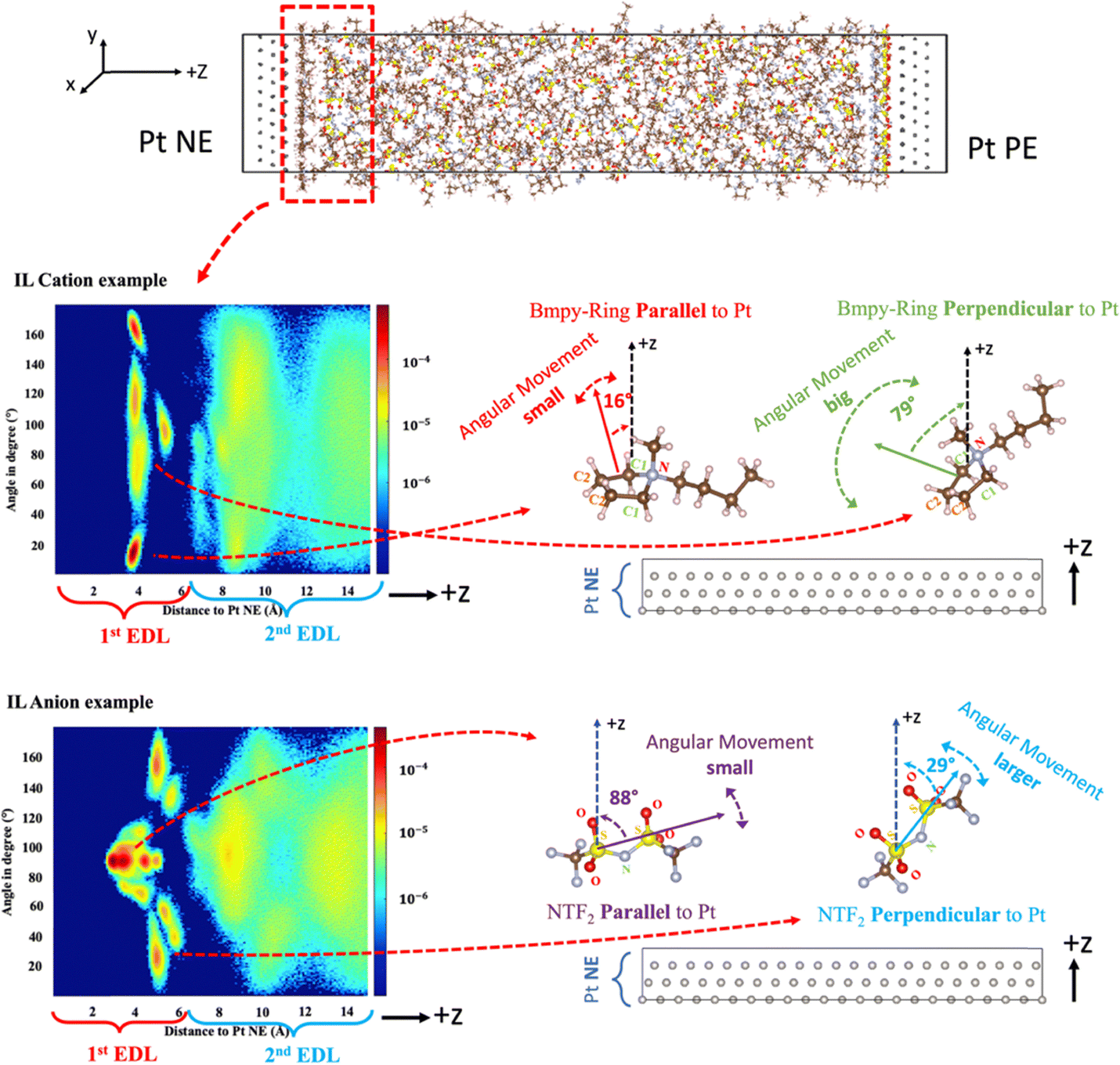 | ||
| Fig. 5 Schematic of IL orientation distribution: using [Bmpy] and [NTf2]Bmpy near the NE region (Pt Q = −8 e) as an example. For [Bmpy], an angle close to 0° or 180° indicates that the cation ring tends to stay parallel to the electrode, and the angular movement of this molecule is usually small. If the angle of a cation is close to 90°, the molecule tends to remain perpendicular to the electrode, usually with big angular movement. For [NTf2]Bmpy, an angle close to 90° suggests a parallel configuration with small angular movement, while an angle near 0° or 180° indicates a perpendicular configuration with larger angular movement. | ||
For [Bmpy] inside the 1st EDL, there exist two types of characteristic molecular orientations. The first type corresponds to the two red spots in the top (close to 180°) and bottom (close to 0°), and the IL cation rings are in parallel with the electrode surface at such orientations. Meanwhile, at this configuration, the distributions appear as spots with confined y-space, indicating a small angular movement. The second type relates to the two orange/yellow ribbons close to 90°. At this configuration, IL cation rings stay at a nearly perpendicular direction to the electrode surface, with a large angular movement indicated by the elongated angle distributions (ribbons instead of spots). Similarly for [NTf2]Bmpy, two types of characteristic orientations exist: the first type relates to an orientation parallel to the electrode surface, with small angular movement, indicated by the red spots close to 90°. The second type corresponds to the orientation almost perpendicular to the electrode surface with larger angular movement, as indicated by the two orange/yellow ribbons located close to 0° and 180°. In addition, for both IL cations and anions, the parallel orientation dominates as compared to the perpendicular orientation, as indicated by their color difference, especially in the case of using a logarithmic scale for the color legend.
The complete orientation distribution comparison between two ILs is shown below for cations and anions under various electrode charge conditions at both electrodes (Fig. 6–9). For cations in the NE region (Fig. 6), the orientation distributions in general change little with the electrode charges. There are also some changes with respect to the small yellow color stripes of angles ranging from ∼70° to ∼110°, at 5–6 Å away from the Pt surface, which correspond to the tiny shoulder peaks in the N distributions as shown in the top of Fig. 4a. In the meantime, for cations in the PE region (Fig. 8) with the charge value going up, there are more yellow color stripes that show up in the region at 4–7 Å to the electrode surface, and the color stripes in the 2nd EDL turned yellower, especially at 8–10 Å to the electrode surface. This is in line with expectations, as more cations are repelled away from the PE, and thus granted more freedom of movement, consistent with the decreasing sharp peak heights ([Bmpy] peak: at ∼3.8 Å, [Bmim] peak: at ∼2.9 Å) in the N distributions results (Fig. 4b, top). Overall, in the closest vicinity to the electrode (within 4 Å) under each charge condition, most cations stay parallel to the electrode surface (∼0/180°) in both IL species, but the cation orientations in [Bmpy] show a more scattered distribution than [Bmim]. In a H2 sensor, the hydrogen molecules need to first be transported through the 1st EDL of PE to reach the electrode, before the redox reaction can happen. A cation ring staying parallel to the electrode surface tends to have a high possibility of blocking the H2 transport pathway to the Pt surface than a perpendicular configuration. Thus, the more scattered orientation distribution in [Bmpy][NTf2] makes it easier for H2 to reach both electrodes, and thus a higher redox reaction possibility than that in [Bmim][NTf2]. In addition, the closer distance of red spots in [Bmpy] compared with [Bmim] is consistent with the number (N) distribution in Fig. 4.
 | ||
| Fig. 6 IL cation orientation distribution near the Pt NE region: [Bmpy] (top row) vs. [Bmim] (bottom row), under different Pt electrode charge conditions. | ||
 | ||
| Fig. 7 IL anion orientation distribution near the Pt NE region: [NTf2]Bmpy (top row) vs. [NTf2]Bmim (bottom row), under different Pt electrode charge conditions. | ||
 | ||
| Fig. 8 IL cation orientation distribution near the Pt PE region: [Bmpy] (top row) vs. [Bmim] (bottom row), under different Pt electrode charge conditions. | ||
 | ||
| Fig. 9 IL anion orientation distribution near the Pt PE region: [NTf2]Bmpy (top row) vs. [NTf2]Bmim (bottom row), under different Pt electrode charge conditions. | ||
For anions in the NE region (Fig. 7), closest to the electrodes are two red spots centered at 90°. They are located at around a 3 Å distance from the NE surface, with a gap of ∼0.4 Å between the two spots. The centers of the two spots look maroon, suggesting a high probability of occurrence. They correspond to the first two sub-peaks at 2.8 Å and 3.3 Å in the N distributions as shown in the bottom of Fig. 4a, and the associated anions prefer staying parallel to the electrode surface with small angular movement. When farther away from the NE, there exist multiple orange/yellow ribbons in the region of 4–6 Å away from the electrode, which are symmetrical with respect to 90° degrees. All these anions in the region, pertaining to various orientations, contribute together to the formation of the third sub-peak (4.8 Å) in N distributions (Fig. 4a, bottom). In addition, when the charge on NE changes from −5 e to −8 e, such orange stripes at 4–6 Å expand both in size and intensity for [NTf2]Bmpy and [NTf2]Bmim, indicating that more anions are repelled into this region from the inner interfacial region (<4 Å). For anions in the PE region (Fig. 9), more anions get attracted to the electrode with more charges on PE, and the isolated yellow stripes at 4–6 Å diminish. This is anticipated, as when anions are drawn to the electrode, there are more restrictions on their movement, and thus more tendency for them to stay parallel (∼90°) to the electrode surface. Besides that, under each charge condition at both electrodes, the orientation distributions of [NTf2]Bmim and [NTf2]Bmpy are mostly similar. Inside the 1st EDL, almost all [NTf2] anions stay parallel to the electrode surface on the PE side, while on the NE side, there is a much higher possibility for [NTf2] to stay non-parallel to the Pt surface, although the parallel paradigm still dominates. This is understandable, as the positive charges in the PE strongly attract the [NTf2] anions, while the negative charges in the NE side may repel [NTf2] out, allowing more freedom of the anion orientation. When it comes to the 2nd EDL, like the IL cations, the molecule orientation becomes more randomly distributed in all test cases, while there is indeed a slightly higher chance of [NTf2] staying parallel to the Pt surface than other orientations.
Considering the results from both the N and orientation distributions, the difference in using various electrode charge values will only lead to changes in magnitude, but the EDL heterostructures and their main structural features remain unchanged. No matter which electrode charge value is used, the electrolyte|electrode interphase could always be classified into three regions: The 1st EDL stays closest to the electrode and displays sharp peaks in N distributions with a predominate parallel molecule orientation. The 2nd EDL stays beyond 6–7 Å way from the electrode, and the bulk region stays even further away. Thus, for the subsequent analysis of the EDL structure, we will only base them on the case where the electrode charge is ±8 e.
 | ||
| Fig. 10 IL molecular displacements along the z-axis: using [Bmpy] near the PE region (Pt Q = +8 e) as an example. | ||
Fig. 10 also shows that the heterostructure could be divided into three regions depending on the distance to the Pt electrodes, similar to the findings from the number/orientation distribution. When closest to Pt electrodes, the error bar of the molecules is quite small, with typical std values of ∼0.1–0.3 Å, meaning that the molecular movement along the z-axis is highly restricted. This corresponds to the 1st EDL with a boundary located around 6 Å away from the electrode. Farther away from the electrode, there are many IL molecules exhibiting larger error bar lengths, with the typical std values becoming 0.5–2.0 Å. This shows that molecules were granted greater freedom of movement along the z-axis at a greater distance from the electrode but were still somewhat limited. This matches the 2nd EDL in the N distributions. As compared to the 1st EDL|2nd EDL boundary, the boundary between the 2nd EDL and bulk region becomes vague, but it is still reasonable to say that it is around 15.0 Å combining the findings from the number/orientation distribution. Beyond the 2nd EDL, the error bar of an IL molecule appears noticeably larger, with std values becoming 4–10 Å, or even larger. This suggests that the molecular displacement become completely unconstrained along the z-axis in the bulk region.
 | ||
| Fig. 11 Schematic of the whole simulation cell based on the results of the number distribution, molecule orientation, and molecule displacement. | ||
In the 1st EDL at both electrodes (NE-1L and PE-1L), the IL molecular movement along the z-axis is highly restricted with little displacement. Most molecules tend to stay parallel to the electrode surface, and their angular movement is constrained. The 1st EDL extends about 6 Å away from the electrode surface in our test, although this boundary value might vary for different types of IL. Beyond the 1st EDL extending further into the bulk (6–16 Å), is where the 2nd EDL (NE-2L, PE-2L) is located, where the IL molecular movement along the z-axis is still limited, but with more freedom as compared to that in the 1st EDL. Meanwhile, the IL molecules show a mostly random orientation distribution, with slight preference of staying parallel to the electrode surface, and their angular movement is unconstrained as compared to that in the 1st EDL. With such characteristics, it is hard to set a strict boundary for the 2nd EDL with the bulk phase, like the 1st EDL|2nd EDL boundary. The 2nd EDL|Bulk boundary is located around 16 Å away from electrode surface, but could be longer depending on the IL species, temperature, etc. Beyond the 2nd EDL is the bulk region located in the middle of the simulation cell, where the effect of the electrodes diminishes and can be considered as neglected. In the bulk region, the IL molecular movement becomes large and unconstrained. Meanwhile, the molecule orientations become randomly distributed completely with large, unconstrained angular movement.
This kind of 3-region and 2-double-layer structure phenomenon aligns with previously reported studies.29,34,82–85 According to previous studies,83,84 the IL|Electrode interfacial region could be split into three discrete regions: (1) the boundary/Stern (surface-adsorbed) layer, corresponding to our 1st EDL; (2) the transition (near-surface) zone, corresponding to our 2nd EDL; and (3) the bulk phase, which could be confirmed by experiments like atomic force microscopy (AFM) measurement.34,85
 | ||
| Fig. 12 Self-diffusivity values of IL (a) cations and (b) anions along the x/y axis and z-axis in the five regions (Pt Q = ±8 e). | ||
In each figure, the blue and red dashed lines refer to the IL molecule D values in the pure [Bmpy][NTf2] and [Bmim][NTf2] case (without adding Pt electrodes and hydrogen particles), extracted from Fig. 2a. The calculated D values in the 2nd EDLs & 1st EDLs look symmetrical at the NE side and PE side, with respect to the bulk phase. For both IL cations and anions in either [Bmpy][NTf2] or [Bmim][NTf2], the D values in the 2nd EDL are 1–2 orders of magnitude smaller than that in the bulk phase, and the D values in the 1st EDL decrease further by 1–2 orders of magnitude as compared to the 2nd EDL. In addition, the D values along the z-axis are always smaller than their counterparts along the x/y axis. For example, in the 1st EDL, the difference is at least 1 order of magnitude. Such trends are as expected, as the Pt electrode is placed on the xy-plane. The anisotropy becomes reduced in the 2nd EDL and negligible in the bulk. D values in the bulk region are consistent with those in bulk ILs (dashed lines) from Fig. 2c.
 . The results in Fig. 13b show that the ratio of P([Bmpy][NTf2]) to P([Bmim][NTf2]) is clearly larger than 1.0 in the 1st EDL of both electrodes under all electrode charge conditions, while the ratios in the 2nd EDL and bulk are close to 1.0. This suggests that the H2 movement activity in both the bulk and 2nd EDL regions should be similar for the two IL species, and it should be the H2 probability density in the 1st EDL that contributes to the different H2 sensibility of the two IL species. In addition, among all regions, the PE-1L region captures the most interest, as this is where an H2 molecule gets oxidized. It shows that H2 molecules have a higher possibility of staying in the PE-1L in [Bmpy][NTf2] than in [Bmim][NTf2] under all electrode charge conditions. Among all the electrode charge conditions, the H2 probability density difference between [Bmpy][NTf2] and [Bmim][NTf2] in PE-1L is the highest at Q = +5 e, while the lowest is at Q = +8 e. The H2 probability density is affected by the molecular structure of cations and anions and their energetic interaction with H2. Thus, it might be difficult to pinpoint exactly the atomic origin as to why the density difference between these two ionic liquids behaves this way. However, as discussed previously in the N distribution (Fig. 4b), increased electrode charge tends to repel cations and attract anions, indicating a diminishing difference in PE-1L between [Bmpy][NTf2] and [Bmim][NTf2] as they have the same anions. This explains why there is the lowest probability density difference at the highest charge condition (Q = +8 e).
 | ||
| Fig. 13 (a) H2 probability density (Å−1) in different regions under different Pt electrode charge conditions: Q = ±2 e (black), Q = ±5 e (red), and Q = ±8 e (blue); (b) the ratio of H2 probability density in [Bmpy][NTf2] to probability density in [Bmim][NTf2] for different regions under different Pt electrode charge conditions: Q = ±2 e (black), Q = ±5 e (red), and Q = ±8 e (blue). | ||
Another way to look at H2 probability is to examine the integrated N density distribution as shown in Fig. 14, using Pt Q = +8 e as an example. There is no H2 in the region within 2 Å away from the Pt PE electrode. This is understandable as both Pt and H atoms have their van der Waals sizes. Within PE-1L (circled), H2 mostly stay in a narrow region of 2–3 Å, right on the Pt surface, and it appears that the probability of finding H2 is higher in [Bmpy][NTf2] than in [Bmim][NTf2].
 | ||
| Fig. 14 Comparison of the integrated H2 probability within 10 Å of the PE region (Pt Q = ±8 e): [Bmpy][NTf2] vs. [Bmim][NTf2]. | ||
Conclusions
In order to explain why [Bmpy][NTf2] is a better electrolyte material than [Bmim][NTf2] as observed in hydrogen sensing experiments, MD simulation was employed in this study to investigate the different structures in [Bmpy][NTf2] and [Bmim][NTf2] based hydrogen sensors. First, both IL cations and anions, along with the H2 molecules, demonstrate a higher self-diffusivity in [Bmpy][NTf2] than in [Bmim][NTf2], excluding the possibility that it is the molecule diffusion in bulk IL that makes a difference. Second, the electrolyte|electrode interphase is investigated and compared between the two IL species. The heterostructure can be classified into three distinct regions depending on the distance to the electrode surface: the 1st EDL, the 2nd EDL, and the bulk phase, and their features can be well described using descriptors including IL number distributions, IL molecule orientation distributions, and their displacements along the z-axis. Furthermore, the whole simulation cell is divided into five distinct regions from NE to PE, with one 1st EDL and one 2nd EDL for each electrode, and the self-diffusivities of IL cations and anions are then calculated for each region, respectively. To the best of our knowledge, this is the first time of reporting the diffusion-related difference in the 1st and 2nd EDL, and the bulk phase, besides their structural difference like IL ion arrangements.29,34,82–85 The electrolyte|electrode interfaces of the two IL species are mostly similar except for the cations in the 1st EDL, in which [Bmpy] ions have a more scattered orientation distribution than [Bmim] ions. Considering that a parallel cation configuration has a higher chance of obstructing the H2 transport pathway to the Pt surface, and H2 molecules need to first diffuse through the 1st EDL to reach the PE before the oxidation, more H2 transport pathways to the Pt surface are made available in [Bmpy][NTf2], resulting in a higher H2 redox reaction possibility.When it comes to the H2 molecules, first, H2 indeed demonstrates a slightly higher solubility in [Bmpy][NTf2]. Additionally, as part of a comparative study, even with the same amount of H2 molecules injected into the electrochemical simulation cell, our probability density results still show that there is a higher likelihood of finding H2 molecules inside the 1st EDL of the PE in [Bmpy][NTf2] than in [Bmim][NTf2]. These results align with our observations on the IL molecule orientations and thereby altogether elucidate why [Bmpy][NTf2] is a more sensitive electrolyte in hydrogen sensors than [Bmim][NTf2].
Data availability
Input data for this article are available at https://github.com/yininghe/Simulation_Compare_2ILs.Conflicts of interest
There are no conflicts to declare.Acknowledgements
This material is based upon work supported by the U.S. Department of Energy's Office of Energy Efficiency and Renewable Energy (EERE) under the Hydrogen Fuel Cells Technologies Office (HFTO) and Funding Opportunity in Support of the Hydrogen Shot and a University Research Consortium on Grid Resilience, Award Number DE-EE0010744. In addition, we would like to express our appreciation to the High-Performance Computing Center and the Institute for Cyber-Enabled Research at Michigan State University for supplying the computational resources.References
- S.-Y. Cho, H. Ahn, K. Park, J. Choi, H. Kang and H.-T. Jung, Ultrasmall Grained Pd Nanopattern H2 Sensor, ACS Sens., 2018, 3(9), 1876–1883, DOI:10.1021/acssensors.8b00834.
- H. Wang, X. Liu, Y. Fang, X. Zeng and C. C. Cao, Printed, Flexible, Ionic Liquid-Based Hydrogen Sensor via Aerosol Jet Printing of Nanomaterials, IEEE Sens. Lett., 2023, 7(6), 1–4, DOI:10.1109/LSENS.2023.3272779.
- M. Z. Jacobson, W. G. Colella and D. M. Golden, Cleaning the Air and Improving Health with Hydrogen Fuel-Cell Vehicles, Science, 2005, 308(5730), 1901–1905, DOI:10.1126/science.1109157.
- T. Hübert, L. Boon-Brett, G. Black and U. Banach, Hydrogen sensors – A review, Sens. Actuators, B, 2011, 157(2), 329–352, DOI:10.1016/j.snb.2011.04.070.
- B. Sharma, A. Sharma and J.-S. Kim, Recent advances on H2 sensor technologies based on MOX and FET devices: A review, Sens. Actuators, B, 2018, 262, 758–770, DOI:10.1016/j.snb.2018.01.212.
- D. S. Silvester, Recent advances in the use of ionic liquids for electrochemical sensing, Analyst, 2011, 136(23), 4871–4882, 10.1039/C1AN15699C.
- J. R. Stetter and J. Li, Amperometric Gas Sensors A Review, Chem. Rev., 2008, 108(2), 352–366, DOI:10.1021/cr0681039.
- G. Korotcenkov, S. D. Han and J. R. Stetter, Review of Electrochemical Hydrogen Sensors, Chem. Rev., 2009, 109(3), 1402–1433, DOI:10.1021/cr800339k.
- J. R. Stetter and K. F. Blurton, Portable high-temperature catalytic reactor: Application to air pollution monitoring instrumentation, Rev. Sci. Instrum., 1976, 47(6), 691–694, DOI:10.1063/1.1134709.
- B. E. Conway and B. V. Tilak, Interfacial processes involving electrocatalytic evolution and oxidation of H2, and the role of chemisorbed H, Electrochim. Acta, 2002, 47(22), 3571–3594, DOI:10.1016/S0013-4686(02)00329-8.
- Y. Tang and X. Zeng, Electrochemical Oxidation of Hydrogen in Bis(trifluoromethylsulfonyl)imide Ionic Liquids under Anaerobic and Aerobic Conditions, J. Phys. Chem. C, 2016, 120(41), 23542–23551, DOI:10.1021/acs.jpcc.6b07067.
- V. Nikolova, I. Nikolov, P. Andreev, V. Najdenov and T. Vitanov, Tungsten carbide-based electrochemical sensors for hydrogen determination in gas mixtures, J. Appl. Electrochem., 2000, 30(6), 705–710, DOI:10.1023/A:1003813210270.
- Y. Tan and T. C. Tan, Sensing Behavior of an Amperometric Hydrogen Sensor: Theoretical Modeling and Experimental Verification, J. Electrochem. Soc., 1995, 142(6), 1923, DOI:10.1149/1.2044215.
- T. Asset, et al., A Review on Recent Developments and Prospects for the Oxygen Reduction Reaction on Hollow Pt-alloy Nanoparticles, ChemPhysChem, 2018, 19(13), 1552–1567, DOI:10.1002/cphc.201800153.
- L. Zhang, K. Doyle-Davis and X. Sun, Pt-Based electrocatalysts with high atom utilization efficiency: from nanostructures to single atoms, Energy Environ. Sci., 2019, 12(2), 492–517, 10.1039/C8EE02939C.
- G. A. Rîmbu, et al., Electrochemical Sensor for Hydrogen Leakage Detection at Room Temperature, Sensors, 2025, 25(1), 1, DOI:10.3390/s25010264.
- E. Jayanthi, N. Murugesan, A. S. Suneesh, C. Ramesh and S. Anthonysamy, Sensing Behavior of Room Temperature Amperometric H2 Sensor with Pd Electrodeposited from Ionic Liquid Electrolyte as Sensing Electrode, J. Electrochem. Soc., 2017, 164(8), H5210, DOI:10.1149/2.0331708jes.
- Y.-C. Weng and K.-C. Hung, Amperometric hydrogen sensor based on PtxPdy/Nafion electrode prepared by Takenata–Torikai method, Sens. Actuators, B, 2009, 141(1), 161–167, DOI:10.1016/j.snb.2009.06.035.
- Y. Chao, S. Yao, W. J. Buttner and J. R. Stetter, Amperometric sensor for selective and stable hydrogen measurement, Sens. Actuators, B, 2005, 106(2), 784–790, DOI:10.1016/j.snb.2004.09.042.
- T. Gunnlaugsson, M. Glynn, G. M. Tocci (née Hussey), P. E. Kruger and F. M. Pfeffer, Anion recognition and sensing in organic and aqueous media using luminescent and colorimetric sensors, Coord. Chem. Rev., 2006, 250(23), 3094–3117, DOI:10.1016/j.ccr.2006.08.017.
- Y. Shao, J. Wang, H. Wu, J. Liu, I. A. Aksay and Y. Lin, Graphene Based Electrochemical Sensors and Biosensors: A Review, Electroanalysis, 2010, 22(10), 1027–1036, DOI:10.1002/elan.200900571.
- D. R. MacFarlane, et al., Ionic liquids and their solid-state analogues as materials for energy generation and storage, Nat. Rev. Mater., 2016, 1(2), 2, DOI:10.1038/natrevmats.2015.5.
- G. Hussain, M. Ge, C. Zhao and D. S. Silvester, Fast responding hydrogen gas sensors using platinum nanoparticle modified microchannels and ionic liquids, Anal. Chim. Acta, 2019, 1072, 35–45, DOI:10.1016/j.aca.2019.04.042.
- G. Hussain, M. V. Sofianos, J. Lee, C. Gibson, C. E. Buckley and D. S. Silvester, Macroporous platinum electrodes for hydrogen oxidation in ionic liquids, Electrochem. Commun., 2018, 86, 43–47, DOI:10.1016/j.elecom.2017.11.011.
- Y. Tang, J. He, X. Gao, T. Yang and X. Zeng, Continuous amperometric hydrogen gas sensing in ionic liquids, Analyst, 2018, 143(17), 4136–4146, 10.1039/C8AN00577J.
- Z. Huang, et al., Miniaturized Electrochemical Gas Sensor with a Functional Nanocomposite and Thin Ionic Liquid Interface for Highly Sensitive and Rapid Detection of Hydrogen, Anal. Chem., 2024, 96(45), 17960–17968, DOI:10.1021/acs.analchem.4c02561.
- H. Tokuda, K. Hayamizu, K. Ishii, Md. A. B. H. Susan and M. Watanabe, Physicochemical Properties and Structures of Room Temperature Ionic Liquids. 1. Variation of Anionic Species, J. Phys. Chem. B, 2004, 108(42), 16593–16600, DOI:10.1021/jp047480r.
- H. Tokuda, K. Ishii, M. A. B. H. Susan, S. Tsuzuki, K. Hayamizu and M. Watanabe, Physicochemical properties and structures of room-temperature ionic liquids. 3. Variation of cationic structures, J. Phys. Chem. B, 2006, 110(6), 2833–2839, DOI:10.1021/jp053396f.
- R. Hayes, G. G. Warr and R. Atkin, Structure and Nanostructure in Ionic Liquids, Chem. Rev., 2015, 115(13), 6357–6426, DOI:10.1021/cr500411q.
- Q. Zhang, Y. Han, Y. Wang, S. Ye and T. Yan, Comparing the differential capacitance of two ionic liquid electrolytes: Effects of specific adsorption, Electrochem. Commun., 2014, 38, 44–46, DOI:10.1016/j.elecom.2013.10.027.
- J. P. Embs, T. Burankova, E. Reichert and R. Hempelmann, Cation Dynamics in the Pyridinium Based Ionic Liquid 1-N-Butylpyridinium Bis((trifluoromethyl)sulfonyl) As Seen by Quasielastic Neutron Scattering, J. Phys. Chem. B, 2012, 116(44), 13265–13271, DOI:10.1021/jp3070344.
- N. C. Osti, A. Gallegos, B. Dyatkin, J. Wu, Y. Gogotsi and E. Mamontov, Mixed Ionic Liquid Improves Electrolyte Dynamics in Supercapacitors, J. Phys. Chem. C, 2018, 122(19), 10476–10481, DOI:10.1021/acs.jpcc.8b02521.
- M. L. Hoarfrost, M. Tyagi, R. A. Segalman and J. A. Reimer, Proton Hopping and Long-Range Transport in the Protic Ionic Liquid [Im][TFSI], Probed by Pulsed-Field Gradient NMR and Quasi-Elastic Neutron Scattering, J. Phys. Chem. B, 2012, 116(28), 8201–8209, DOI:10.1021/jp3044237.
- F. Endres, N. Borisenko, S. Z. E. Abedin, R. Hayes and R. Atkin, The interface ionic liquid(s)/electrode(s): In situSTM and AFM measurements, Faraday Discuss., 2011, 154, 221–233, 10.1039/C1FD00050K.
- R. Burt, G. Birkett and X. S. Zhao, A review of molecular modelling of electric double layer capacitors, Phys. Chem. Chem. Phys., 2014, 16(14), 6519–6538, 10.1039/C3CP55186E.
- J. Vatamanu, O. Borodin and G. D. Smith, Molecular Simulations of the Electric Double Layer Structure, Differential Capacitance, and Charging Kinetics for N-Methyl-N-propylpyrrolidinium Bis(fluorosulfonyl)imide at Graphite Electrodes, J. Phys. Chem. B, 2011, 115(12), 3073–3084, DOI:10.1021/jp2001207.
- M. V. Fedorov and A. A. Kornyshev, Towards understanding the structure and capacitance of electrical double layer in ionic liquids, Electrochim. Acta, 2008, 53(23), 6835–6840, DOI:10.1016/j.electacta.2008.02.065.
- Z. Hu, J. Vatamanu, O. Borodin and D. Bedrov, A comparative study of alkylimidazolium room temperature ionic liquids with FSI and TFSI anions near charged electrodes, Electrochim. Acta, 2014, 145, 40–52, DOI:10.1016/j.electacta.2014.08.072.
- K. Kirchner, T. Kirchner, V. Ivaništšev and M. V. Fedorov, Electrical double layer in ionic liquids: Structural transitions from multilayer to monolayer structure at the interface, Electrochim. Acta, 2013, 110, 762–771, DOI:10.1016/j.electacta.2013.05.049.
- Y. Shim, H. J. Kim and Y. Jung, Graphene-based supercapacitors in the parallel-plate electrode configuration: Ionic liquids versus organic electrolytes, Faraday Discuss., 2011, 154, 249–263, 10.1039/C1FD00086A.
- S. Jo, S.-W. Park, C. Noh and Y. Jung, Computer simulation study of differential capacitance and charging mechanism in graphene supercapacitors: Effects of cyano-group in ionic liquids, Electrochim. Acta, 2018, 284, 577–586, DOI:10.1016/j.electacta.2018.07.126.
- C. Noh and Y. Jung, Understanding the charging dynamics of an ionic liquid electric double layer capacitor via molecular dynamics simulations, Phys. Chem. Chem. Phys., 2019, 21(13), 6790–6800, 10.1039/C8CP07200K.
- D. S. Silvester, L. Aldous, C. Hardacre and R. G. Compton, An Electrochemical Study of the Oxidation of Hydrogen at Platinum Electrodes in Several Room Temperature Ionic Liquids, J. Phys. Chem. B, 2007, 111(18), 5000–5007, DOI:10.1021/jp067236v.
- J. N. Canongia Lopes, J. Deschamps and A. A. H. Pádua, Modeling Ionic Liquids Using a Systematic All-Atom Force Field, J. Phys. Chem. B, 2004, 108(6), 2038–2047, DOI:10.1021/jp0362133.
- J. N. Canongia Lopes and A. A. H. Pádua, Molecular Force Field for Ionic Liquids III:
![[thin space (1/6-em)]](https://www.rsc.org/images/entities/char_2009.gif) Imidazolium, Pyridinium, and Phosphonium Cations; Chloride, Bromide, and Dicyanamide Anions, J. Phys. Chem. B, 2006, 110(39), 19586–19592, DOI:10.1021/jp063901o.
Imidazolium, Pyridinium, and Phosphonium Cations; Chloride, Bromide, and Dicyanamide Anions, J. Phys. Chem. B, 2006, 110(39), 19586–19592, DOI:10.1021/jp063901o. - J. N. Canongia Lopes, A. A. H. Pádua and K. Shimizu, Molecular Force Field for Ionic Liquids IV: Trialkylimidazolium and Alkoxycarbonyl-Imidazolium Cations; Alkylsulfonate and Alkylsulfate Anions, J. Phys. Chem. B, 2008, 112(16), 5039–5046, DOI:10.1021/jp800281e.
- J. N. Canongia Lopes and A. A. H. Pádua, CL&P: A generic and systematic force field for ionic liquids modeling, Theor. Chem. Acc., 2012, 131(3), 1129, DOI:10.1007/s00214-012-1129-7.
- W. L. Jorgensen, D. S. Maxwell and J. Tirado-Rives, Development and Testing of the OPLS All-Atom Force Field on Conformational Energetics and Properties of Organic Liquids, J. Am. Chem. Soc., 1996, 118(45), 11225–11236, DOI:10.1021/ja9621760.
- W. D. Cornell, et al., A Second Generation Force Field for the Simulation of Proteins, Nucleic Acids, and Organic Molecules, J. Am. Chem. Soc., 1995, 117, 5179–5197 CrossRef CAS; W. D. Cornell, et al. , J. Am. Chem. Soc., 1996, 118(9), 2309, DOI:10.1021/ja955032e.
- B. Doherty, X. Zhong, S. Gathiaka, B. Li and O. Acevedo, Revisiting OPLS Force Field Parameters for Ionic Liquid Simulations, J. Chem. Theory Comput., 2017, 13(12), 6131–6145, DOI:10.1021/acs.jctc.7b00520.
- K. Cui, A. Yethiraj and J. R. Schmidt, Influence of Charge Scaling on the Solvation Properties of Ionic Liquid Solutions, J. Phys. Chem. B, 2019, 123(43), 9222–9229, DOI:10.1021/acs.jpcb.9b08033.
- H. Heinz, R. A. Vaia, B. L. Farmer and R. R. Naik, Accurate Simulation of Surfaces and Interfaces of Face-Centered Cubic Metals Using 12–6 and 9–6 Lennard-Jones Potentials, J. Phys. Chem. C, 2008, 112(44), 17281–17290, DOI:10.1021/jp801931d.
- S. Wang, K. Hou and H. Heinz, Accurate and Compatible Force Fields for Molecular Oxygen, Nitrogen, and Hydrogen to Simulate Gases, Electrolytes, and Heterogeneous Interfaces, J. Chem. Theory Comput., 2021, 17(8), 5198–5213, DOI:10.1021/acs.jctc.0c01132.
- S. Plimpton, Fast Parallel Algorithms for Short-Range Molecular Dynamics, J. Comput. Phys., 1995, 117(1), 1–19, DOI:10.1006/jcph.1995.1039.
- A. P. Thompson, et al., LAMMPS – a flexible simulation tool for particle-based materials modeling at the atomic, meso, and continuum scales, Comput. Phys. Commun., 2022, 271, 108171, DOI:10.1016/j.cpc.2021.108171.
- M. J. Abraham, et al., GROMACS: high performance molecular simulations through multi-level parallelism from laptops to supercomputers, Softwarex, 2015, 1–2, 19–25, DOI:10.1016/j.softx.2015.06.001.
- S. Nosé, A unified formulation of the constant temperature molecular dynamics methods, J. Chem. Phys., 1984, 81(1), 511–519, DOI:10.1063/1.447334.
- W. G. Hoover, Canonical dynamics: Equilibrium phase-space distributions, Phys. Rev. A:At., Mol., Opt. Phys., 1985, 31(3), 1695–1697, DOI:10.1103/PhysRevA.31.1695.
- G. Bussi, D. Donadio and M. Parrinello, Canonical sampling through velocity rescaling, J. Chem. Phys., 2007, 126, 1, DOI:10.1063/1.2408420.
- M. P. Allen and D. J. Tildesley, Computer Simulation of Liquids, Oxford University Press, 2017 Search PubMed.
- J.-P. Ryckaert, G. Ciccotti and H. J. C. Berendsen, Numerical integration of the cartesian equations of motion of a system with constraints: molecular dynamics of n-alkanes, J. Comput. Phys., 1977, 23(3), 327–341, DOI:10.1016/0021-9991(77)90098-5.
- B. Hess, H. Bekker, H. J. C. Berendsen and J. Fraaije, LINCS: A linear constraint solver for molecular simulations, J. Comput. Chem., 1997, 18(12), 1463–1472 CrossRef CAS.
- L. Verlet, Computer ‘Experiments’ on Classical Fluids. I. Thermodynamical Properties of Lennard-Jones Molecules, Phys. Rev., 1967, 159(1), 98–103, DOI:10.1103/PhysRev.159.98.
- T. G. A. Youngs, A ten—An application for the creation, editing, and visualization of coordinates for glasses, liquids, crystals, and molecules, J. Comput. Chem., 2010, 31(3), 639–648, DOI:10.1002/jcc.21359.
- C. H. Bennett, Efficient Estimation Of Free-Energy Differences From Monte-Carlo Data, J. Comput. Phys., 1976, 22(2), 245–268, DOI:10.1016/0021-9991(76)90078-4.
- E. Helfand, Transport Coefficients from Dissipation in a Canonical Ensemble, Phys. Rev., 1960, 119(1), 1–9, DOI:10.1103/PhysRev.119.1.
- S. S. Sarangi, W. Zhao, F. Müller-Plathe and S. Balasubramanian, Correlation between Dynamic Heterogeneity and Local Structure in a Room-Temperature Ionic Liquid: A Molecular Dynamics Study of [bmim][PF6], ChemPhysChem, 2010, 11(9), 2001–2010, DOI:10.1002/cphc.201000111.
- M. H. Kowsari, S. Alavi, M. Ashrafizaadeh and B. Najafi, Molecular dynamics simulation of imidazolium-based ionic liquids. I. Dynamics and diffusion coefficient, J. Chem. Phys., 2008, 129(22), 224508, DOI:10.1063/1.3035978.
- S. M. Urahata and M. C. C. Ribeiro, Single particle dynamics in ionic liquids of 1-alkyl-3-methylimidazolium cations, J. Chem. Phys., 2004, 122(2), 024511, DOI:10.1063/1.1826035.
- H. Vogel, Das Temperaturabhangigkeitsgesetz der Viskositat von Flussigkeiten, Phys. Z., 1921, 22, 645–646 CAS.
- G. Tammann and W. Hesse, Die Abhängigkeit der Viscosität von der Temperatur bie unterkühlten Flüssigkeiten, Z. Anorg. Allg. Chem., 1926, 156(1), 245–257, DOI:10.1002/zaac.19261560121.
- G. S. Fulcher, Analysis of Recent Measurements of the Viscosity of Glasses, J. Am. Ceram. Soc., 1925, 8(6), 339–355, DOI:10.1111/j.1151-2916.1925.tb16731.x.
- M. F. Friedrich, S. Kokolakis, M. Lucas and P. Claus, Measuring Diffusion and Solubility of Slightly Soluble Gases in [CnMIM][NTf2] Ionic Liquids, J. Chem. Eng. Data, 2016, 61(4), 1616–1624, DOI:10.1021/acs.jced.5b00990.
- T. Klein, et al., Diffusivities in Binary Mixtures of [AMIM][NTf2] Ionic Liquids with the Dissolved Gases H2, He, N2, CO, CO2, or Kr Close to Infinite Dilution, J. Chem. Eng. Data, 2020, 65(8), 4116–4129, DOI:10.1021/acs.jced.0c00430.
- D. S. Frenkel, Understanding Molecular Simulation: From Algorithms to Applications, Academic Press, 2002 Search PubMed.
- P. J. Dyson, G. Laurenczy, C. A. Ohlin, J. Vallance and T. Welton, Determination of hydrogen concentration in ionic liquids and the effect (or lack of) on rates of hydrogenation, Chem. Commun., 2003, 2418–2419, 10.1039/b308309h.
- A. A. Kornyshev, Double-Layer in Ionic Liquids: Paradigm Change?, J. Phys. Chem. B, 2007, 111(20), 5545–5557, DOI:10.1021/jp067857o.
- M. V. Fedorov and A. A. Kornyshev, Ionic Liquids at Electrified Interfaces, Chem. Rev., 2014, 114(5), 2978–3036, DOI:10.1021/cr400374x.
- S. Begić, F. Chen, E. Jónsson and M. Forsyth, Overscreening and crowding in electrochemical ionic liquid systems, Phys. Rev. Mater., 2019, 3(9), 095801, DOI:10.1103/PhysRevMaterials.3.095801.
- S.-W. Park, A. D. DeYoung, N. R. Dhumal, Y. Shim, H. J. Kim and Y. Jung, Computer Simulation Study of Graphene Oxide Supercapacitors: Charge Screening Mechanism, J. Phys. Chem. Lett., 2016, 7, 1180–1186, DOI:10.1021/acs.jpclett.6b00202.
- Y. Wang, Y. Sun, Y. Dong and G. Tian, Characterization of the Interface Structure of 1-Ethyl-2,3-alkylimidazolium Bis(trifluoromethylsulfonyl)imide on a Au(111) Surface with Molecular Dynamics Simulations, J. Phys. Chem. B, 2021, 125(14), 3677–3689, DOI:10.1021/acs.jpcb.0c09994.
- M. Z. Bazant, B. D. Storey and A. A. Kornyshev, Double Layer in Ionic Liquids: Overscreening versus Crowding, Phys. Rev. Lett., 2011, 106(4), 046102, DOI:10.1103/PhysRevLett.106.046102.
- D. S. Silvester, R. Jamil, S. Doblinger, Y. Zhang, R. Atkin and H. Li, Electrical Double Layer Structure in Ionic Liquids and Its Importance for Supercapacitor, Battery, Sensing, and Lubrication Applications, J. Phys. Chem. C, 2021, 125(25), 13707–13720, DOI:10.1021/acs.jpcc.1c03253.
- H. Li, T. Niemann, R. Ludwig and R. Atkin, Effect of Hydrogen Bonding between Ions of Like Charge on the Boundary Layer Friction of Hydroxy-Functionalized Ionic Liquids, J. Phys. Chem. Lett., 2020, 11(10), 3905–3910, DOI:10.1021/acs.jpclett.0c00689.
- J. M. Black, et al., Bias-Dependent Molecular-Level Structure of Electrical Double Layer in Ionic Liquid on Graphite, Nano Lett., 2013, 13(12), 5954–5960, DOI:10.1021/nl4031083.
| This journal is © the Owner Societies 2025 |