A MALDI-chip integrated system with a monitoring window
Monica
Brivio
a,
Niels R.
Tas
b,
Martijn H.
Goedbloed
b,
Han J. G. E.
Gardeniers
b,
Willem
Verboom
*a,
Albert
van den Berg
b and
David N.
Reinhoudt
*a
aLaboratory of Supramolecular Chemistry and Technology, MESA+ Institute for Nanotechnology, University of Twente, P.O. Box 217, 7500 AE, Enschede, The Netherlands. E-mail: w.verboom@utwente.nl; Fax: +31 (0)53 4894645; Tel: +31 (0)53 4892980
bBIOS Lab-on-a-chip Group, MESA+ Institute for Nanotechnology, University of Twente, P.O. Box 217, 7500 AE, Enschede, The Netherlands. Fax: +31 (0)53 4893595; Tel: +31 (0)53 4894356
First published on 16th February 2005
Abstract
The integration of a monitoring port along the microfluidic path of a MALDI-chip integrated device is described. Optimization of the microreactor design allows longer reaction and measuring times. The Schiff base reaction between 4-tert-butylaniline (1) and 4-tert-butylbenzaldehyde (2) in ethanol was carried out on-chip in the MALDI ionization chamber and the formed imine 3 was detected in real time, demonstrating the feasibility of the “monitoring window” approach. This preliminary result opens the way to on-chip kinetic studies by MALDI-MS, by opening multiple monitoring windows along the microchannel.
Introduction
Recently, we reported the first example of a microfluidic system integrated with a matrix-assisted laser desorption ionization (MALDI)1,2 time-of-flight (TOF) mass spectrometer (MS).3 Reactions were initiated by using the vacuum of the instrument to actuate solutions within the microreactor. An important novelty of such an integrated microfluidic device is the possibility of analyzing the reaction product “on the spot” by MALDI-MS immediately after the reaction has taken place. After the chip is placed in the MALDI-TOF vacuum chamber, and as soon as the reaction product reaches the outlet, the laser beam ionizes the molecules, which are detected by the TOF analyzer.In the previous design, due to the channel geometry, very high flow rates were generated using the vacuum-driven actuation, which resulted in very short residence times. Furthermore, the reaction mixture could only be analyzed at one sampling spot (the outlet) where the reaction mixtures were collected. As a consequence no time-dependent experiments could be done. Proper design of the fluidic circuit and the integration of multiple outlet-ports, would allow a quasi-continuous monitoring of the reaction products in time, extending the use of the MALDI-chip to kinetic studies.
In this communication the fabrication of a microreactor that allows longer reaction and measuring times is reported. A novel concept is described consisting of the integration of a “monitoring window” in the chip design, for monitoring reactions by using the MALDI-chip set-up. As a model reaction the Schiff base reaction4 between 4-tert-butylaniline (1) and 4-tert-butylbenzaldehyde (2) in ethanol to give the corresponding imine 3 (Scheme 1) was carried out on the MALDI-chip and the reaction product was detected through the “monitoring window”.
 | ||
| Scheme 1 Schiff base formation reaction. | ||
Experimental
Microreactors
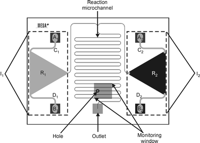
Microreactors (Fig. 1) were fabricated in the cleanroom facility of the MESA+ Institute for Nanotechnology at the University of Twente. Inlet and outlet holes as well as the “monitoring window” were fabricated in the top silicon wafer by KOH wet-etching5 in combination with a boron etch stop.6 The reaction microchannel was fabricated in the bottom borofloat wafer by HF etching,7 while the triangular reservoirs as well as the bigger inlet channels (going from the inlet holes to the reservoirs) were fabricated by powder-blast micromachining.8,9 Square-shaped holes in the monitoring window were fabricated by focused ion beam (FIB). Various combinations of dimensions and number of holes were investigated. The preliminary experiment reported in this paper was carried out using a monitoring window with only one sampling hole of 500 × 500 nm.Reagents
Reagents were obtained from Aldrich Chemicals, The Netherlands, and were used as supplied commercially without further purification. No matrix was added for the MALDI detection of the imine 3, because of its strong absorption at the laser wavelength (λ = 337 nm). Reservoir A was filled with a solution of 1 × 10⁻⁴ M 4-tert-butylaniline (1) in ethanol, reservoir B was filled with a solution of 1 × 10⁻⁴ M 4-tert-butylbenzaldehyde (2) in ethanol.Filling procedure
The reservoirs filling procedure was monitored by mounting the chip, placed on a suitable holder, on an Olympus CK40M inverted microscope.MALDI-TOF
The reaction product formed in the microreactor channel was identified in real time through a nm size hole fabricated in the “monitoring window” by MALDI-TOF MS using a Voyager-DE-RP MALDI-TOF mass spectrometer (Applied Biosystems/PerSeptive Biosystems, Inc., Framingham, MA, USA) equipped with delayed extraction,10,11 and a 337 nm UV nitrogen laser, producing 3 ns pulses. The mass spectra were obtained in the reflectron mode.Focused ion beam (FIB)
Holes in the boron doped silicon membranes (250 × 250 nm and 500 × 500 nm) were made using a FEI 200 Focused Ion Beam System. The resulting holes were imaged in situ using a Scanning Electron Microscope (SEM).Results and discussion
Fluid dynamics
A high degree of temporal control over the (micro)fluidics is a prerequisite to carrying out time-dependent studies of (bio)chemical reactions. In the recently developed3 MALDI-based lab-on-a-chip the fluid is transported through the channels due to a pressure difference between the inlet, where a small air bubble is present (atmospheric pressure) and the outlet (vacuum). The relation between the generated flow rate and the applied vacuum pressure is defined by eqn. (1).12,13| Δp = R × ϕν | (1) |
 | (2) |
 | (3) |
It is clear that no time-dependent experiments are possible using this microfluidic device, since the residence times are in the order of two hundred milliseconds. Even when opening multiple sampling ports along the channel, the time necessary to move the ionizing laser from one window to the next would be much too long compared to the on-chip residence times. Channels that have a higher hydraulic resistance are a possible solution to the short on-chip residence times. A new microfluidic system was therefore designed to allow a longer residence time.
Microreactor optimization
A microreactor was designed (Fig. 1) having 30 µm wide, 10 µm deep and 125 mm long channels, fabricated in a glass substrate by wet chemical etching using HF. The hydraulic resistance and residence time in this new channel design were calculated using eqns. (2) and (3) to give values of R = 6.3 × 10¹⁶ N s m−5 and tr = 24 s, respectively. | ||
| Fig. 1 Outline of the chip used to prove the “monitoring window” principle. Each inlet loading system (Ix) consists of two inlet holes (Ax and Bx) connected to a reservoir (Rx) through channels Cx and Dx (with x = 1 and 2). | ||
Due to downscaling, the surface free energy15,16 (“surface tension”) becomes considerable. As a consequence, the contribution of the capillary pressure to the MALDI-chip pumping mechanism might be significant. For a flat rectangular channel the capillary pressure Pc (N m−2) is given by eqn. (4).17,18
 | (4) |
Although the estimated residence times in the new microchannel are about 2 orders of magnitude higher than those in the previous MALDI-chip design, they are still too short to study reaction kinetics by MALDI-MS. Nevertheless, a considerably longer total measurement time (∼75 min) can be obtained by the introduction of relatively large reservoirs for the reagent solutions (vide infra). This chip was therefore used to demonstrate the feasibility of extracting ions from a solution flowing in a microchannel through a hole in a silicon membrane
The key element of the new microreactor (Fig. 1) is the “monitoring window”. This consists of a freestanding ∼2 µm thick silicon membrane doped with boron, positioned above the channel (Fig. 2a). Ions can be extracted from the flowing reaction mixture through holes fabricated in the silicon membrane. Holes (250 × 250 and 500 × 500 nm), which could be visualized by scanning electron microscopy (SEM), were made by means of a focused ion beam (FIB). A micrograph of the 250 × 250 nm holes is given in Fig. 2b. The hole dimensions are important, since a pressure drop along the channel may arise from too large holes in the membrane, affecting the microfluidic actuation mechanism. Both hole sizes tested in the experiments here reported were big enough to allow analysis of the reaction mixture without significantly affecting the main flow through the reaction microchannel. A new chip design with multiple “monitoring windows” will require resizing the sampling holes, based on the channel geometry, the number of openings along the channels and the vacuum system used to transport the liquid. The position and dimensions of the “monitoring window” are also important factors. The dimensions of the window in the top silicon wafer must be large enough to let the laser beam, which hits the chip surface under an angle of about 30°, reach the small hole fabricated in the doped silicon layer on the bottom side of the same wafer. In these experiments 2.2 mm by 2.5 mm “monitoring windows” were fabricated, which gave good results.
 | ||
| Fig. 2 (a) Cross-section of the silicon–glass hybrid chip with a KOH etched “monitoring window” and a sampling hole above the HF microchannel. (b) SEM image of 250 × 250 nm sampling holes made by FIB in the doped silicon layer. | ||
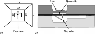
In the first version of the MALDI-chip,3 reagent solutions were loaded in inlet cups fabricated in the top wafer by powder-blast micromachining. The inlets were then sealed with adhesive tape. A drawback of this inlet system is that the liquid can easily be contaminated by coming into contact with the adhesive used to seal the inlet holes. A new reagent loading scheme was developed (Fig. 1) consisting of two inlet systems (I1 and I2). Each system comprises two via-holes etched in the top silicon wafer (A1, B1 and A2, B2, respectively), a triangular reservoir (R1 and R2), and two 200 µm wide by 100 µm deep powder-blasted channels (C1, D1, and C2, D2) that connect each inlet hole with the corresponding reservoir. Flap valves19 (Fig. 3a) were fabricated in the doped silicon layer at the bottom of the inlet holes (Fig. 3b). These valves open during the filling position upon applying pressure onto the inlet (vide infra) and thereby allow the reagent solution to fill the reservoir. When the pressure is released, the valves close, separating the loaded solutions from the glue, and thereby eliminating the risk of contamination. The triangular reservoirs (5.4 mm high, 6.2 mm wide, 100 µm deep) were powder-blasted in the bottom glass wafer.
 | ||
| Fig. 3 (a) Top view of the flap valve at the bottom side of each inlet hole (the dimensions are given in mm) and (b) cross-section of the inlet hole with flap valve, glass slide and glue. | ||
Testing the “monitoring window”
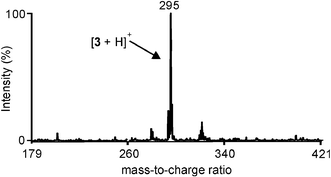
The reservoirs were filled by suction of reagent solutions using a syringe. During the filling procedure the chip was positioned in a suitable holder. About 3 µL of reagent solutions were placed in hole A1 or A2, while the syringe was placed on hole B1 or B2. Each reservoir was filled keeping the corner where the small channel starts dry. This prevented filling of the reaction channel due to capillary forces before the chip was introduced into the ionization chamber (see inlet system I2 in Fig. 1). During the filling procedure holes A1 and A2 were emptied completely, thereby trapping air bubbles in the powder-blasted channels (see inlet system I2 in Fig. 1). In order to prevent the liquid from filling the reaction channel before entering the MALDI chamber, all other openings (outlet, monitoring window, and second inlet) were sealed with adhesive tape during the filling of each inlet. After both reagents were placed in the reservoirs, the four inlet holes were closed using a UV-curable glue. A glass slide (700 × 700 µm) was placed in the inlet holes to prevent the glue from entering the inlet channels and polluting the reactants. After introducing the chip into the ionization chamber of the MALDI instrument, the air bubbles trapped behind the liquids expanded, pushing the reagent solutions into the reaction channel.To prove the principle of the “monitoring window” the Schiff base formation reaction between 4-tert-butylaniline (1) and 4-tert-butylbenzaldehyde (2) in ethanol (Scheme 1) was carried out using the MALDI-chip system equipped with the chip in Fig. 1. The chip on the MALDI sample plate was introduced into the vacuum chamber by load lock. The first MALDI-TOF mass spectrum was acquired as soon as the plate reached the right spot in the chamber. The analysis was started after about 1 min. Ions were extracted from the channel through the hole, by hitting the “monitoring window” with the laser. The reaction product, imine 3, was clearly visible in the mass spectrum at m/z = 295 (Fig. 4). Even after about 1 h, imine 3 could still be detected, indicating that reagent solutions were still available for the reaction, as predicted by theoretical calculations.
 | ||
| Fig. 4 MALDI-TOF mass spectrum of the imine 3 (m/z = 295) formed on-chip within the ionization chamber of the MALDI instrument and detected by extracting ions from the reaction mixture through the monitoring window. | ||
After the last mass spectrum was recorded (∼1 h), the chip was examined using an optical microscope. The air bubbles in the reservoirs had expanded into the channel, while liquid was still present in the portion of the channel close to the outlet.
Conclusions and outlook
A “monitoring window” for real time reaction monitoring was integrated into the design of a microfluidic chip. As proof of the principle, the product (imine 3) of the on-chip Schiff base reaction of 4-tert-butylaniline (1) and 4-tert-butylbenzaldehyde (2) in ethanol was detected by MALDI-TOF mass spectrometry through the “monitoring window”. Although preliminary, this important result clearly demonstrates the feasibility of extracting ions from a flowing solution for analysis of the reaction mixture composition, opening the way to kinetic studies of (bio)chemical reactions by MALDI-TOF MS. The scope of the presented method might be extended to non absorbing analytes by adding a matrix to one of the reagent solutions,3 provided that the selected matrix does not interfere with the chemical reaction under investigation.Acknowledgements
The authors would like to thank Vishwas Gadgil, who operated the FIB, and the Micro Chemical Systems (MiCS) program of the MESA+ Institute for Nanotechnology and the University of Twente for financial support.Notes and references
- M. Karas and F. Hillenkamp, Anal. Chem., 1988, 60, 3523.
- A. Overberg, M. Karas, U. Bahr, R. Kaufmann and F. Hillenkamp, Rapid Commun. Mass Spectrom., 1990, 4, 293 CAS.
- M. Brivio, R. H. Fokkens, W. Verboom, D. N. Reinhoudt, N. R. Tas, M. H. Goedbloed and A. Van den Berg, Anal. Chem., 2002, 74, 3972 CrossRef CAS.
- T. W. G. Solomons, Fundamentals of Organic Chemistry, John Wiley & Sons, New York, 5th edn., 2000, ch. 8 Search PubMed.
- K. E. Petersen, IEEE Trans. Electron Devices, 1978, 25, 1241 CrossRef.
- H. Seidel, L. Csepregi, A. Heuberger and H. Baumgärtel, J. Electrochem. Soc., 1990, 137, 3626 CAS.
- T. Corman, P. Enoksson and G. J. Stemme, J. Micromech. Microeng., 1998, 8, 84 CrossRef CAS.
- H. Wensink, J. W. Berenschot, H. V. Jansen and M. C. Elwenspoek, Proc. 13th Int. Workshop on MicroMechanical Systems (MEMS 2000), Miyazaki, Japan, IEEE, 2000, 769 Search PubMed.
- P. J. Slikkerveer, P. C. P. Bouten and F. C. M. De Haas, Sens. Actuators, A, 2000, 85, 296 CrossRef.
- M. L. Vestal, P. Juhasz and S. A. Martin, Rapid Commun. Mass Spectrom., 1995, 9, 1044 CAS.
- P. Juhasz, M. L. Vestal and S. A. Martin, J. Am. Soc. Mass Spectrom., 1997, 8, 209 CrossRef CAS.
- F. W. White, Fluid Mechanics, McGraw-Hill, New York, 3rd edn., 1994 Search PubMed.
- T. S. J. Lammerink, N. R. Tas, J. W. Berenschot, M. C. Elwenspoek and J. H. J. Fluitman, 8th Int. Workshop on MicroMechanical Systems (MEMS 1995), Amsterdam, The Netherlands, IEEE, 1995, 13 Search PubMed.
- R. E. Oosterbroek, Ph.D Thesis, University of Twente, Enschede, The Netherlands, 1999.
- A. W. Adamson and A. P. Gast, Physical Chemistry of Surfaces, John Wiley & Sons, New York, 6th edn., 1997 Search PubMed.
- R. F. Probstein, Physicochemical Hydrodynamics, an Introduction, John Wiley & Sons, New York, 2nd edn., 1994 Search PubMed.
- P. W. Atkins, Physical Chemistry, Oxford University Press, Oxford, 5th edn., 1994, ch. 28 Search PubMed.
- N. R. Tas, J. W. Berenschot, T. S. J. Lammerink, M. C. Elwenspoek and A. Van den Berg, Anal. Chem., 2002, 74, 2224 CrossRef CAS.
- R. Zengerle, J. Ulrich, S. Kluge, M. Richter and A. Richter, Sens. Actuators, A, 1005, 50, 81 Search PubMed.
| This journal is © The Royal Society of Chemistry 2005 |
