 Open Access Article
An all organic redox flow battery with high cell voltage
Yongjie Huoab,
Xueqi Xingab,
Cuijuan Zhang *ab,
Xiang Wangab and
Yongdan Li*abc
aState Key Laboratory of Chemical Engineering, Tianjin Key Laboratory of Applied Catalysis Science and Technology, School of Chemical Engineering and Technology, Tianjin University, Tianjin 300072, China. E-mail: cjzhang@tju.edu.cn; ydli@tju.edu.cn
bCollaborative Innovation Center of Chemical Science and Engineering (Tianjin), Tianjin, 300072, China
cDepartment of Chemical and Metallurgical Engineering, School of Chemical Engineering, Aalto University, Kemistintie 1, P. O. Box 16100, FI-00076, Espoo, Finland. E-mail: yongdan.li@aalto.fi
First published on 29th April 2019
Abstract
An all organic redox flow battery with 4,4′-dimethylbenzophenone (44DMBP) anolyte and 2,5-di-tert-butyl-1,4-dimethoxybenzene (DBB) catholyte shows a high open circuit voltage of 2.97 V, and average coulombic efficiency of 72% over 95 cycles at a current density of 1 mA cm−2.
1 Introduction
The large-scale integration of renewable energy sources such as solar and wind brings about great challenges to the stability and safety of the electrical-grid which has always been disrupted by peak loads. To circumvent such awkwardness, it is greatly desirable to develop energy storage technologies to balance electricity generation and demand.1 In such context, redox flow batteries (RFBs) stand out due to their characteristics of high safety and low cost.2–4 Since the dissolved redox active materials are stored separately in external tanks rather than in the electrodes, the decoupled configuration makes RFBs highly flexible in capacity and energy component design. The conventional aqueous RFBs such as all vanadium RFBs have achieved significant successes in recent years and have reached the stage of commercialization.5 However, the low specific energy densities, limited by the narrow electrochemical stability window of water, has led to high cost and thus is disadvantageous in competition with other energy storage technologies for deeper market penetration. Correspondingly, developing non-aqueous RFBs is a promising strategy to enhance the energy densities owing to the wider electrochemical windows of organic electrolytes.2,4,6Matsuda et al. first reported non-aqueous RFB system with Ru(bpy)3 as the active species in the tetraethylammonium tetrafluoroborate/acetonitrile electrolyte with an open circuit voltage (OCV) of 2.6 V,7 followed by work on other metal–ligand complexes such as V(acac)3,8 cobalt and vanadium trimetaphosphate,9 [Cu(MeCN)4][Tf2N],10 ferrocene and cobaltocene11 as the redox active materials. However, such RFBs suffered from low energy density primarily due to their low solubility in the electrolyte. An alternative approach was pioneered by Li et al. in 2011.12 They developed the non-aqueous all-organic RFBs with organic redox active species, 2,2,6,6-tetramethyl-1-piperidinyloxy (TEMPO) and N-methylphthalimide as cathode and anode active species, respectively, which achieved OCV of 1.6 V. Since then, all-organic RFBs have received increasing attention because the organic compounds generally have low molecular weight, high solubility, and wide source compared with common metal complexes.2,4
The commercial development of RFBs highly depends on their cost. An overall cost of $100 (kW h)−1 is targeted to match with the traditional physical energy storage technologies.13 To achieve this goal for non-aqueous RFBs, besides reducing the area specific resistance of the battery, selecting low molar mass active materials with multiple electron-transfers, and using a low salt ratio, increasing the cell voltage (≥3.0 V) is the most effective approach and thus is an important milestone.14 However, the cell voltage achieved for all-organic RFBs up to date is much lower than 3 V. For example, the Wei group reported that RFB constructed with 9-fluorenone and 2,1,3-benzothiadiazole (BzNSN) anolytes and 2,5-di-tert-butyl-1-methoxy-4-[2′-methoxyethoxy]benzene (DBMMB) catholyte provided OCVs of 2.37 and 2.36 V, respectively.15,16 A similar cell assembled with OCH3-substituted BzNSN anolyte and DBMMB catholyte showed OCV of 2.496 V.17 Therefore, it is greatly desirable to develop new active materials to obtain high cell voltage.
The cell voltage can be modified by engineering the active compounds.4 The general principle is that functionalization of electron-withdrawing/donating groups can increase/decrease the electron affinity of molecules and thus higher/lower redox potential. Both experimental and computational results have proved the effect of functional groups.17,18 Our previous work showed that benzophenone (BP) can be a good anolyte candidate due to its low redox potential, high electrochemical stability, and high solubility in non-aqueous electrolyte.19 An all-organic cell with BP anolyte and TEMPO catholyte provided a voltage of 2.41 V.19 2,5-Di-tert-butyl-1,4-dimethoxybenzene (DBB) was an excellent redox shuttle additive for overcharge protection in lithium-ion batteries and shows a high half-wave potential of 4.32 V vs. Li/Li+.20 Furthermore, a number of 1,4-dimethoxybenzene (DB) derivatives have been studied as catholyte for RFBs.21 Therefore, DBB can be used as catholyte. Herein, BP was modified with various substitutes in order to achieve high cell voltage. The resultant all-organic cell delivered high cell OCV of 2.97 V and average coulombic efficiency of 72% over 95 cycles.
2 Experimental
2.1 Materials
The compounds benzophenone (BP, 98%, Tianjin Guangfu Fine Chemical Research Institute), acetonitrile (MeCN, 98%, Tianjin Guangfu Fine Chemical Research Institute), 2,5-di-tert-butyl-1,4-dimethoxybenzene (DBB, 99%, Shanghai Bide Pharmatech Ltd.), 4,4′-dimethylbenzophenone (44DMBP, 98%, Tianjin Heowns Biochemical Technology Co., Ltd), 4,4′-dimethoxylbenzophenone (44DMOBP, 98%, Tianjin Heowns Biochemical Technology Co., Ltd), and 4-nitrobenzophenone (4NBP, 99%, Tianjin Heowns Biochemical Technology Co., Ltd) were used as received except MeCN, which was dried to remove moisture thoroughly with CaH2. The tetraethylammonium hexafluorophosphate (TEAPF6) was synthesized according to our previously reported procedure.19 The AMI-7001 anion-exchange membrane (Membranes-International Ltd., USA) was dried in vacuum at 70 °C for 24 h before use.2.2 Cyclic voltammetry (CV) test
The CV test was performed with VersaSTAT 3 potentiostat/galvanostat (Princeton Applied Research, USA) on a three-electrode, with glassy carbon (6 mm in diameter, Aidahengsheng), graphite plate (6 cm2 in geometry surface area), and an Ag/Ag+ (0.5 M AgNO3 in MeCN solution) as working, counter, and reference electrodes, respectively. A mixed reactant electrolyte of TEAPF6/MeCN containing 1![[thin space (1/6-em)]](https://www.rsc.org/images/entities/char_2009.gif) :
:![[thin space (1/6-em)]](https://www.rsc.org/images/entities/char_2009.gif) 1 molar ratio of anolyte
1 molar ratio of anolyte![[thin space (1/6-em)]](https://www.rsc.org/images/entities/char_2009.gif) :
:![[thin space (1/6-em)]](https://www.rsc.org/images/entities/char_2009.gif) DBB (0.01 M
DBB (0.01 M![[thin space (1/6-em)]](https://www.rsc.org/images/entities/char_2009.gif) :
:![[thin space (1/6-em)]](https://www.rsc.org/images/entities/char_2009.gif) 0.01 M) was selected. Prior to all CV experiment, the oxygen dissolved in the electrolyte solutions was removed completely by continuously circulating nitrogen gas.
0.01 M) was selected. Prior to all CV experiment, the oxygen dissolved in the electrolyte solutions was removed completely by continuously circulating nitrogen gas.
The diffusion coefficient was calculated using the Randles–Sevcik equations for reversible and irreversible electrode reactions:
For reversible reactions:
| ip = 2.69 × 10⁵n3/2AcD1/2ν1/2 | (1) |
For irreversible reactions:
| ip = 2.99 × 10⁵n3/2α1/2AcD1/2ν1/2 | (2) |
2.3 Flow battery test
The flow battery performance was tested on a home-made battery with VersaSTAT 3 potentiostat/galvanostat (Princeton Applied Research, USA) in an argon-filled glove box (Mikrouna, china) with both H2O and O2 levels below 1 ppm. The battery was assembled with an AMI-7001 anion-exchange membrane, two non-porous graphite plates current collector, and two graphite felt (20 mm × 20 mm × 5 mm) electrodes. The graphite felt (Morgan Advanced Materials Co., Ltd., bulk density 0.08 g cm−3, thickness 5 mm) was used as received without further treatment. It is of high purity with carbon content >99.9%. The compression ratio of the graphite felt electrode is ∼10% to ensure optimal electrical conductivity. The anion-exchange membrane was soaked for more than 24 h in 0.5 M TEAPF6/MeCN solution before test. Electrolyte composition was 5 mM 44DMBP/5 mM DBB in 0.5 M TEAPF6/CH3CN solution. Galvanostatic cycling of the cell was performed at a charge/discharge current density of 1.0 mA cm−2/1.0 mA cm−2, respectively. The volume of the electrolyte was 12 mL.3 Results and discussion
3.1 Electrode reaction and electrode potential
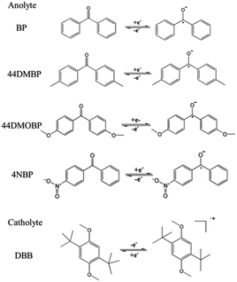
The redox reactions of anolytes and catholyte are shown in Scheme 1. The redox potential of active materials was first examined by CV with a three-electrode cell in a mixed reactant electrolyte of TEAPF6/MeCN containing a 1![[thin space (1/6-em)]](https://www.rsc.org/images/entities/char_2009.gif) :
:![[thin space (1/6-em)]](https://www.rsc.org/images/entities/char_2009.gif) 1 molar ratio of anolyte
1 molar ratio of anolyte![[thin space (1/6-em)]](https://www.rsc.org/images/entities/char_2009.gif) :
:![[thin space (1/6-em)]](https://www.rsc.org/images/entities/char_2009.gif) DBB (0.01 M
DBB (0.01 M![[thin space (1/6-em)]](https://www.rsc.org/images/entities/char_2009.gif) :
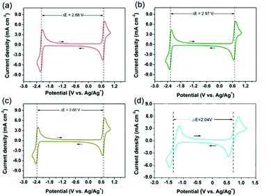
:![[thin space (1/6-em)]](https://www.rsc.org/images/entities/char_2009.gif) 0.01 M). TEAPF6 in MeCN was selected as the electrolyte considering its high ion conductivity and low viscosity.4,15,22 All the CV curves at the sweep rate of 0.5 V s−1 are shown in Fig. 1. The oxidation of DBB to DBB+ radical cation takes place at 0.75 V while the reverse reaction at 0.66 V vs. Ag/Ag+. Therefore, the half-wave potential of DBB/DBB+ redox couple is 0.71 V vs. Ag/Ag+. The redox potentials of DBB/DBB+ couple remain constant when different anolytes were employed. Different anolytes show distinctively different potentials. The half-wave potentials of BP/BP−, 44DMBP/44DMBP−, 44DMOBP/44DMOBP−, and 4NBP/4NBP− are −2.17, −2.26, −2.37, and −1.33 V vs. Ag/Ag+, respectively. Accordingly, the cell voltages with DBB catholyte and BP, 44DMBP, 44DMOBP, and 4NBP anolytes are 2.88, 2.97, 3.08, and 2.04 V, respectively. The 44DMBP/DBB and 44DMOBP/DBB cells achieve the targeted voltage of 3.0 V. Such values are significantly higher than that reported (Fig. 2). To the best of our knowledge, 3.08 V is the highest value achieved for all organic RFBs.
0.01 M). TEAPF6 in MeCN was selected as the electrolyte considering its high ion conductivity and low viscosity.4,15,22 All the CV curves at the sweep rate of 0.5 V s−1 are shown in Fig. 1. The oxidation of DBB to DBB+ radical cation takes place at 0.75 V while the reverse reaction at 0.66 V vs. Ag/Ag+. Therefore, the half-wave potential of DBB/DBB+ redox couple is 0.71 V vs. Ag/Ag+. The redox potentials of DBB/DBB+ couple remain constant when different anolytes were employed. Different anolytes show distinctively different potentials. The half-wave potentials of BP/BP−, 44DMBP/44DMBP−, 44DMOBP/44DMOBP−, and 4NBP/4NBP− are −2.17, −2.26, −2.37, and −1.33 V vs. Ag/Ag+, respectively. Accordingly, the cell voltages with DBB catholyte and BP, 44DMBP, 44DMOBP, and 4NBP anolytes are 2.88, 2.97, 3.08, and 2.04 V, respectively. The 44DMBP/DBB and 44DMOBP/DBB cells achieve the targeted voltage of 3.0 V. Such values are significantly higher than that reported (Fig. 2). To the best of our knowledge, 3.08 V is the highest value achieved for all organic RFBs.
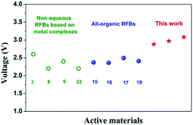 | ||
| Fig. 2 Comparison of open-circuit voltage of cells in this work and that in literature. The numbers inset are the reference numbers.7–9,15–17,19,23 | ||
The substituent groups with different electronegativity have different effects on the redox potential of the active materials.4 When electron-donating functional groups are added, the excess electrons on the functional group are pushed onto the ring, leading to larger electron cloud density on the ring. Those electrons are easily lost and thus more energetically favorable oxidation and lower oxidation potentials. On the other hand, when electron-withdrawing groups are added, the active molecule will form an electron-poor ring, from which the electrons cannot be easily lost. Accordingly, the cell voltage can be tailored by substituting with electron-donating or withdrawing groups. Owing to their electron-donating characteristics, methyl and methoxy groups in 44DMBP and 44DMOBP can increase the electron density of the BP groups and thus lower the redox potential, leading to high cell voltage. In contrast, the nitro group in 4NBP is electron-withdrawing, which lowers the electron density of BP and thus more positive potential, resulting in low cell voltage.
Although the 44DMOBP/DBB couple shows the highest cell voltage in this work, its solubility in MeCN is lower by 8-fold than 44DMBP (0.09 vs. 0.8 mol L−1) at room temperature. Because the energy density of RFBs is determined by the concentration of active materials, high solubility is undoubtedly desirable.4 Considering that the OCV of 44DMBP/DBB is only slightly smaller than that of 44DMOBP/DBB (2.97 vs. 3.08 V), and is very close to 3.0 V, the following characterization was focused on the 44DMBP/DBB cell.
3.2 Electrochemical kinetics
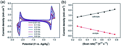
The diffusion properties of active materials are extremely important to achieve high cell performance. Accordingly, CVs at various scan rates were employed to derive the diffusion coefficients. The CV curves of 44DMBP/DBB active species at the scan rates from 0.07 to 0.6 V s−1 are shown in Fig. 3a. The separations between oxidation and reduction peaks of 44DMBP and DBB redox couples are 70.2–80.7 mV and ∼76 mV, respectively, at all the scan rates studied in this work. In addition, the ratio of oxidation to reduction peak current densities of 44DMBP and DBB are 0.92–1.03 and ∼0.98, respectively, very close to unity. All these results indicate that both electrode redox reactions can be considered quasi-reversible. The peak current density as a function of (scan rate)1/2 is shown in Fig. 3b. The linear relationship suggests that both electrode reactions are controlled by diffusion process. The diffusion coefficients of 44DMBP and DBB are calculated to be 1.23–1.97 × 10⁻⁵ and 0.77–1.23 × 10⁻⁵ cm2 s−1, respectively, based on the Randles–Sevcik equations, which are among the high diffusivity values.19,213.3 Electrochemical performance
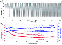
44DMBP/DBB was assembled into RFB to evaluate their battery cycling performance with two graphite felt electrodes and AMI-7001 anion-exchange membrane. Two non-porous graphite plates were used as the current collectors. The active materials were a mixture of 5 mM 44DMBP/5 mM DBB in 0.5 M TEAPF6/MeCN. Here, a mixed-reactant electrolyte was employed to alleviate the crossover of the active species.15 The discharge/charge voltages were cut off at 0/4 V. The voltage profile of discharge/charge processes at the current density of 1 mA cm−2 is shown in Fig. 4a. The charge voltage increases at the first several cycles until to 4 V. The cycling duration decreases with cycle number, indicating performance degradation. As shown in Fig. 4b, both the discharge and charge capacity decreased quickly with cycling at the initial ten cycles, and very slowly afterwards. The average discharge/charge capacity is 52.1/72.9 mA h L−1 over 95 cycles. The corresponding coulombic and voltage efficiencies are rather stable over the cycling duration, averaged at 72% and 47%, respectively.Although the cell with 44DMBP/DBB couples shows high OCV (2.97 V), the overpotentials during charging and discharging are high, leading to poor performance compared with that in literature.15,16 As is well-known, the RFBs performance is very sensitive to many factors such as the active materials, electrodes, membranes.2,4 In this work, thick anion exchange membrane AMI-7001 (0.45 mm in thickness) was used. High thickness and low ion conductivity of this membrane resulted in high ohmic loss, leading to poor performance. Wei et al. found that the supporting electrolytes had a significant impact on the chemical stability of the charged radial species and thus affected the cycling stability.15 Similar problems were probably also present in our system. The battery chemistry during charging/discharging involves the formation of 44DMBP˙−, which is susceptible to electron-deficient group and can launch a nucleophilic attack. 44DMBP˙− possibly attacks part of the low electron cloud density of acetonitrile and TEABF6 molecules used as solvent and supporting electrolyte in this work. In addition, electrolyte crossover and leakage from the pumping system can also lead to capacity decay.24 Development of new membranes and supporting electrolytes of high performance and also optimization of battery configurations are expected to enhance the RFB performance, which is under progress in our laboratory.
4 Conclusions
The substituent groups in the active materials have a significant influence on the voltage of RFB. The substitution of BP with electron-donating groups can increase the cell open-circuit voltage to around 3 V with 44DMBP/DBB and 44DMOBP/DBB couples. Both 44DMBP and DBB show high diffusion ability in TEAPF6/MeCN electrolyte. RFB with 44DMBP/DBB as active materials shows average discharge capacity of 52.1 mA h L−1 and coulombic efficiency of 72% over 95 cycles at the current density of 1 mA cm−2.Conflicts of interest
There are no conflicts to declare.Acknowledgements
The financial support of NSF of China under contract number 21636007 is gratefully acknowledged. This work has also been supported by the Program of Introducing Talents to the University Disciplines under file number B06006, and the Program for Changjiang Scholars and Innovative Research Teams in Universities under file number IRT 0641.Notes and references
- B. Dunn, H. Kamath and J.-M. Tarascon, Science, 2011, 334, 928 CrossRef CAS PubMed
.
- X. Wei, W. Pan, W. Duan, A. Hollas, Z. Yang, B. Li, Z. Nie, J. Liu, D. Reed, W. Wang and V. Sprenkle, ACS Energy Lett., 2017, 2, 2187 CrossRef CAS
.
- J. Winsberg, T. Hagemann, T. Janoschka, M. D. Hager and U. S. Schubert, Angew. Chem., Int. Ed., 2017, 56, 686 CrossRef CAS PubMed
.
- Y. Ding, C. Zhang, L. Zhang, Y. Zhou and G. Yu, Chem. Soc. Rev., 2018, 47, 69 RSC
.
- P. Leung, X. Li, C. Ponce de León, L. Berlouis, C. T. J. Low and F. C. Walsh, RSC Adv., 2012, 2, 10125 RSC
.
- R. M. Darling, K. G. Gallagher, J. A. Kowalski, S. Ha and F. R. Brushett, Energy Environ. Sci., 2014, 7, 3459 RSC
.
- Y. Matsuda, K. Tanaka, M. Okada, Y. Takasu, M. Morita and T. Matsumura-Inoue, J. Appl. Electrochem., 1988, 18, 909 CrossRef CAS
.
- Q. Liu, A. E. S. Sleightholme, A. A. Shinkle, Y. Li and L. T. Thompson, Electrochem. Commun., 2009, 11, 2312 CrossRef CAS
.
- J. M. Stauber, S. Zhang, N. Gvozdik, Y. Jiang, L. Avena, K. J. Stevenson and C. C. Cummins, J. Am. Chem. Soc., 2018, 140, 538 CrossRef CAS PubMed
.
- S. Schaltin, Y. Li, N. R. Brooks, J. Sniekers, I. F. J. Vankelecom, K. Binnemans and J. Fransaer, Chem. Commun., 2016, 52, 414 RSC
.
- H. Byunghyun, P. Min-Sik and K. Ketack, ChemSusChem, 2015, 8, 310 CrossRef PubMed
.
- Z. Li, S. Li, S. Liu, K. Huang, D. Fang, F. Wang and S. Peng, Electrochem. Solid-State Lett., 2011, 14, A171 CrossRef CAS
.
- U. S. DOE, Grid energy storage, 2013 Search PubMed
.
- P. Leung, A. A. Shah, L. Sanz, C. Flox, J. R. Morante, Q. Xu, M. R. Mohamed, C. Ponce de León and F. C. Walsh, J. Power Sources, 2017, 360, 243 CrossRef CAS
.
- X. Wei, W. Xu, J. Huang, L. Zhang, E. Walter, C. Lawrence, M. Vijayakumar, W. A. Henderson, T. Liu, L. Cosimbescu, B. Li, W. Sprenkle and W. Wang, Angew. Chem., Int. Ed., 2015, 54, 8684 CrossRef CAS PubMed
.
- W. Duan, J. Huang, J. A. Kowalski, I. A. Shkrob, M. Vijayakumar, E. Walter, B. Pan, Z. Yang, J. D. Milshtein, B. Li, C. Liao, Z. Zhang, W. Wang, J. Liu, J. S. Moore, F. R. Brushett, L. Zhang and X. Wei, ACS Energy Lett., 2017, 2, 1156 CrossRef
.
- J. Huang, W. Duan, J. Zhang, I. A. Shkrob, R. S. Assary, B. Pan, C. Liao, Z. Zhang, X. Wei and L. Zhang, J. Mater. Chem. A, 2018, 6, 6251 RSC
.
- L. Joungphil and P. M. Jeong, Adv. Energy Mater., 2017, 7, 1602279 CrossRef
.
- X. Xing, Y. Huo, X. Wang, Y. Zhao and Y. Li, Int. J. Hydrogen Energy, 2017, 42, 17488 CrossRef CAS
.
- C. Buhrmester, J. Chen, L. Moshurchak, J. Jiang, R. L. Wang and J. R. Dahn, J. Electrochem. Soc., 2005, 152, A2390 CrossRef CAS
.
- J. Huang, L. Su, J. A. Kowalski, J. L. Barton, M. Ferrandon, A. K. Burrell, F. R. Brushett and L. Zhang, J. Mater. Chem. A, 2015, 3, 14971 RSC
.
- K. Gong, Q. Fang, S. Gu, S. F. Y. Li and Y. Yan, Energy Environ. Sci., 2015, 8, 3515 RSC
.
- J. Mun, M.-J. Lee, J.-W. Park, D.-J. Oh, D.-Y. Lee and S.-G. Doo, Electrochem. Solid-State Lett., 2012, 15, A80 CrossRef CAS
.
- K. Lin, Q. Chen, M. R. Gerhardt, L. Tong, S. B. Kim, L. Eisenach, A. W. Valle, D. Hardee, R. G. Gordon, M. J. Aziz and M. P. Marshak, Science, 2015, 349, 1529 CrossRef CAS PubMed
.
| This journal is © The Royal Society of Chemistry 2019 |

