An integrated microfluidic device for sorting of tumor organoids using image recognition†
Xingyang
Yan
 a,
Deng
Tan
a,
Lei
Yu
b,
Danyu
Li
a,
Zhenghao
Wang
a,
Deng
Tan
a,
Lei
Yu
b,
Danyu
Li
a,
Zhenghao
Wang
 a,
Weiren
Huang
bc and
Hongkai
Wu
 *ad
*ad
aDepartment of Chemistry, The Hong Kong University of Science and Technology, Clear Water Bay, Kowloon, Hong Kong, China. E-mail: chhkwu@ust.hk
bShenzhen Institute of Synthetic Biology, Shenzhen Institutes of Advanced Technology, Chinese Academy of Sciences, Shenzhen, China
cDepartment of Urology, Shenzhen Institute of Translational Medicine, Shenzhen Second People's Hospital, The First Affiliated Hospital of Shenzhen University, International Cancer Center of Shenzhen University, Shenzhen, China
dThe Hong Kong University of Science and Technology Shenzhen Research Institute, Shenzhen, China
First published on 4th December 2024
Abstract
Tumor organoids present a challenge in drug screening due to their considerable heterogeneity in morphology and size. To address this issue, we proposed a portable microfluidic device that employs image processing algorithms for specific target organoid recognition and microvalve-controlled deflection for sorting and collection. This morphology-activated organoid sorting system offers numerous advantages, such as automated classification, portability, low cost, label-free sample preparation, and gentle handling of organoids. We conducted classification experiments using polystyrene beads, F9 tumoroids and patient-derived tumor organoids, achieving organoid separation efficiency exceeding 88%, purity surpassing 91%, viability exceeding 97% and classification throughput of 800 per hour, thereby meeting the demands of clinical organoid medicine.
Tribute to George WhitesidesAs we celebrate Prof. George M. Whitesides' 85th birthday, I reflect on the profound impact he has had on my life and career. My journey as a PhD student in his lab from 1997 to 2002 was transformative, marked by his unwavering support and mentorship.Prof. Whitesides is not just a pioneering figure in microfluidics; he is a remarkable mentor who deeply cares for his students. I will always cherish the countless hours he dedicated to revising my manuscripts, patiently guiding me through the intricacies of scientific writing. As a non-native English speaker, his encouragement and attention to detail instilled in me a confidence that has shaped my academic path. His infectious enthusiasm for research was palpable in the lab, where he often expressed his desire to pass away while immersed in his work—a testament to his passion for discovery. This love for science has inspired me to instil the same passion in my own students. George, your legacy as a mentor and innovator continues to resonate in our field. Thank you for your invaluable guidance and inspiration. Happy 85th birthday! Hongkai Wu, PhD student under supervision of Prof. George M Whitesides from 1997–2002. |
Introduction
In the past decade, organoids have emerged as a promising biomedical model for studying human tissue and organ development, drug screening and evaluation due to their ability to partially replicate the structure and function of their parent organs. This provides a more accurate simulation of the original tissue compared to traditional culture methods.1,2 However, organoids face significant challenges in manufacturing and analysis in drug screening, as they typically exhibit high heterogeneity in morphology, distribution, and quantity, even within the same batch.3,4 Furthermore, due to the high viscosity and rapid settling characteristics of large-sized organoids, the issues arising from such size-related height heterogeneity have not yet been adequately addressed. The incorporation of microfluidic technology can not only significantly improve organoid size heterogeneity but also integrate engineering and artificial intelligence into current research, achieving high-throughput, homogeneous, and standardized organoid sorting.5Consequently, we introduced microfluidic separation technology, which has been extensively studied in cell separation.6,7 Microfluidic sorting includes passive and active methods. Passive microfluidic sorting methods encompass various column-based separation techniques8–10 and inertial classification methods.11,12 For instance, Huang et al. proposed and validated a microfluidic device called deterministic lateral displacement (DLD) for sorting of particles based on their size.8 This device exploits the phenomenon of asymmetric fluid motion around a micro-pillar array to guide particles of different sizes along different flow paths and achieve sorting. In another study, Chandna et al. used an equally spaced and uniform micro-pillar array to sort a mixture of particles with different sizes.9 For instance, for a mixture of 3, 5, and 10 μm polystyrene beads, the device achieved recoveries of around 90%. Hernández-Castro et al. demonstrated a filter membrane with a dual-layer submicron pore structure to capture up to 97% of white blood cells in blood samples.10 Sofela et al. proposed a microfluidic spiral chip with a trapezoidal cross-section for separating nematode eggs and larvae at different developmental stages, achieving a high throughput of 4200 per minute.12 But column-based separation can cause blockage in chip structures due to organoids' high viscosity, while inertial classification methods are unsuitable for organoid sorting due to inadequate resolution.13,14 Traditional active cell sorting methods based on optic,15,16 magnetic,17 DEP,18 and acoustic fields19,20 are costly, require labelling of target materials, and pose a high risk of sample contamination.21 For instance, Wang et al. demonstrated a fluorescence-activated microfluidic cell sorting device that can achieve rapid cell manipulation (2–4 ms) and a high throughput of 20–100 cells per s.16 Kumar et al. proposed a microfluidic device for magnetic sorting, where different-sized paramagnetic particles were first magnetically focused and then separated by fluidic hydrodynamic forces downstream, achieving a separation purity of 98% for 5 μm and 11 μm paramagnetic particles and a high throughput of 104 per second.17 Wang et al. designed a novel dielectrophoresis-based droplet sorting method,18 which captures cells by positive DEP force, encapsulates them in droplets, and sorts them, achieving a high throughput of about 120 cells per minute. Franke et al. used surface acoustic waves to deflect cells along fluid streams,20 allowing for the separation of human keratinocytes, mice fibroblasts, and MV3 melanoma cells at rates as fast as several kHz. However, these kinds of active sorting methods are unsuitable for sorting organoids with sizes generally above 100 μm from patients in hospital.22 Implementing this technology presents significant challenges due to the quantity and complexity of image data, image processing speed, hardware response time, and the high viscosity and rapid settling characteristics of large size ranged organoids.
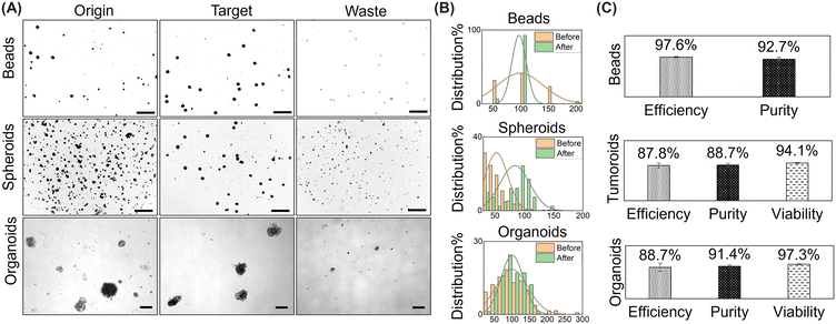
To address the issue of high heterogeneity in tumor organoid culture, we have proposed an intelligent organoid sorting system based on real-time imaging. The system integrates high-speed microscopy with mixed software and hardware chips to achieve real-time data acquisition, processing, decision-making, and execution. Image processing algorithms are used to classify organoids and confirm their sizes. Portable pressure pumps are then used to control elastic microvalves for fluid deflection, which is a very gentle way to handle organoids. The elastic microvalves consist of a pneumatic PDMS membrane sandwiched between two channels. These valves offer millisecond response times and no leakage or dead volume and are easy to manufacture.23,24 We conducted classification experiments on polystyrene beads, F9 tumor cell spheroids, and patient-derived tumor organoids. The device achieved a separation efficiency of over 97% and purity of over 92% for polystyrene beads, a separation efficiency of over 87%, purity of over 88% and viability of over 94% for F9 tumor cell spheroids, and a separation efficiency of over 88%, purity of over 91% and viability of over 97% for organoids. The sorting throughput was 800 per hour, meeting the requirements for clinical organoid medicine.
Experimental design
Device design
The objective of the research is to develop an automated microfluidic system for organoid classification, utilizing optical imaging and real-time classification algorithms to identify organoids within specific size ranges. Furthermore, selected organoids can be separated and transported to the outlet using on-chip valves. As illustrated in Fig. 1, the design of the sorting system comprises three components: a microfluidic chip, actuation elements, and control algorithms. Organoids in the solution are initially transported into the chip via inlet 1 using a syringe pump and are subsequently maintained in the middle section by the sheath flow from the liquids in inlet 2 and inlet 3. The organoids then pass through the region of interest, also known as the detection area, where a high-speed camera captures images in real time and transmits the image data to a Python program on a computer. The Python program calls the real-time image recognition algorithm in OpenCV to classify the captured images into signal 1 for organoids that meet the requirements and signal 0 for the other organoids. The analysis data are then transmitted via a serial port to the Arduino actuating components (as seen in Fig. S1†). Upon receiving the 0/1 signal, Arduino controls the opening and closing of pneumatic valves through the circuit board and commands the on/off of the pneumatic pump. When one side of the pneumatic valve is open and the other is closed, a deflection flow is formed at the intersection, directing organoids to flow into different outlets. The overall classification logic is depicted in Fig. S2.†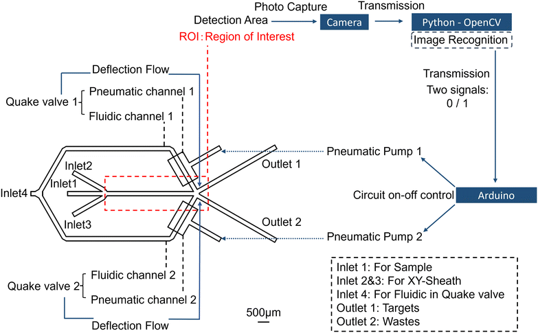 | ||
| Fig. 1 Layout of the microfluidic sorting system: microfluidic chip, actuation components and control algorithms. Scale bar: 500 μm. | ||
Theory and mechanism
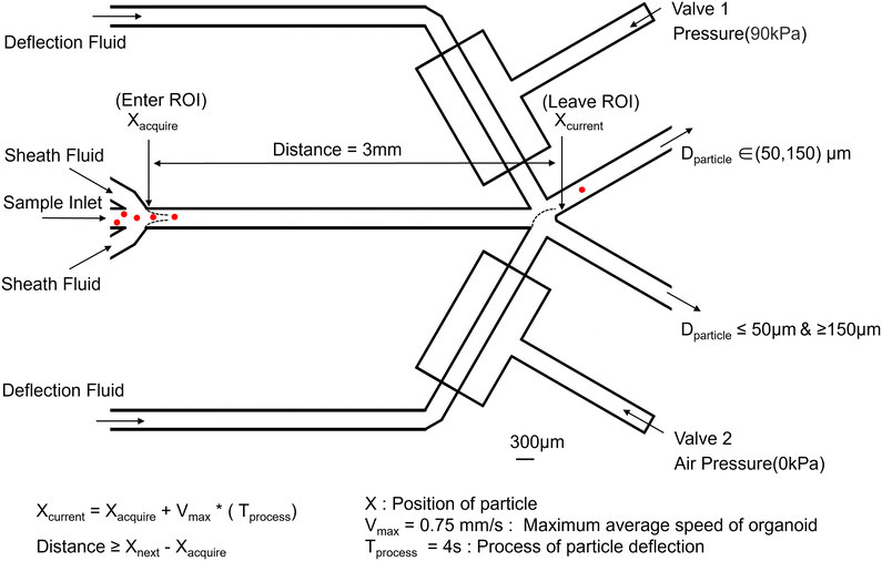
In order to fulfil the design requirements, it is essential to obtain appropriate organoids with diameters ranging from 50 to 150 μm. It has been stated in the literature that the size distribution of most types of tumor organoids cultured through conventional methods (in Matrigel) centers at around 100 μm.25 The average diameter of organoids needs to be set at 50 μm as the minimum requirement for drug screening.26 In instances where the organoids grow exceptionally large, intrinsic cellular apoptosis occurs,27 and the quantity of organoids exceeding a diameter of 150 μm is notably small within 3 days of culture for drug screening. Consequently, based on the actual size distribution of patient derived organoids in the clinic, the requisite size range for screening organoids has been delineated between 50 and 150 μm. The device must prevent organoids from adhering to the channels, and high reliability and repeatability are crucial objectives for the sorting operation. Organoids should pass through the identification area individually, with sufficient spacing between consecutive organoids to account for delays associated with image processing, classification, and the response time of electromechanical components.Fig. 2 illustrates the system's operation as selected organoids pass through the region of interest (ROI). Valve 1 is closed by a pressure of 90 kPa, resulting in a flow rate of 0 in the above channel. Concurrently, the pressure pump on the bottom remains off, maintaining a flow rate of 4 mL h−1 in the channel. Both the middle sample inlet and sheath channel exhibit flow rates of 0.2 mL h−1. Based on the fluid distribution, organoids will flow out from the right(up) outlet, accompanied by the fluid directed to the right(up). Fig. 2 also demonstrates the process of determining the length of the ROI. Upon capturing the image when the target enters the ROI, the system status begins to change, and the total running time is 4 seconds. The length of the ROI must be greater than the distance the target has travelled. Thus, the distance between X_acquire and X_current is set to 3 mm.
Relaxation time is always needed for the transition of deflection flow, particularly in high-viscosity fluids where the pneumatic valve necessitates an extended relaxation period to return to a stable state, which significantly influences the switching speed of the valve.28 Utilizing a dual-microvalve system, where one microvalve closes simultaneously as the other opens, can effectively shorten the relaxation time, thus reducing the duration of deflection and enhancing throughput. From a clinical application perspective, organoids smaller than 50 μm and larger than 150 μm are unsuitable for direct clinical use and require digestion, dissociation, and recultivation before further utilization. Therefore, we have consolidated the organoids smaller than 50 μm and larger than 150 μm into a single outlet.
Materials and methods
Fabrication of microdevices
The microchip consists of a dual-layer channel configuration. The upper layer features a fluid channel equipped with a sheath flow structure designed for sample focusing, which leads into a Y-shaped junction utilized for sorting purposes. The lower layer features a control channel for managing integrated pumps and valves. The fluid channel measures 300 μm in width and 270 μm in height. Given that organoid diameters range from 30 to 200 μm, the channel height of 270 μm ensures smooth organoid movement without obstruction from channel walls.The chip's mold was created using standard multilayer lithography technology. The control and fluid layers of the microchip were constructed using two distinct molds. The fluid layer mold consists of two parts: a channel formed from reflow AZ50XT photoresist with rounded cross-sectional features and a height of 30 μm, and an organoid passage channel mold made from SU8-2100 photoresist with a height of 270 μm. The control layer mold was prepared using SU8-3050, yielding a channel height of 80 μm.
The layer-by-layer assembled microchip was entirely fabricated using PDMS. The silanized mold was filled with a mixed PDMS prepolymer, which was then degassed and cured. Upon cooling, the PDMS replica was extracted from the mold and trimmed to the required shape. Inspection holes were punched out to serve as fluid channel connections. The control layer film preparation process involved diluting 20![[thin space (1/6-em)]](https://www.rsc.org/images/entities/char_2009.gif) :
:![[thin space (1/6-em)]](https://www.rsc.org/images/entities/char_2009.gif) 1 PDMS with 40 g hexane, mixing and removing bubbles, and then spin-coating it onto a glass slide to achieve a thickness of 10 μm. The mixture was left to stand for 30 minutes to allow the surface to smooth out before being cured on an 80 °C hot plate for another 30 minutes. Finally, the fluid channel part, organoid channel part, and membrane were assembled using plasma treatment to form the chip. The entire fabrication process is depicted in Fig. 3.
1 PDMS with 40 g hexane, mixing and removing bubbles, and then spin-coating it onto a glass slide to achieve a thickness of 10 μm. The mixture was left to stand for 30 minutes to allow the surface to smooth out before being cured on an 80 °C hot plate for another 30 minutes. Finally, the fluid channel part, organoid channel part, and membrane were assembled using plasma treatment to form the chip. The entire fabrication process is depicted in Fig. 3.
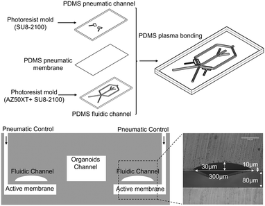 | ||
| Fig. 3 Fabrication process of the microfluidic chip and schematic diagram of the cross-section of a microfluidic valve geometry. | ||
Sample preparation
Upon receiving the organoids supplied by the hospital, digest the surrounding Matrigel using 3–5 mL of PBS containing 10 mM EDTA and incubate on ice for 30 minutes. Subsequently, centrifuge the organoids in PBS, discard the supernatant, and resuspend them in 1% sodium carboxymethylcellulose. Finally, transfer the organoid suspension into a 1 mL syringe and connect it to the organoid sorting system. The function of sodium carboxymethyl cellulose is to prevent the rapid sedimentation of organoids during experimental procedures. The existing literature has shown the application of high-viscosity solutions (methylcellulose) in microfluidic channels to restrict the movement of targets through high-viscosity confinement.29 The anti-sedimentation mechanism of sodium carboxymethyl cellulose is attributed to its high-viscosity properties; particles are driven to the channel centerline under the control of fluid viscoelasticity.30 Consequently, this facilitates the organoids' movement along with the fluid flow in the channel, rather than settling too rapidly or adhering to the channel walls.Detection and sorting programming
In Python, library functions are called directly, and parameters can be easily modified to achieve different objectives. The image recognition process for organoids consists of several steps, including image reading, grayscale processing, noise reduction, erosion, dilation, edge detection, contour drawing, length and width calculations, and actual size determination based on the pixel size. A portion of the entire image recognition process for an organoid is illustrated in Fig. S3.† The most critical components are noise reduction and edge detection. While various methods can accomplish these functions, each approach has its optimal application. We have fine-tuned each parameter to obtain the best results.Results and discussion
Organoid sorting
Fig. 4 illustrates the classification results of beads, spheroids and organoids, and the actual classification process is shown in the video. When the diameter of the beads/spheroids/organoids is recognized to be between 50 μm and 150 μm, the target one is marked by a red box and directed to the target outlet through the deflected flow. Conversely, when the diameter of the tumoroid/organoid is less than 50 μm or larger than 150 μm, they are directed to the waste outlet along with the deflected flow. In image processing, the organoid is processed through a series of algorithms into a shape with smooth edges, as depicted in Fig. S3.† Subsequently, the length and width of the largest bounding rectangle of the processed image are determined. This implies that the measured diameter reported in the manuscript represents the maximum size of the organoid.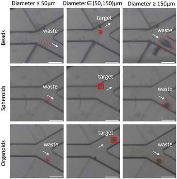 | ||
| Fig. 4 Image of captured beads, spheroids and organoids in the junction of the ROI. Scale bar: 300 μm; sorting performance metrics in 200 μL h−1; bead/spheroid/organoid density is 1000 ml−1. | ||
The performance metrics for devices that separate biological particles are defined in the following manner: efficiency measures the sorting system's effectiveness and is determined as the ratio of the number of target organoids in the desired area to the number of total target organoids in the sample. Purity is measured by the ratio of target organoids within the desired area to the total organoids present in that area. Viability is measured by the ratio of number of live cells after sorting to the number of live cells before sorting. Throughput is defined by the volume of the sample that the device processes per unit of time, and the units can vary significantly depending on the application.
Sorting performance:
 | (1) |
 | (2) |
 | (3) |
| Throughput = 1 hour/(Tprocess) × Efficiency | (4) |
Conclusions
In this study, the system achieves real-time data acquisition, processing, decision-making, and execution through a high-speed microscope and a mixed software and hardware integrated chip. While image-based detection methods are constrained by slow acquisition speeds, they offer unique advantages: external devices (microscopes and cameras) are standard configurations in most laboratories; iterative optimization of image processing algorithms can improve image processing quality and obtain accurate morphological information; detection algorithms can be readily adapted to different target materials without the need to redesign mechanical components. In microfluidic platforms, there are various mechanisms for fluid control, such as controlling the flow rate using syringe pumps and regulating pneumatic pressure with pressure pumps. However, the separation of organoids necessitates quick flow control response, which constrains the use of syringe pumps due to their lengthy relaxation times. Electric field control is also limited in large-sized target material control due to the risk of high electric field damage to organoids.31 In this study, we chose to use a portable pneumatic pump to control the microfabricated elastic microvalves to achieve fluid deflection. The elastic microvalves consist of a polydimethylsiloxane (PDMS) membrane sandwiched between two channels. These valves provide millisecond response times and no leakage or dead volume and are easy to manufacture.The primary reason for low throughput is the process time. As illustrated in Fig. 2, the process time for particle deflection is 4 seconds. The principal factors influencing the process time include the switching speed of the valve, as well as the speed of image acquisition and image processing. To alleviate the issue of low valve switching speed, future enhancements could involve changing the PDMS quake valve with a faster-switching microvalve for pneumatic control of microfluidic systems, such as an electromagnetic microvalve. However, these modifications might substantially increase the complexity and cost of the system. The speed of image processing is only 30 ms, which is minuscule compared to the valve's 4 second switching time. Yet, once the pneumatic valve is replaced with a faster-switching microvalve—where the switching speed could be just a few milliseconds—enhancing the speed of image processing becomes crucial. Improvements could include utilizing a more powerful computing platform and simplifying the image processing algorithms to reduce processing time. During the sorting process, the average frame rate is 30 fps. Further improvements to enhance system throughput could involve migrating the sorting software to a higher speed camera platform to increase the frame rate, thereby shortening the image acquisition time. This would also help minimize motion artifacts formed by the rapid movement of organoids in the channel. The presence of motion artifacts can interfere with the image recognition program's accuracy in calculating organoid size; reducing these artifacts leads to more precise size determinations.
In conclusion, we presented an integrated microfluidic device that employs real-time image processing algorithms to identify and sort appropriately-sized organoids using deflected fluid controlled by microvalves. This innovative device is fully automated, cost-effective, and easily implemented in academic research settings. As a morphology-activated organoid sorting system, it offers numerous advantages such as portability, label-free operation, high sample resolution, gentle handling of organoids, and organoid capture within the device. In collaboration with tumor research institutions, this device has achieved a separation efficiency of over 97% and purity of over 92% for polystyrene beads, a separation efficiency of over 87%, purity of over 88% and viability of over 94% for F9 tumor cell spheroids, and a separation efficiency of over 88%, purity of over 91% and viability of over 97% for organoids, thereby satisfying the requirements for clinical organoid medicinal applications. However, due to the considerable size and high viscosity of organoids, the channel size of this device is relatively large, resulting in a modest throughput of 800 organoids per hour.
Data availability
The data supporting this article have been included as part of the ESI.† The raw data produced and analyzed in this study are available from the corresponding author upon reasonable request. All data supporting the results of this study can be accessed in accordance with the journal's data-sharing policies.Author contributions
Xingyang Yan designed the whole device, performed the research, analysed the data, and prepared the initial draft. Deng Tan, Danyu Li and Zhenghao Wang constructed F9 spheroids. Lei Yu helped prepare organoids for sorting experiments. Weiren Huang and Hongkai Wu generated the idea for this work, supervised the work, coordinated the collaborations, and contributed to manuscript writing.Conflicts of interest
There are no conflicts to declare.Acknowledgements
This work was financially supported by Hong Kong Research Grant Council (#16309920, #16300622, #16309421 and #16300323), Hong Kong ITC (Grant ITC-CNERC14SC01), Guangdong Basic and Applied Basic Research Foundation (2022B1515130010, 2024A1515011810 and 2022A1515110675), and HKUST OKT (#BGF.029.2024).Notes and references
- Z. Zhao, X. Chen, A. M. Dowbaj, A. Sljukic, K. Bratlie, L. Lin, E. L. S. Fong, G. M. Balachander, Z. Chen, A. Soragni, M. Huch, Y. A. Zeng, Q. Wang and H. Yu, Nat. Rev. Methods Primers, 2022, 2, 1–21 CrossRef PubMed.
- V. Veninga and E. E. Voest, Cancer Cell, 2021, 39, 1190–1201 CrossRef CAS PubMed.
- E. Garreta, R. D. Kamm, S. M. C. de S. Lopes, M. A. Lancaster, R. Weiss, X. Trepat, I. Hyun and N. Montserrat, Nat. Mater., 2021, 20, 145–155 CrossRef CAS PubMed.
- T. Takebe and J. M. Wells, Science, 2019, 364, 956–959 CrossRef CAS PubMed.
- M. Hofer and M. P. Lutolf, Nat. Rev. Mater., 2021, 6, 402–420 CrossRef CAS PubMed.
- P. Sajeesh and A. K. Sen, Microfluid. Nanofluid., 2014, 17, 1–52 CrossRef.
- Y. Shen, Y. Yalikun and Y. Tanaka, Sens. Actuators, B, 2019, 282, 268–281 CrossRef CAS.
- L. R. Huang, E. C. Cox, R. H. Austin and J. C. Sturm, Science, 2004, 304, 987–990 CrossRef CAS PubMed.
- P. Chandna and V. Gundabala, Microfluid. Nanofluid., 2021, 25, 6 CrossRef CAS.
- J. A. Hernández-Castro, K. Li, J. Daoud, D. Juncker and T. Veres, Lab Chip, 2019, 19, 589–597 RSC.
- X. Xu, X. Huang, J. Sun, R. Wang, J. Yao, W. Han, M. Wei, J. Chen, J. Guo, L. Sun and M. Yin, Analyst, 2021, 146, 7070–7086 RSC.
- S. Sofela, S. Sahloul, M. Rafeie, T. Kwon, J. Han, M. E. Warkiani and Y.-A. Song, Lab Chip, 2018, 18, 679–687 RSC.
- A. Dalili, E. Samiei and M. Hoorfar, Analyst, 2018, 144, 87–113 RSC.
- A. Esan, F. Vanholsbeeck, S. Swift and C. M. McGoverin, Biomicrofluidics, 2023, 17, 044104 CrossRef CAS PubMed.
- D. Schraivogel, T. M. Kuhn, B. Rauscher, M. Rodríguez-Martínez, M. Paulsen, K. Owsley, A. Middlebrook, C. Tischer, B. Ramasz, D. Ordoñez-Rueda, M. Dees, S. Cuylen-Haering, E. Diebold and L. M. Steinmetz, Science, 2022, 375, 315–320 CrossRef CAS PubMed.
- M. M. Wang, E. Tu, D. E. Raymond, J. M. Yang, H. Zhang, N. Hagen, B. Dees, E. M. Mercer, A. H. Forster, I. Kariv, P. J. Marchand and W. F. Butler, Nat. Biotechnol., 2005, 23, 83–87 CrossRef CAS PubMed.
- V. Kumar and P. Rezai, Biomed. Microdevices, 2017, 19, 39 CrossRef PubMed.
- X. Wang, Y. Xin, L. Ren, Z. Sun, P. Zhu, Y. Ji, C. Li, J. Xu and B. Ma, Sci. Adv., 2020, 6, eabb3521 CrossRef CAS PubMed.
- X. Duan, X. Zheng, Z. Liu, T. Dong, Y. Luo, W. Yan, C. Wang and C. Song, Anal. Chem., 2024, 96, 1301–1309 CrossRef CAS PubMed.
- T. Franke, S. Braunmüller, L. Schmid, A. Wixforth and D. A. Weitz, Lab Chip, 2010, 10, 789–794 RSC.
- C. W. S. Iv, C. D. Reyes and G. P. López, Lab Chip, 2015, 15, 1230–1249 RSC.
- M. Sivaramakrishnan, R. Kothandan, D. K. Govindarajan, Y. Meganathan and K. Kandaswamy, Curr. Opin. Biomed. Eng., 2020, 13, 60–68 CrossRef.
- M. A. Unger, H.-P. Chou, T. Thorsen, A. Scherer and S. R. Quake, Science, 2000, 288, 113–116 CrossRef CAS PubMed.
- A. K. Au, H. Lai, B. R. Utela and A. Folch, Micromachines, 2011, 2, 179–220 CrossRef.
- J. H. Chen, X. P. Chu, J. T. Zhang, Q. Nie, W. F. Tang, J. Su, H. H. Yan, H. P. Zheng, Z. X. Chen, X. Chen, M. M. Song, X. Yi, P. S. Li, Y. F. Guan, G. Li, C. X. Deng, R. Rosell, Y. L. Wu and W. Z. Zhong, Thorac. Cancer, 2020, 11, 2279–2290 CrossRef CAS PubMed.
- Y. Yao, X. Xu, L. Yang, J. Zhu, J. Wan, L. Shen, F. Xia, G. Fu, Y. Deng, M. Pan, Q. Guo, X. Gao, Y. Li, X. Rao, Y. Zhou, L. Liang, Y. Wang, J. Zhang, H. Zhang, G. Li, L. Zhang, J. Peng, S. Cai, C. Hu, J. Gao, H. Clevers, Z. Zhang and G. Hua, Cell Stem Cell, 2020, 26, 17–26.e6 CrossRef CAS PubMed.
- H. Yang, J. Cheng, H. Zhuang, H. Xu, Y. Wang, T. Zhang, Y. Yang, H. Qian, Y. Lu, F. Han, L. Cao, N. Yang, R. Liu, X. Yang, J. Zhang, J. Wu and N. Zhang, Cancer Cell, 2024, 42, 535–551.e8 CrossRef CAS PubMed.
- G. Choi, R. Nouri, L. Zarzar and W. Guan, Microsyst. Nanoeng., 2020, 6, 11 CrossRef CAS PubMed.
- L. R. Blauch, Y. Gai, J. W. Khor, P. Sood, W. F. Marshall and S. K. Y. Tang, Proc. Natl. Acad. Sci. U. S. A., 2017, 114, 7283–7288 CrossRef CAS PubMed.
- J. Zhou and I. Papautsky, Microsyst. Nanoeng., 2020, 6, 113 CrossRef CAS PubMed.
- I. Turcan and M. A. Olariu, ACS Comb. Sci., 2020, 22, 554–578 CrossRef CAS PubMed.
Footnote |
| † Electronic supplementary information (ESI) available. See DOI: https://doi.org/10.1039/d4lc00746h |
| This journal is © The Royal Society of Chemistry 2025 |

