Preparation of three-dimensional chromium oxide porous single crystals templated by SBA-15
Kake
Zhu
a,
Bin
Yue
a,
Wuzong
Zhou
*b and
Heyong
He
*a
aShanghai Key Laboratory of Molecular Catalysis and Innovative Materials, Department of Chemistry, Fudan University, Shanghai 200433, P. R. China. E-mail: heyonghe@fudan.edu.cn
bSchool of Chemistry, St. Andrews University, St. Andrews, Fife, UK KY16 9ST. E-mail: wzhou@st-andrews.ac.uk
First published on 28th November 2002
Abstract
Three-dimensional porous chromium oxide single crystals have been prepared by aminosilylation of the surface silanols of the template, SBA-15, anchoring of dichromic acid to the grafted amine groups, thermal decomposition of inorganic and organic compounds, and removal of the silica framework with HF.
Transition metal oxides form a large family of materials which find utilities in areas of catalysis, superconductivity, colossal magnetoresistance, piezoelectricity, etc. Their nanosized forms differ greatly in many properties from the bulk materials.1 The most common nanosized materials are nanoparticles.2 Generally, one-dimensional (1D) extendedness of nanoparticles leads to nanorods or nanowires,3 while the two-dimensional extendedness results in ultra-thin films.4 A three-dimensional (3D) extension of nanoparticles gives normal bulk crystals and the characteristic properties of the nanoscale solids is lost. Recently, several new methodologies have been developed to use mesoporous silica channels or carbon nanotubes as nanoscale reactors for preparing 1D nanorods or nanowires of metals and semiconductors.5–8 3D replicas of noble metal and carbon have also been obtained when the templates with 3D pore structure were used as moulds.9–12 We report here the fabrication of 3D-porous single crystals (3D-PSC) of chromium oxides templated by SBA-15. The structure of the products is an array of hexagonally ordered nanorods linked by nanosized bridges to form a 3D open framework. The products also can be regarded as single crystals that are carved with a honeycomb pattern.
SBA-15 was synthesized according to the reported procedures.13 The obtained material has amorphous silica walls and hexagonally arranged straight channels with a unit cell parameter of about 12 nm, a pore volume of 1.25 cm3 g−1, a mean pore diameter of 7.8 nm and a surface area of 674 m2 g−1. The specimen was then aminosilylated using γ-aminopropyltriethoxysilane (APTS) to form a functionalized template (APTS/SBA-15).14 Chromium in the form of H2Cr2O7 was introduced into the mesopores by stirring a 100 ml solution containing 10% (wt.) K2Cr2O7 with 1 g of APTS/SBA-15 at pH = 1.5 adjusted with HCl. After stirring for 12 h, the mixture was filtered off, washed with water three times to remove the remaining unanchored chromium species, and dried at 95 °C for 5 h. The obtained sample (H2Cr2O7/APTS/SBA-15) was then undergoing a programmed thermal decomposition of the inorganic and organic compounds in order to grow Cr2O3 single crystals inside the SBA-15 channels. The product is denoted as Cr2O3/SBA-15.
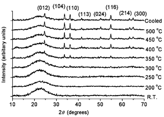
The decomposition was monitored by TG–DTA and in situ XRD. The TG curve displays a weight loss of 2.2% in the region of 190–380 °C in succession, which is due to oxidation of organics and decomposition of H2Cr2O7. The mass becomes essentially constant above 380 °C. The DTA curve also exhibits a broad exothermic peak ranging from 200 to 390 °C, which is consistent with the TG results. In situ XRD patterns (Fig. 1) indicate that crystalline Cr2O3 formed above 350 °C. XRD patterns (not given) show that the structure of the host SBA-15 remains in APTS/SBA-15 and Cr2O3/SBA-15, although the d100 values of SBA-15, APTS/SBA-15 and Cr2O3/SBA-15 are 10.0, 9.8, and 8.8 nm, respectively, indicating the structural shrink during the treatments.
 | ||
| Fig. 1 In situ XRD patterns during the heat treatment of H2Cr2O7/APTS/SBA-15. The peaks appeared above 350 °C can be indexed onto the unit cell of rhombohedral Cr2O3 with a = 0.4959 and c = 1.359 nm. | ||
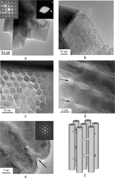
The obtained Cr2O3/SBA-15 was further treated in a 10% HF solution in order to dissolve the silica framework. After several cycles of dissolution and centrifugalization, the final green crystalline Cr2O3 specimen was recovered by washing with water. Fig. 2(a) is a low-magnification image of the silica-free 3D-PSC Cr2O3. It is obvious that both the particle size and morphology of the original SBA-15 specimen have been maintained. Energy dispersive X-ray spectra (EDS) from the particles show only the emission lines from Cr and O, and no Si is detectable. Selected area electron diffraction (SAED) from these particles (inset 1 in Fig. 2(a)) shows the nature of single crystal of rhombohedral Cr2O3 (a = 0.495 and c = 1.37 nm) when viewed down the [2-201] zone axis instead of polycrystalline phases from which diffraction rings consisting of many diffraction spots are normally observed. Enlarging the SAED pattern by increasing the camera length, another set of one-dimensional diffraction spots is just visible (inset 2 in Fig. 2(a)). corresponding to a d-spacings of 3 nm that are comparable to the (220) reflections of the parent SBA-15 structure. Fig. 2(b) is an enlarged TEM image of a 3D-PSC Cr2O3 particle showing that the particle consists of an array of nanorods. The diameter of the nanorods is ca. 8 nm and the hollow space between the nanorods is visible as the white fringes. It is obvious that the diffraction pattern of the inset 2 of Fig. 2(a) is due to the ordering of these nanorods. Fig. 2(c) is a cross-section TEM image of the nanorods. Compared to the porous structure of SBA-15, the nanorods with hexagonal pattern are relatively less ordered, leading to less number of diffraction spots (inset 2 in Fig. 2(a)). The difference of the structural images between SBA-15 and 3D-PSC Cr2O3 is that they have reversed image contrast patterns. In 3D-PSC Cr2O3 the dark disks in the image correspond to the Cr2O3 nanorods and the space between them gives light image contrast, indicating empty space or a very low density of matter.
 | ||
| Fig. 2 (a)–(c) TEM images of the 3D-PSC Cr2O3. (a) Low-magnification image. From the same particle with different camera lengths, inset 1 and inset 2 show the nature of single crystal of rhombohedral Cr2O3 and SBA-15-like hexagonal unit cell. (b) Higher magnification showing the ordering of the Cr2O3 nanorods. (c) TEM image showing the cross section of the hexagonally ordered nanorods. (d), (e) HRTEM images of 3D-PSC Cr2O3. Two arrows in (d) indicate the bridges. The distance between two fringes in (d) is ca. 0.35 nm corresponding to the d-spacing of (012) in rhombohedral Cr2O3. The inset in (e) is the corresponding SAED pattern and the arrow indicates a channel in between the nanorods of Cr2O3. (f) Schematic drawing of the structure of 3D-PSC Cr2O3. | ||
HRTEM images (Fig. 2(d) and (e)) reveal local structural features. First, an examination of the nanorods in the same particle shows that the crystal structures of all nanorods are uniformly orientated. Second, the rhombohedral Cr2O3 phase is confirmed in an agreement with the XRD results. Finally, all the nanorods are connected three dimensionally by some bridges, which also have the same orientation with the nanorods, so that the whole particle becomes a 3D-porous single crystal (Fig. 2(f)). The shape of the pores in 3D-PSC Cr2O3 are grid-like slits with the width of about 2 to 3 nm.
N2 adsorption–desorption measurement at 77 K shows 3D-PSC Cr2O3 has a BET surface area of 58.1 m2 g−1, as well as a pore volume of 0.143 cm3 g−1 and an average pore size of 3.4 nm calculated from the desorption branch of the isotherm using the BJH method. Although we are aware that the novel porous structure of the 3D-PSC Cr2O3 may affect the accuracy of these porosity data significantly, the results still indicate the mesoporosity in the sample which is consistent with the TEM observations.
According to the existing experimental evidence, it is unlikely that there is only one seed developed in each SBA-15 particle where the crystal growth starts. In other word, the crystallization must take place in different channels simultaneously in a particle, forming polycrystalline nanorods. The chance for all the microcrystals in different channels to have exactly the same orientation is almost zero. Consequently, the polycrystalline nanorods present as an intermediate phase during the crystal growth. Such individual nanorods were indeed observed occasionally in the final products. These polycrystalline nanorods then join together by some bridges and recrystallized into a single crystal. According to our observation, all the particles of Cr2O3 are porous single crystals. However, the orientations of the crystals in relation to the nanorod direction can be different in different particles as seen in Fig. 2(d) and (e). Although the nanorods are almost replicas of mesopores in SBA-15, it is not necessary to conclude that the diameter of the bridges is also similar to the size of possibly existing inter-channel micropores in the SBA-15 template. These micropores might be much smaller and the growing crystals inside these channels may “push” the surrounding silica, resulting in a larger space for the formation of the bridges. A similar phenomenon was discovered when silver nanowires were produced from some microporous zeolites.15 It is also noticeable that the diameter of the nanorods exceeds the pore diameter of SBA-15, indicating that the nanorods would continue to grow and decompose the surrounding silica framework. It is even possible to form nonporous large single crystals when the temperature of the crystallization is too high and/or the time of the crystallization is too long. This phenomenon implies that the space between the nanorods may be tuned by controlling the experimental conditions.
The present work demonstrates that construction of 3D-porous single crystal of transition metal oxides can be achieved by using SBA-15 as a template. The products are believed to be mechanically much stronger than amorphous or polycrystalline metal oxide mesoporous materials. Therefore, this kind of materials have potential to be used as self-supported catalysts with a high activity due to their large surface area and shape selectivity. Further investigations on growth of other 3D-PSC metal oxides and on their physico-chemical properties are being carried out in these laboratories.
H. H. acknowledges the Ministry of Education of China and NSFC for financial support (grant No. 20005310). B. Y. acknowledges NSFC for financial support (grant No. 20171013). W. Z. wishes to thank the Scottish High Education Funding Council and Chinese Academy Sciences for financial support.
Notes and references
- E. Rosencher, A. Fiore, B. Vinter, V. Berger, P. Bios and J. Nagle, Science, 1996, 271, 168 CAS.
- H. Schmidt, G. Jonschker, S. Goedicke and M. Mennig, J. Sol–Gel Sci. Technol., 2000, 19, 39 Search PubMed.
- J. C Johnson, H. Q. Yan, R. D. Schaller, P. B. Petersen, P. D. Yang and R. J. Saykally, Nano Lett., 2002, 2, 279 CrossRef.
- W. Weiss and W. Ranke, Prog. Surf. Sci., 2002, 70, 1 CrossRef CAS.
- Y. J. Han, J. M. Kim and G. D. Stucky, Chem. Mater., 2000, 12, 2068 CrossRef CAS.
- M. H. Huang, A. Choudrey and P. D. Yang, Chem. Commun., 2000, 1063 RSC.
- C. H. Ko and R. Ryoo, Chem. Commun., 1996, 2467 RSC.
- Z. Liu, Y. Sakamoto, T. Ohsuna, K. Hiraga, O. Terasaki, C. H. Ko, H. J. Shin and R. Ryoo, Angew. Chem., Int. Ed., 2000, 30, 3107 CrossRef CAS.
- S. Inagaki, S. Guan, T. Ohsuna and O. Terasaki, Nature, 2002, 416, 304 CrossRef CAS.
- Z. Liu, O. Terasaki, T. Ohsuna, K. Hiraga, H. J. Shin and R. Ryoo, Chem. Phys. Chem., 2001, 4, 229 CrossRef CAS.
- R. Ryoo, C. H. Ko, M. Kruk, V. Antochshuk and M. Jaroniec, J. Phys. Chem. B, 2000, 104, 11465 CrossRef CAS.
- H. J. Shin, R. Ryoo, M. Kruk and M. Jaroniec, Chem. Commun., 2001, 349 RSC.
- D. Zhao, J. Feng, Q. Huo, N. Melosh, G. H. Fredrickson, B. F. Chmelka and G. D. Stucky, Science, 1998, 279, 548 CrossRef CAS.
- W. Kaleta and K. Nowinska, Chem. Commun., 2001, 535 RSC.
- W. Zhou, M. J. Edmondson, P. A. Anderson and P. P. Edwards, Inst. Phys. Conf. Ser., 2001, 168, 397 Search PubMed.
| This journal is © The Royal Society of Chemistry 2003 |
