Design and fabrication of an integrated cell processor for single embryo cell manipulation
Jungyul
Park
a,
Seng-Hwan
Jung
a,
Young-Ho
Kim
a,
Byungkyu
Kim
*a,
Seung-Ki
Lee
b and
Jong-Oh
Park
a
aMicrosystem Research Center, Korea Institute of Science and Technology, P.O.BOX 131, Cheongryang, Seoul 130-650, Korea. E-mail: sortpark@kist.re.kr; jung95@kist.re.kr; elf1120@kist.re.kr; bkim@kist.re.kr; jop@kist.re.kr; Fax: +82-2-958-6910; Tel: +82-2-958-5613
bSchool of Electrical, Electronic and Computer Engineering, Dankook University, San 8, Hannam-dong, Yongsan-ku, Seoul 140-714, Korea. E-mail: skilee@dku.edu; Fax: +82-2-795-8771; Tel: +82-2-709-2785
First published on 7th October 2004
Abstract
This paper presents an integrated cell processor for the automatic handling of individual embryo cells. The integrated processor can perform various functions such as cell transport, isolation, orientation, and immobilization. These functions are indispensable and frequently used for the manipulation of single cells, but can only be carried out by a skillful operator. The purpose of this study was the integration and automation of these functions for effective cell manipulation, using a MEMS approach. The isolation of a cell was performed using polypyrrole (PPy) valves in a microchannel into which cells were transported. The orientation of cells was controlled by electrorotation (ER), and the target cell was immobilized by suction from a microhole. All of these functions were seamlessly realized on a single chip. Excellent experimental results with mouse (B6CBA) embryo cells showed that this device could substitute for routine and cumbersome manual work. It is expected that the integrated chip will contribute significantly to faster and more reliable manipulation of cells.
Introduction
Recently, the characterization and manipulation of individual embryo cells has become a challenging issue in biomedical applications such as cloning, gene expression analysis, and cell replacement therapy (CRT).1–4 Those techniques are essential in the agricultural industry,5 individual-cell-based diagnosis, and pharmaceutical testing.6 In spite of great interest in the manipulation of single cells, most cell manipulation tasks, such as gene injection, in vitro fertilization (IVF), and intracytoplasmic sperm injection (ICSI), are carried out manually by a skilful operator using a microscope.2–4 It usually takes more than a year for an operator to be able to perform embryo cell manipulation tasks reliably. Nevertheless, the rate of successful manipulations is extremely low. In addition, cells are irregular in shape and easily deformable, and can therefore be seriously damaged during manipulation and treatment.7 Another problem is that classical cell-biology studies based on petri-dish cell culture may not be suitable for the study of single cells.5Previously, we demonstrated a new automated cell manipulation platform using a precision robotic system that can substitute for the manual cell manipulation processes.8 In order to increase operational speed and repeatability, the automated cell manipulation system may include many components; for example, motorized micromanipulators for micropipette positioning, a visual servoing system for cell tracking, and a cell processor to handle individual cells.
This paper is focused on the new design, fabrication, and feasibility evaluation of an on-chip integrated cell processor for single embryo cell manipulation that can substitute for manual manipulation. The cell processor developed can automatically perform four sequential functions, as described in Fig. 1: cell transport, isolation, orientation, and immobilization. Transporting and retaining embryos in a specific region are the essential and fundamental steps of cell manipulation. A glass micropipette is one of the basic tools for such procedures, but the handling procedure using micropipettes is repetitive and can cause damage to cells.5 Our approach employed microfluidic channels and PPy valves to eliminate most of the manual handling steps. Embryos were transported in a microchannel by fluid flow driven by external pressure. Then, a target cell was isolated from the other cells by the actuation of PPy valves.
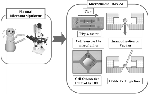 | ||
| Fig. 1 The functions of the cell processor. | ||
The control of individual cell orientation is essential for a high fertilization, cleavage, and survival rate.9 Typically, the orientation of a cell is controlled using a micropipette, requiring expert skills. The cell orientation steps, which should be safe, precise, and easy to control, needed to be automated and we chose electrorotation (ER) to achieve this goal.
Cell immobilization is necessary for stable cell manipulation because of flow disturbances due to micropipette motion. Typically, a pipette holds the cells using suction. In our device, the target embryo cell was immobilized by suction from a microhole. Another important feature of this study is that cell transport, isolation, orientation, and immobilization were realized with a relatively simple design and fabrication process.
Design and manipulation process
We designed an integrated a cell processor for single cell manipulation (Fig. 2). This device has the required functions integrated on one chip. The transport of cells such as red blood cells, yeast, and other small cells through microchannels has been described previously.10–12 In previous work, mammalian embryo cells were used, but only transport was tested.5 Prior to this study, little has been done regarding automation of all the steps in the manipulation of mammalian embryo cells.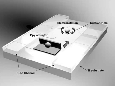 | ||
| Fig. 2 A schematic diagram for the integrated cell processor. | ||
The first step is separation of a single cell from a group of cells. In conventional approaches, a single cell is isolated from a group of homogeneous cells using optical tweezers.13,14 However, the equipment was too expensive and too bulky to be integrated with the chip-scale cell processor. In this study, biocompatible PPy actuators were used as active valves in microchannels, and a single cell was separated with a simple MEMS device. In our approach, embryo cells were placed in a reservoir in the device. The cells were then moved to an injection port by pressure-driven fluid flow in microchannels slightly wider than the cells. As the target cell passed the PPy valve, the valve was closed and the remaining cells were prevented from passing.
The separated target cell was then oriented and immobilized. The cell was moved to the center of the injection port by suction from a microhole. When the cell was brought into the vicinity of the microhole, orientation was controlled by electrorotation (ER) for the optimal angle of the cell injection site. Applications of ER include cell viability determination15 and the detection of surface reactions on microbeads.16 Moreover, since it is generally accepted that it does not lead to any irreversible damage to cells,17 we used it as a method for the cell orientation. In this study, a 250 µm gap was formed between a pair of electrodes, and an AC wave, with a frequency between 300 kHz and 1 MHz and a voltage between 1 and 2 V, was applied. Once the orientation of the cell was adjusted, it was captured and immobilized at the microhole. After cell manipulation tasks using a motorized micromanipulator under a microscope, the treated cell was moved to a collection well connected to the microchannels. The above procedures were repeated until all cells in the reservoir were treated.
Fabrication process
The integrated cell processor was fabricated using standard MEMS fabrication procedures on a 4 inch wafer (500 µm thick <100> Si substrate). Fig. 3 shows a diagram of the fabrication process. First, a 1 µm silicon dioxide layer was deposited by thermal oxidation. Then, the silicon on the reverse side was anisotropically etched using a tetramethylammonium hydroxide (TMAH) solution at 95 °C (Fig. 3(a)) to produce a microhole (35 × 35 µm). The 300 Å Cr and 2000 Å Au layers were e-beam evaporated on the top surface. The Cr/Au layers were then patterned and etched to open a window around the microhole (Fig. 3(b)). These windows were necessary for a releasing step in which differential adhesion was used instead of a sacrificial layer.18 Then, a 2000 Å Au layer was deposited (Fig. 3(c)) and patterned by etching (Fig. 3(d)).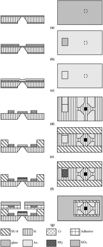 | ||
| Fig. 3 A schematic illustration of the process for the fabrication of the cell processor. | ||
The roles of the Au layer include providing a structural layer in the PPy/Au bilayer, a current collector for the redox reaction that drives the PPy microactuators, and electrodes for ER. Next, a 150 µm thick SU8-100 layer was coated on the Au layer, soft baked, and patterned (Fig. 3(e)). This polymer layer was fabricated to define the microchannel. The cross section of the microchannels is 235 × 150 µm2.
After photopolymerization, we descummed the SU8 structure using reactive ion etching (RIE) (200 W, 50 sccm O2 at 50 mTorr) to remove the thin polymer residue that remains after the developing process. Without this procedure, the PPy was not electrochemically polymerized as intended. PPy microactuators were electrochemically deposited on the Au surface using a potentiostat system with three electrodes (MEMS potentiostat SC, Advanced micromachining tools). The Au layer was covered with a photoresist, and windows for PPy microactuators were opened by photolithography. Then, the PPy layer was automatically patterned at a voltage of 0.7 V vs. Ag/AgCl (Fig. 3(f)). The photoresist was then removed using ethanol. The upper electrodes for ER were patterned on a 500 µm thick Pyrex wafer. An access hole for the micromanipulator was drilled with an NdYag micro-laser (M-2000 Laser, Exitech). Finally, the microfluidic channel was produced by bonding the SU-8 channels to the glass cover with a UV-curable adhesive (Type SK-9, Summers optical) (Fig. 3(g)).
Fig. 4 shows a top view of the fabricated cell processor before the bonding of the glass cover. The size of the device is 35 × 35 mm. It consists of electrodes for ER, an SU-8 channel for the microfludics, and PPy valves, which were installed in the microchannel.
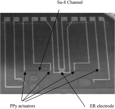 | ||
| Fig. 4 The fabricated cell processor. | ||
Experiment results and discussion
Experimental set-up
Fig. 5 shows the experimental set-up for the cell processor. It consists of two function generators, microsyringes (VIT-FIT, Lambda Co.), a stereomicroscope (Leica), and the integrated cell processor. A multichanneled function generator (Protek 9302) was used to produce the AC sine wave for ER. The neighboring electrodes for ER were driven using a 90°-shifted AC sine wave. In this study, the operating frequency was between 300 kHz and 1 MHz, and the voltage between 1 and 2 V. The second function generator (33250A, Agilent) was used to actuate the PPy valves. The flow in the microchannels and at the microhole was precisely controlled with microsyringes. The cell behavior in the device was monitored with the microscope and digitally recorded with CCD cameras.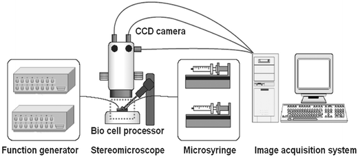 | ||
| Fig. 5 Experimental set-up. | ||
Operation of the integrated cell processor
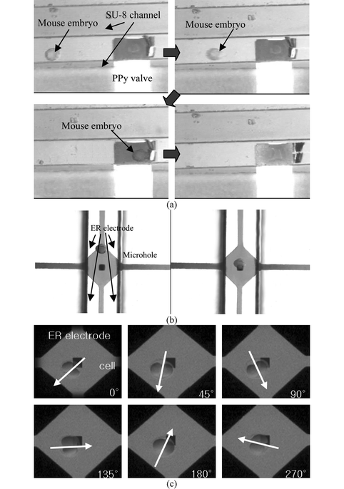 | ||
| Fig. 6 Still images from video clips showing the functions of the cell processor: (a) cell isolation by the actuation of the PPy valve in the microchannel, (b) transporting of the cell to the microhole, and (c) cell orientation by ER. | ||
 | (1) |
 | (2) |
When viscous drag is accounted for, using ER technique, the rotation speed (R(ω)) of a particle is given by22
 | (3) |
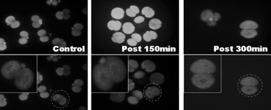 | ||
| Fig. 7 Distribution of mitochondria in mouse (B6CBA) embryo cells after manipulation by ER. | ||
Conclusions
We have demonstrated the feasibility of integrating the whole process of single-cell manipulation on a microfluidic chip. The viability of cells manipulated with the device was successfully demonstrated using mouse (B6CBA) embryo cells. Although dielectrophoretic and optical tweezer techniques for cell isolation might typically be used, we chose a biocompatible-material-based PPy valve, which was compact, cost effective and able to be installed in the channel, and used it to isolate a single cell. In addition, since using the PPy valve means that isolated cells are not exposed to lasers or electric fields, higher cell viability can be achieved after the manipulation process. In consideration of cell viability after ER-based rotation, in this study, a low voltage (1–2 V) was employed to rotate a mouse embryo cell. Under 1–2 V and 400 kHz input conditions, the rotation speed of a cell ranged from 0.1 to 0.7 rad s−1. To verify the cell viability test, the distribution of mitochondria was observed and cells were successfully cultured from the two-cell stage to the blastocyst. The rotation speed was low enough to control orientation automatically, based on visual tracking of cell orientation. Therefore, the device developed will provide an automated platform for manipulating a single cell without losing the viability of the cell.Acknowledgements
The authors wish to thank Professor Sangho Lee of Korea University for culturing cells and many valuable discussions, and Professor Jung-hoon Lee of Seoul National University for a critical review of this article. This work was supported by the 21st Century's Frontier R&D Projects, under contract number MS-02-324-01, sponsored by the Ministry of Science and Technology, Korea.References
- Y. Sun and B. J. Nelson, Int. J. Robot. Res. (IJRR), 2002, 21, 861 Search PubMed.
- K. K. Tan and S. C. Ng, Eng. Sci. Edu. J., 2001, 10, 249 Search PubMed.
- K. Yanagida, H. Katayose, H. Yazawa, Y. Kimura, K. Konnai and A. Sato, Hum. Reprod., 1998, 14, 448 CrossRef.
- T. Nakayama, H. Fujiwara, K. Tastumi, K. Fujita, T. Higuchi and T. Mori, Fertil. Steril., 1998, 69, 784 CrossRef CAS.
- I. Glasgow, H. Zeringue, D. Beebe, S. Choi, J. Lyman, N. Chan and M. Wheeler, IEEE Trans. Biomed. Eng., 2001, 48, 570 CrossRef CAS.
- E. Jager, C. Immerstrand, K. Peterson, K. Magnusson, I. Lundström and O. Inganäs, Biomed. Microdevices, 2002, 4, 177 CrossRef.
- W. Lewis, B. Rosa, L. Peter, M. Elliot, S. Jim and M. J. Thomas, in Principles of development, 2nd edn., Oxford University Press, 2002 Search PubMed.
- B. Kim, D-H. Kim, J-Y. Park, Y-H. Kim, S-J. Kwon, H. Kang and S. Jung, Invited Paper, 2003 IEEE/RSJ International Conference on Intelligent Robots and Systems (IROS 2003), Las Vegas, USA, 27 October–1 November 2003, Workshop: Microrobotics for Biomanipulation Search PubMed.
- L. Westerlaken, F. Helmerhorst, J. Hermans and N. Naaktgeboren, Human Reproduction, 1999, 14, 2565 Search PubMed.
- R. H. Carlson, C. Grabel, S. Chan and R. H. Austin, Biomed. Microdevices, 1998, 1, 39 CrossRef.
- S. Masuda, M. Washizu and T. Nanba, Seventh International Conference on Electrostatic Phenomena (Electrostatics 87), Oxford, UK, 1987, 69 Search PubMed.
- S. A. Kaur and H. S. Virk, Indian J. Pure Appl. Phys., 1995, 33, 350 CAS.
- M. P. Sheetz, in Laser Tweezers in Cell Biology, vol. 55 of Methods in Cell Biology, Academic Press, New York, 1997 Search PubMed.
- J. E. Molloy and M. J. Padgett, Contemp. Phys., 2002, 43, 241 CrossRef CAS.
- J. Gundel, D. Wicher and H. Matthies, Studies Biophys., 1989, 133, 5 Search PubMed.
- C. Hodgson and R. Pethig, Clin. Chem., 1998, 44, 2049 CAS.
- R. Pethig and G. Markx, Trends Biotechnol., 1997, 15, 426 CrossRef CAS.
- E. Smela, O. Inganäs and I. Lundström, Transducers, Stockholm, 1995, 218 Search PubMed.
- J. Ryu, S. Jung, B. Kim, S-K. Lee and J-O. Park, Polymer (Korea) Search PubMed , submitted.
- H. P. Schwan, Electroporation and electrofusion in cell biology, Plenum Press, New York, 1989 Search PubMed.
- U. Zimmerman and G. A. Neil, Electromanipulation of Cells, CRC Press, Boca Raton, 1996 Search PubMed.
- W. Arnold and U. Zimmerman, J. Electrostat., 1988, 21, 151 CrossRef.
- W. Arnold, R. Schmutzler, A. Schmutzler, H. Ven, S. Hasani, D. Krebs and U. Zimmermann, Biochim. Biophys. Acta, 1987, 905, 454 CrossRef CAS.
- D. G. Whittingham, J Reprod. Fertil. Suppl., 1971, 14, 7 Search PubMed.
| This journal is © The Royal Society of Chemistry 2005 |
