A novel high aspect ratio microfluidic design to provide a stable and uniform microenvironment for cell growth in a high throughput mammalian cell culture array
Paul J.
Hung†
,
Philip J.
Lee†
,
Poorya
Sabounchi
,
Nima
Aghdam
,
Robert
Lin
and
Luke P.
Lee
Berkeley Sensor & Actuator Center, Department of Bioengineering, University of California, Berkeley, California, USA. E-mail: lplee@socrates.berkeley.edu; Fax: 1-510-642-5835; Tel: 1-510-642-5855
First published on 2nd November 2004
Abstract
We present a high aspect ratio microfluidic device for culturing cells inside an array of microchambers with continuous perfusion of medium. The device was designed to provide a potential tool for cost-effective and automated cell culture. The single unit of the array consists of a circular microfluidic chamber 40 µm in height surrounded by multiple narrow perfusion channels 2 µm in height. The high aspect ratio (∼20) between the microchamber and the perfusion channels offers advantages such as localization of the cells inside the microchamber as well as creating a uniform microenvironment for cell growth. Finite element methods were used to simulate flow profile and mass transfer of the device. Human carcinoma (HeLa) cells were cultured inside the device with continuous perfusion of medium at 37 °C and was grown to confluency. The microfluidic cell culture array could potentially offer an affordable platform for a wide range of applications in high throughput cell-based screening, bioinformatics, synthetic biology, quantitative cell biology, and systems biology.
A. Introduction
Mammalian cell culture has played a major role in the development of biotechnology, with applications such as screening novel drugs to large scale production of protein pharmaceuticals. Advances have been made in designing automated cell culture systems capable of improving throughput and reducing process cost.1,2 However, the high cost and large size of these systems limits application to large, dedicated research facilities. It is therefore highly desirable to produce a miniaturized, inexpensive platform for “cell-culture-on-a-chip” to make high throughput cell experiments accessible in laboratory, clinical, and field settings. The advantages of microfabrication and microfluidic technologies are ideally suited to address this issue.3 Since living cells are themselves microscale systems, it follows that microfabricated devices can more precisely control the culture environment. The design of a microscale cell culture device presents a number of unique challenges, many of which have been recently discussed.4 Previous demonstrations of cell culture on microfabricated devices include growth of hepatocytes,5,6 lung cells,7 and insect cells8 in both silicon and PDMS substrates. These works validated the biocompatibility, nutrient supply, and growth characteristics of cells within microfabricated devices, but have yet to realize a high throughput array that can replicate the main functionalities of traditional cell culture.Our current work addresses the development of a novel high aspect ratio microfluidic cell culture array capable of providing a stable and uniform microenvironment for cell growth. With heterogeneous integration of a temperature control unit such as an ITO heater, the device could potentially realize an automated cost-effective cell culture platform without the large robotic systems adapted by current practices. The microfluidic device was designed to replicate the major processes in traditional cell culture, making it adaptable to a large number of applications. In this paper, 1 × 5 arrays were used for device characterization to decrease the complexity of data processing and time of optical monitoring. A 10 × 10 array was also fabricated for increased throughput and initial characterization of fluid flow through multiplexed arrays.
B. Device design and fabrication
The microfluidic cell culture system is designed to replicate the major processes applied in standard eukaryotic culture techniques. The current device is capable of providing a closed environment for cell growth and manipulation without the need of an incubator (Fig. 1a). The bonded PDMS culture chambers maintain a sterile environment while permitting gas exchange with the atmosphere. Temperature can be controlled with a transparent ITO heater without hindering monitoring of cells via optical microscopy. While humidity control of the surrounding air would prevent evaporation from the microchannels, we observed that the continuous perfusion of medium was sufficient to prevent the device from drying out. A preliminary study of the flow profile inside a 10 × 10 array was conducted to test the feasibility of splitting and recombining flows in multiplexed arrays (Fig. 1b).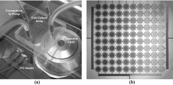 | ||
| Fig. 1 Picture of the proposed system. (a) A 10 × 10 microfluidic cell culture array was bonded to a coverglass and mounted on a transparent ITO heater. Stainless steel plugs with soft tubings connected the device to a syringe pump for fluidic control. Cell growth was monitored using an optical microscope. (b) Stable gradient generation across the columns of the array. A blue and yellow dye was diffusively mixed and flowed from top to bottom, creating 10 different concentrations. | ||
The single unit of the array consists of a circular microfluidic chamber, a set of perfusion channels surrounding the main chamber, and four ports for fluidic access to the chamber. The microchambers are designed to have the same cell growth area as a typical well in a 1,536 well microtiter plate. The left and right ports are designed to provide continuous perfusion of the medium to the chamber for sustaining cell growth. The top and bottom ports are used to load cells and reagents for cell-based assays. Each perfusion channel is 2 µm high and 2 µm wide compared to the main culture chamber, which is 1 mm in diameter and 40 µm in height. Fig. 2a and Fig. 2b are scanning electron microscope pictures of a single unit of the device before bonding, and a closer view of the high aspect ratio design, respectively. The perfusion channels serve two main purposes. First, since they are much smaller than the size of the cells (∼10 µm in diameter), they effectively prevent cells from being flushed away or from migrating outside the chamber. Secondly, the multiple perfusion channels provide uniform nutrient access inside the microchamber as will be discussed later.
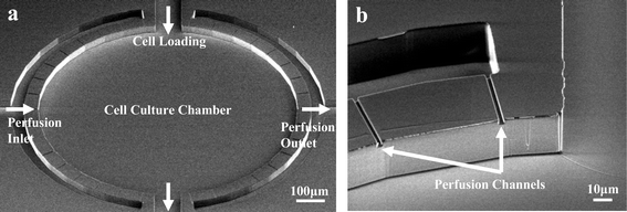 | ||
| Fig. 2 High aspect ratio design. (a) SEM picture of a single unit of the arrayed device before bonding. Multiple perfusion channels surround the main culture chamber. The microchamber is 40 µm in height with a diameter of 1 mm. Each culture unit has four fluidic access paths. (b) SEM image of perfusion channel dimensions. Each perfusion channel had a width of 2 µm and height of 2 µm. | ||
The microfluidic cell culture array was fabricated by using soft-lithography technology and replicate molding (Fig. 3). SU-8 negative photoresist (Microchem Corportion) was used as the master template. First, the SU-8 2002 was patterned on a silicon wafer to define the 2 µm high perfusion channels. A 40 µm SU-8 2050 layer was then spin coated on top of the perfusion channels. Because the SU-8 2050 is substantially thicker than SU-8 2002, the surface was planarized after spin coating. The cell culture chamber and other channels were then photolithographically defined. PDMS (Sylgard 184, Dow Corning Corporation) was prepared with a 10 : 1 ratio between the base and the curing agents. The PDMS was then poured on the 2-level SU8 mold. The mold was degassed in a vacuum chamber for 10 min before curing in a 70 °C oven for 4 h. The device dyes were then cut by a razor blade and the fluidic connection ports were punched using an 18 gauge flat tip needle. The device was then irreversibly bonded to a coverglass (Fisher Scientific) after oxygen plasma treatment (PlasmaTherm Etcher, 50 W, 2 Torr, 40 s) on both the bottom of the device and the glass slide. 20 gauge stainless steel connectors (Instech Laboratories) and soft tubings (Cole Parmer Corporation) were used to provide fluidic connections to a syringe pump (Cole Parmer 74900).
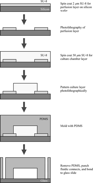 | ||
| Fig. 3 Flow diagram of fabrication process. | ||
C. Simulation and characterization
The high aspect ratio of the microfluidic design creates a large fluidic resistance in the perfusion channels. This has the effect of providing a uniform flow profile at the outlet of each perfusion channel. To support this claim that the high aspect ratio design would help create a uniform culture microenvironment, we developed a finite element model for simulation of steady state velocity profile and time-dependent mass transfer characteristics of the device. The finite element model was built using the FEMLAB™ software package (version 3.0, Comsol, Stockholm, Sweden) on a PC platform.First, the Navier–Stokes equations were solved for the carrier liquid to obtain the flow field. This field was then fixed and the time-dependent simulation of the convection–diffusion equation was performed. The dimensions of the domains are equal to the values chosen in the preceding section. The 2D domain also contains a longer part for the perfusion channels to accommodate the fluidic resistance in 3D. The entire domain was meshed using four-noded tetrahedron finite elements and a time step of 0.5 s was used in all species transport simulations. The solutions were found to be practically independent of the spatial and temporal discretization with the grids and time step used. This was assessed for the 2D simulations by coarsening and refining the grid spacing and the time steps by a factor of two and repeating the calculation.
As the boundary condition, a fully developed velocity profile was imposed at the inlet with maximum velocity corresponding to the inlet flow rate (0.2 µL min−1). Zero traction and no slip boundary conditions were set at the outlet and on the walls, respectively. The flow profiles under various flow rates were simulated. Due to the large fluidic resistance of the perfusion channels compared to the microchamber, most of the fluidic pressure drops on these narrow channels, helping the fluid flow inside the microchamber to be uniform (Fig. 4). This analysis indicates that the fluid velocity varies less than 5% of the inlet flow rate over 90% of the culture area.
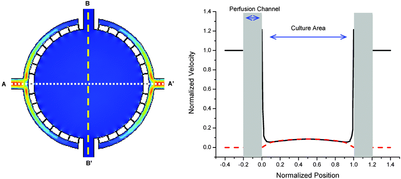 | ||
| Fig. 4 Finite element simulation of fluid velocity inside the chamber. Cross sections are plotted along the axis of perfusion (A–A′ solid line) and the perpendicular axis (B–B′ dashed line). Due to the high aspect ratio between the perfusion channels and the cell culture chamber, the velocity profile inside the microchamber is uniform within 5% of the inlet velocity over 90% of the culture area. | ||
For the mass transfer simulation, the carrier liquid is modeled as glucose solution at 293 K with a solute diffusion coefficient D = 1 × 10⁻¹⁰ m2 s−1. In the nutrient transport simulation, a constant concentration of nutrient (C = 25 mM L−1) in the carrier liquid is supposed on inlet. The medium turn around rate is 8 min−1 under 0.2 µL min−1 flow rate and the mass transfer was verified with food dye at different time points (Fig. 5).
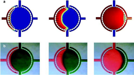 | ||
| Fig. 5 Mass transfer. (a) Simulation of fluid flow through the microfluidic cell culture chamber. Medium is introduced from the perfusion inlet at 0.2 µL min−1. The entire chamber is evenly filled, suggesting mass transfer can be assumed uniform for cells at different locations in the chamber. Images depicted after 2, 5, and 15 s of flow. (b) Flow of colored dye at the corresponding time points verifies the mass transfer simulation. | ||
D. Results
Demonstration of cell culture in the device was performed using the human HeLa cell line. Proper sizes of elastic tubings were used to interface the microfluidic device with the syringe pump for fluidic control. The device and the tubings were sterilized under UV light before use. The device was initially prepared by filling with PBS to remove dead volume and bubbles inside the device. HeLa cell suspension was obtained at a concentration of 106 cells mL−1 and introduced into the microfluidic device via the top port. The cells were allowed to settle to the bottom of the chamber for 2 h at 37 °C. After confirming that cells were attached to the bottom of the chamber, CO2 independent medium (Gibco, NY) was continuously flowed through the perfusion channels using a syringe pump. During the continuous perfusion of the medium, the device was placed inside an incubator for humidity and temperature control (37 °C). Since the PDMS was gas permeable,9 O2 diffusion from the air was sufficient for cell culture. Due to the continuous flow of fresh medium into the culture chambers, a CO2 buffering system for pH was not necessary for cell survival. Cell growth was monitored daily using a phase-contrast microscope. At a medium flow rate of 0.13 µL min−1, the cells were able to grow to confluency after 8 days (Fig. 6). Cell viability inside the microchamber was checked by flowing calcein AM (2 µM) from the loading port to label living cells, indicating a viability of over 95%.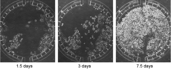 | ||
| Fig. 6 Cell growth inside the microfluidic cell culture array. Mammalian HeLa cells (human cell line derived from cervical cancer) were used to characterize growth inside microfluidic chambers. Cells were loaded from the top channel on day 0. Buffered culture medium supplemented with serum was continuously supplied from the perfusion inlet. Cell growth was recorded daily. At day 7.5, cells were grown nearly to confluency. | ||
E. Discussion
The ability to control the cell culture environment on the microscale offers many opportunities for improving biomedical and biotechnological research. The first generation of microfabricated cell culture devices focused on patterned surfaces and simple microchannels. In order to enhance control over the culture environment, we utilized a two-level lithography process. This solved the issue of non-uniform mass transfer in microfluidic channels caused by the parabolic laminar flow profile. The high aspect ratio design for the microfluidic device offers many advantages for cell culture, including size exclusion of cells, promoting a uniform fluidic environment, ability to generate arrays of chambers, ease of fabrication, and manipulation of reagents without an extensive valve network. We hope to further develop this technology in order to provide a complete miniaturized cell culture system for high throughput cell-based assays.We envision such a platform to have applications in many different disciplines. More cost efficient drug screening tools10 and rapid bioreactor optimization11 could benefit the pharmaceutical industry. A portable cell culture array could be deployed in the field or clinic for point-of-care diagnostics of infectious agents or use in personal medicine. For example, clinical cell culture is used for the detection and identification of viruses, such as the causative agent of severe acute respiratory syndrome (SARS).12 Doctors can also derive important information about individual patients from cultured biopsies, such as for optimization of chemotherapy regimens.13 The ability to perform inexpensive high throughput experiments could also have a big impact on biological research, where thorough characterizations of experimental conditions are currently limited. For example, integration with microfluidic gradient generators14 enables providing a different culture condition in each chamber of an array. Using this concept, we have fabricated a PDMS cell culture device that can potentially assay 100 different conditions on a single chip. Initial characterization of a ten channel splitter indicated that the flow was uniform within each column, and a different reagent concentration could be introduced to different elements of the array (Fig. 1b). There was no cross flow between columns due to the high fluidic resistance imposed by the perfusion channels. Individually addressing each column and row could be attained through the implementation of a microfluidic valve network.15 By improving the efficiency of fluidic delivery, it is possible to introduce a level of quantitative control to experiments that are traditionally qualitative. There is also great promise in adapting microfluidic cell culture for research in tissue engineering.16
In this paper, we show the advantages of the high aspect ratio design between the culture chamber and perfusion channels and demonstrated the capability of culturing human tissue culture cells in an arrayed PDMS microdevice. Ongoing research is being conducted to fully miniaturize the system into a portable assay device. This might be accomplished through the integration of electro-osmotic pumps,17 optical sensors,18 and microphysiometers.19 The microfluidic cell culture array can impact on a wide range of applications in high throughput cell-based screening, bioinformatics, synthetic biology, quantitative cell biology, and systems biology in the near future.
References
- S. A. Sundberg, Curr. Opin. Biotechnol., 2000, 11, 47 CrossRef CAS.
- W. G. Lachnita, U. Warrior, S. Gopalakrishnan, M. E. Schurdale and D. J. Burns, Drug Discov. Today, 2001, 6, 1200 CrossRef.
- T. H. Park and M. L. Shuler, Biotechnol. Prog., 2003, 19, 243 CrossRef CAS.
- G. M. Walker, H. C. Zeringue and D. J. Beebe, Lab Chip, 2004, 4, 91 RSC.
- E. Leclerc, Y. Sakai and T. Fujii, Biotechnol. Prog., 2004, 20, 750 CrossRef CAS.
- M. J. Powers, K. Domansky, M. R. Kaazempur-Mofrad, A. Kalezi, A. Capitano, A. Upadhyaya, P. Kurzawski, K. E. Wack, D. B. Stolz, R. Kamm and L. G. Griffith, Biotechnol. Bioeng., 2002, 78, 257 CrossRef CAS.
- K. Viravaidya and M. L. Shuler, Biotechnol. Prog., 2004, 20, 590 CrossRef CAS.
- G. Walker, M. Ozers and D. Beebe, Biomed. Microdev., 2002, 4, 161 Search PubMed.
- S. Charati and S. Stern, Macromolecules, 1998, 31, 5529 CrossRef CAS.
- J. Khandurina and A. Guttman, Curr. Opin. Chem. Biol., 2002, 6, 359 CrossRef CAS.
- Y. Kostov, P. Harms, L. Randers-Eichhorn and G. Rao, Biotechnol. Bioeng., 2001, 72, 346 CrossRef CAS.
- C. Drosten, S. Gunther, W. Preiser, S. van der Werf, H. R. Brodt, S. Becker, H. Rabenau, M. Panning, L. Kolesnikova, R. A. Fouchier, A. Berger, A. M. Burguiere, J. Cinatl, M. Eickmann, N. Escriou, K. Grywna, S. Kramme, J. C. Manuguerra, S. Muller, V. Rickerts, M. Sturmer, S. Vieth, H. D. Klenk, A. D. Osterhaus, H. Schmitz and H. W. Doerr, N. Engl. J. Med., 2003, 348, 1967 CrossRef CAS.
- W. T. Bellamy, Drugs, 1992, 44, 690 Search PubMed.
- N. Li Jeon, H. Baskaran, S. K. Dertinger, G. M. Whitesides, L. Van der Water and M. Toner, Nat. Biotechnol., 2002, 20, 826 CAS.
- T. Thorsen, S. J. Maerkl and S. R. Quake, Science, 2002, 298, 580 CrossRef CAS.
- H. Andersson and A. van den Berg, Lab Chip, 2004, 4, 98 RSC.
- S. Attiya, A. B. Jemere, T. Tang, G. Fitzpatrick, K. Seiler, N. Chiem and D. J. Harrison, Electrophoresis, 2001, 22, 318 CrossRef CAS.
- R. Ulber, J. G. Frerichs and S. Beutel, Anal. Bioanal. Chem., 2003, 376, 342 CAS.
- F. Hafner, Biosens. Bioelectron., 2000, 15, 149 CrossRef CAS.
Footnote |
| † These authors contributed equally to this work. |
| This journal is © The Royal Society of Chemistry 2005 |