Simulation of an oxygen membrane-based combined cycle power plant: part-load operation with operational and material constraints
Received
22nd May 2009
, Accepted 10th September 2009
First published on 4th November 2009
Abstract
This paper presents the design and part-load performance of a natural gas-fired oxy-combustion combined cycle power plant for CO2 capture. The combustion chamber of a conventional gas turbine was replaced by a membrane reactor, making it possible to obtain a highly concentrated CO2 stream for long-term storage. The focus was on power plant operation with a view to operational and material constraints of individual process components to ensure their proper performance and required lifetime. In this respect, the mixed-conducting membrane modules were of particular interest. Temperature as well as concentration limitations for CO2 and other chemical species narrowed the operating window. Other critical reactor components added further constraints. For part-load operation of the power plant, two load control strategies were analysed for the gas turbine operating at constant rotational speed. In the first load control strategy, variable guide vanes were used to manipulate the mass flow of air to the gas turbine compressor. This degree of freedom was used to control the turbine exit temperature. In the second control strategy, variable guide vanes were not used and the turbine exit temperature was allowed to vary. For both load control strategies, the mean solid-wall temperature of the membrane modules was maintained close to its design value, which led to improved stability. The load-control strategy using variable guide vanes was superior to the strategy without variable guide vanes due to higher combined cycle efficiencies and increased load-reduction capability. Moreover, the performance of the catalytic combustors in the membrane reactor, operating at near stoichiometric conditions, also improved as a result of increased oxygen concentrations at part-load operation. Relevant process components were based on spatially distributed conservation balances for energy, species, mass, and momentum. A stability diagram was incorporated into the membrane module model to investigate the risk of degradation. Performance maps were used for turbomachinery components.
Broader context
At present, fossil fuels (oil, gas, and coal) represent the largest share of all primary energy sources and will most likely remain dominant over the coming decades. The combustion of fossil fuels produces large amounts of CO2 during the energy conversion process. With a share of over 60%, power generation represents the largest source of anthropogenic CO2. Carbon dioxide capture and storage is one option in the portfolio of mitigation methods to stabilize emissions of CO2. Oxy-combustion power plants using membrane technology have been proposed as one possible approach for CO2 capture. However, the use of membranes for integrated air separation is very challenging due to several constraints that limit power plant performance and the lifetime of critical process components.
|
1. Introduction
The power and industry sectors combined contribute more than 60% of all anthropogenic CO2 emissions.1 The increasing demand for energy will lead to further emissions increases unless environmental issues are addressed. CO2 capture and storage is one option in the portfolio of actions for stabilizing atmospheric greenhouse gases. Novel power plants with CO2 capture, along with system improvements of existing power plants, offer potential for controlling emissions. These novel power plants can be largely classified into oxy-combustion, pre-combustion, and post-combustion power plants.1 The principle of an oxy-combustion power plant concept is given in Fig. 1, and a detailed process flow sheet is shown in Fig. 2. In this oxy-combustion system, the combustor in a conventional gas turbine (GT) power plant (Fig. 3) is replaced by a membrane reactor, which is comprised of mixed-conducting membranes for integrated air separation.1–6 Dilution of the CO2 with nitrogen in the air coming from the GT compressor is avoided and only oxygen-depleted air is emitted to the atmosphere after it passes the heat recovery steam generator. However, the use of afterburners (Fig. 2) leads to some CO2 emissions, although efficiency and power output are both increased. Heat is generated by the combustion of natural gas, here assumed to be pure methane, with the oxygen that is transported through the membranes. The combustion products (mainly water vapour and CO2) are recycled to moderate the combustion temperature and to increase the driving force for oxygen transport. The recycle loop is indicated in Fig. 1 and Fig. 2. A fraction of this stream is bled off from the recycle loop and used to produce steam in a steam cycle for additional power generation. After heat recovery, the CO2 is conditioned, compressed, and transported to a storage site.
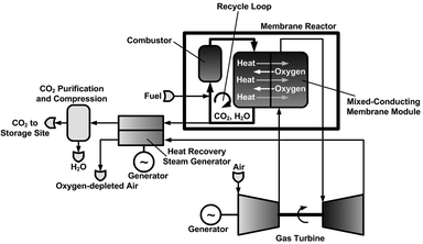 |
| | Fig. 1 Membrane-based combined cycle power plant. The temperature distribution is indicated throughout the process. | |
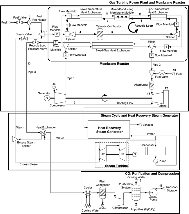 |
| | Fig. 2 Membrane-based combined cycle power plant with CO2 conditioning. | |
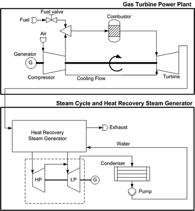 |
| | Fig. 3 Conventional combined cycle power plant. | |
The industrial use of such membranes for power generation is demanding with respect to properties that determine oxygen permeation and long-term stability of the materials used. Some general target properties are given in Table 1. In addition to desired oxygen transport properties, the membrane must maintain sufficient stability under all foreseeable operation conditions to prevent bulk decomposition and membrane failure caused by thermo-mechanical and chemical stresses. So far, there is no membrane material that has optimal properties for all potential operating conditions as well as for processing and cost-related aspects. For example, any increase in stability-related properties is usually associated with worsening of other properties, such as the oxygen permeation rate.7 Optimization of operating conditions of the membrane reactor should thus account for the material-specific properties of the membrane, including possible microstructural and surface degradation. Most of the highly permeable perovskite-related compositions containing alkaline-earth elements are partly or fully unstable under the operation conditions considered in this work because of interaction with gas species such as CO2 and water vapour.8,9 However, perovskite-related compositions without alkaline-earth cations give relatively low oxygen permeation fluxes.7,10,11 In this work, the dense membrane layer was assumed to be made of the perovskite-related material La2NiO4+δ![[thin space (1/6-em)]](https://www.rsc.org/images/entities/char_2009.gif) 12,13 and coated onto a porous support substrate. Using the same material for the porous support ensures thermo-mechanical and chemical integrity.14 Although this family of materials does not have the highest oxygen permeation rate, it has the major advantages of relatively low thermal and chemical expansion, the absence of alkaline-earth constituents, and relatively easy processing.13,15 The membrane modules and heat exchangers (HXs) in the membrane reactor are assumed to be counter-current two-fluid monoliths with a high area-to-volume ratio for high heat and mass transport,9,16 as shown in Fig. 4. A drawback of this monolith technology is the complex manifold system9 and a low tolerance of pressure differences, which lead to mechanical stress. Furthermore, Selimovic17 recently indicated that two-fluid monoliths exhibit a large pressure drop due to the flow distributors.
12,13 and coated onto a porous support substrate. Using the same material for the porous support ensures thermo-mechanical and chemical integrity.14 Although this family of materials does not have the highest oxygen permeation rate, it has the major advantages of relatively low thermal and chemical expansion, the absence of alkaline-earth constituents, and relatively easy processing.13,15 The membrane modules and heat exchangers (HXs) in the membrane reactor are assumed to be counter-current two-fluid monoliths with a high area-to-volume ratio for high heat and mass transport,9,16 as shown in Fig. 4. A drawback of this monolith technology is the complex manifold system9 and a low tolerance of pressure differences, which lead to mechanical stress. Furthermore, Selimovic17 recently indicated that two-fluid monoliths exhibit a large pressure drop due to the flow distributors.
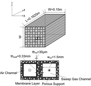 |
| | Fig. 4 Oxygen membrane module: two-fluid monolith (top), modelling manifold (bottom). | |
Table 1 Target properties of oxygen mixed-conducting membranes for power generation applications
| Relative oxygen nonstoichiometry variations with respect to the values under operation conditions |
Chemical stresses |
Δδ/δoperation < 20% |
| Creep rate |
Mechanical stresses |
<10−8 cm s−1![[thin space (1/6-em)]](https://www.rsc.org/images/entities/char_2009.gif) 75 75 |
| Oxygen ionic conductivity |
Oxygen permeation |
>0.1 S cm−1 |
| Electronic conductivity |
Oxygen permeation |
>10–30 S cm−1 |
| Thermal expansion coefficient |
Thermo-mechanical stresses |
8–20 ppm K−1![[thin space (1/6-em)]](https://www.rsc.org/images/entities/char_2009.gif) 75 75 |
Although a large number of membrane materials and configurations have been evaluated to date (see ref. 10, 11, 18–20, and references therein), there are only a few studies in the published literature that address incorporating membranes for air separation in power plants. Kvamsdal et al.21 analysed a membrane-based power plant using steady-state simulation tools, where process components were represented by lumped models. Such models provide information about efficiency and power output as well as average heat and mass transport rates. But a more realistic picture of performance, i.e. where operational and material constraints are incorporated into the analysis, cannot be given. Selimovic22 developed a two-dimensional model of the membrane module and analysed the membrane reactor using a zero-dimensional model. Further, Selimovic et al.23 developed a one-dimensional membrane module model based on a finite volume method. But the very important link between the membrane reactor and turbomachinery has yet to be evaluated.
The membrane-based power plant shares several similarities with solid oxide fuel cell GT hybrid cycles. For instance, both operate over similar temperature ranges.9,24 However, solid oxide fuel cell-based hybrid cycles have mostly been analysed for use in small-scale power plants with less than a few MW of power output. The variable rotational speed of the turbomachinery can thus be applied to load control, providing an additional degree of freedom in the system. The GT is here assumed to be connected to the electrical grid, which means that a variable shaft speed is not practical.
In the present work, a membrane-based combined cycle power plant (CCPP) was analysed with respect to design as well as part-load operation. Operational and material constraints were emphasized to maintain sound power plant performance where a reasonable lifetime of critical process components could be achieved, such as for the membrane modules. The membrane-based power plant was further compared to a conventional CCPP without CO2 capture to demonstrate the effect of CO2 capture on efficiency and power output.
2. Combined cycle power plant
In the detailed flow sheet of the membrane-based power plant (Fig. 2), fuel is injected into the membrane reactor by subsonic ejectors (Fig. 5). Ejectors provide compression without moving parts, which results in lower stress and high system reliability. Moreover, they feature a simple design, high temperature resistance, and low-cost fabrication and operation.25–28 Steam that is taken from the steam cycle must be added to maintain proper ejector performance. Fuel pre-heating is required to avoid two-phase flow in the ejectors. Compressed air is split after the GT compressor, where the majority is passed through the branch comprising low-temperature HXs, membrane modules, and high-temperature HXs. The remainder is led to the bleed-gas HXs. These two streams are mixed afterwards and fed to the afterburners. In addition to oxygen separation, the membrane modules operate as HXs. Oxygen is transported from the air to the sweep gas stream, whereas heat transport occurs in the opposite direction. In the catalytic combustors, the fuel reacts with highly diluted oxygen. Excess oxygen is required for stable and complete combustion.29,30 Afterburners increase the turbine inlet temperature to the thermal limit of the turbomachinery, thus increasing efficiency and power output. The CO2 produced in the afterburners is emitted to the atmosphere. It is not practical to capture these rather small amounts of CO2 due to their high nitrogen dilution. The exhaust gas is then fed into the heat recovery steam generator for further power generation, and also for producing steam that is used in the ejectors. After passing the bleed-gas HXs, the sweep gas enters the CO2-compression system including HXs for the cooling of the CO2-rich gas, flash condenser, compressor, purification system, and pump. In the purification system, impurities such as oxygen are removed to produce a highly concentrated stream of CO2. The gas separation can be accomplished by distillation.31–33 Carbon dioxide purities of more than 99% can be achieved by these processes.32 However, if the CO2 is used for enhanced oil recovery, the specifications may be more stringent.31,32 In this work it is assumed that all impurities, i.e. water and oxygen, are removed prior to end compression.
 |
| | Fig. 5 Section of the constant-area ejector model. | |
3. Gas turbine process component modelling
3.1 Monolithic membrane modules and heat exchangers
Oxygen permeation of the mixed-conducting membrane is controlled by both bulk diffusion and surface kinetics.12 Bulk diffusion was based on an approximate of the Wagner equation20| |  | (1) |
with c0 the concentration and D0 the self-diffusion coefficient of oxygen, thml the membrane thickness, n represents an additional fitting parameter used for pressure dependency, and pO2 the oxygen pressure. Please note that c0, D0, and n are temperature-dependent parameters. Fitting parameters were used to modify eqn (1) as well as the source term in the species conservation balances to make allowance for surface kinetic contributions. The energy conservation balance for the gas phase is given by34| |  | (2) |
and for the solid-wall (dense membrane layer and porous support)34| |  | (3) |
where the following Nusselt number correlation was used35| |  | (4) |
Species conservation in the gas phase for oxygen reads34| |  | (5) |
The pressure drop was based on36| |  | (6) |
with the friction factor35| | f![[thin space (1/6-em)]](https://www.rsc.org/images/entities/i_char_2009.gif) Re = 56.91 Re = 56.91 | (7) |
where ρ represents the density, cp is the heat capacity, T the temperature, v the fluid velocity, z the spatially distributed variable in axial direction, λ the thermal conductivity, α the area-to-volume ratio of the monoliths, hf the heat transfer coefficient, hO2 the enthalpy of oxygen in the gas phase, wch the channel width, L the monolith length, ΔP the pressure drop, and Re the Reynolds number. The index ‘g’ denotes the gas phase and ‘s’ the solid-wall.
The monolithic HXs in the membrane reactor were based on the same set of conservation balances. However, the source term for oxygen transport was omitted. Individual species conservation balances were replaced by a total mass balance to moderate model complexity.
3.2 Gas turbine
Isentropic efficiency calculations were applied for the basic GT compressor and turbine model.37 Steady-state performance maps were incorporated to calculate the mass flow, pressure ratio, isentropic efficiency, and cooling flow rate during off-design operation.38,39 Variable guide vanes (VGVs) were used to control the mass flow of air entering the GT compressor.37,39 The surge margin (SM) was calculated by39| |  | (8) |
Off-design performance of the GT turbine was represented by the Stodola equation40| | 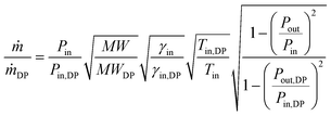 | (9) |
where ṁ is the mass flow, MW the molecular weight, and γ the isentropic exponent. The indexes ‘in’, ‘out’, and ‘DP’ indicate the inlet, outlet, and design point conditions, respectively.
3.3 Ejector
The one-dimensional ejector model was divided into five sections: (i) nozzle critical section, (ii) nozzle outlet, (iii) mixing section inlet, (iv) diffuser inlet/mixing section outlet, and (v) diffuser outlet. The description of ejector sections has been generalized here, where the indexes 1, 2, and 3 refer to inlet and outlet sections, respectively.
The energy balance was defined by36
| | | ṁ1(h1 + ½v21) + ṁ2(h2 + ½v22) = ṁ3(h3 + ½v23) + Hloss | (10) |
where
h is the enthalpy, and
Hloss is the heat loss. The mass balance is given by
36The momentum balance for the mixing section reads
36| | | P3A3 − P2A2 − P1A1 = ṁ1v1 + ṁ2v2 − ṁ3v3 | (12) |
where
A is the area.
3.4 Pipe
The pipe models account for further pressure drops in the power plant using the following friction factor35| | f![[thin space (1/6-em)]](https://www.rsc.org/images/entities/i_char_2009.gif) Re = 64 Re = 64 | (13) |
in conjunction with eqn (6).
3.5 Combustor
The combustor model (catalytic combustors and afterburners) was based on the following equilibrium reaction| | | CH4 + 2O2 ⇌ 2H2O + CO2 | (14) |
3.6 Recycle loop
The pressure in the recycle loop on the sweep gas side was calculated by the ideal gas law36| |  | (15) |
with m as the total mass in the recycle loop, V the volume, and R the universal gas constant.
3.7 Combined cycle power plant
The efficiency of the CCPP was calculated by37| |  | (16) |
with Pgen as the generator power output, Pcons is the sum of work related to power plant internal consumers, ṅfuel the mole flow of fuel and LHVfuel its lower heating value.
Further modelling assumptions for the combined cycle power plant can be found in Table 2.
Table 2 Detailed assumptions for the membrane-based and conventional combined cycle power plant
| Fuel preparation and handling of power consumption |
| ■ Fuel is assumed to be pure methane, available at 4 MPa |
| ■ Fuel temperature in the membrane reactor after preheating is 398 K (fuel heating, e.g. by the CO2-rich exhaust gas prior to the CO2-compression system; additional heat integration was not included in the analysis) |
| ■ Fuel temperature to the afterburners 278 K |
| ■ Lower heating value = 8 MJ mol−1 |
| |
| Membrane reactor |
| ■ Number of manifolds of type 1 is 12 |
| ■ Number of manifolds of type 2 is 48 |
| ■ Membrane module length is 0.1625 m; high-temperature heat exchanger length is 0.355 m; low-temperature heat exchanger length is 0.9825 m; bleed-gas heat exchanger length is 1.5 m; the height and width of all monoliths is 0.15 m |
| ■ Gas channel width of membrane module and monolithic heat exchangers is 1.5 mm |
| ■ Thickness of the membrane layer is 30 μm |
| ■ Length of porous support with protective additives is 0.01625 m |
| ■ Area-to-volume ratio of the monoliths is 895 m2 m−3 |
| ■ Number of gas channels of the monoliths is 6690 |
| ■ Split fraction of air to the bleed-gas heat exchanger is 15% |
| ■ Radiative interaction between reactor components is neglected |
| |
| Gas turbine |
| ■ Variations of the isentropic efficiency for compressors are calculated by performance maps38 (84.5% in design) |
| ■ Variations of the isentropic efficiency for the turbine and the amount of cooling air that is extracted from the compressor discharge are calculated by performance maps39 (86.8% in design) |
| ■ Shaft mechanical efficiency is 99%76 |
| ■ Generator mechanical efficiency is 98.5%76 |
| ■ Cooling air fraction of compressed air is 11.6%39 |
| |
| Pipes |
| ■ Diameter of pipe 1 is 0.39 m; diameter of pipe 2 is 0.53 m; length of pipe 1 and pipe 2 is 5 m |
| ■ Diameter of pipe 3 is 0.2 m and length is 10 m |
| ■ Average velocity of pipe 1 is 53.7 m s−1; average velocity of pipe 2 is 56.1 m s−1; average velocity of pipe 3 is 21.1 m s−1 |
| |
| Ejector |
| ■ Heat loss = 1% |
| ■ Isentropic efficiency for the section-wise ejector model is based on data from ref. 77 and 78 |
| ■ Operation in the critical mode70–72 (the mass flow of steam is therefore set) |
| ■ Diffuser area = 0.058 m2; diffuser throat area = 9.86 cm2; nozzle area = 0.064 cm2 |
| ■ Velocity in the mixing section and diffuser outlet is 121 m s−1 and 2 m s−1, respectively |
| |
| Catalytic combustors and afterburners |
| ■ Heat loss = 1%76 |
| |
| Heat recovery steam generator and steam cycle |
| ■ Steam temperature delivered to the GT power plant is 573 K |
| ■ Pressure levels in steam cycle are 0.5 MPa and 8 MPa, respectively |
| ■ UA for steam-producing heat exchanger is 16 kW K−1 |
| ■ UA for cooler is 103.4 kW K−1 |
| |
| CO2 purification and compression process |
| ■ Variations of the isentropic efficiency for compressors are calculated by performance maps38 |
| ■ Flash condenser: phase equilibrium between vapour and liquid phase operating at constant pressure79 |
| ■ Purification system: total work input = 0.44 MJ per kg CO2;31,32 cooling water flow rate = 23.2 kg per kg CO2;32 complete removal of all impurities |
| ■ Pump isentropic efficiency = 75%80 |
| |
| Other assumptions |
| ■ Ambient air: T = 288 K; pressure = 0.1 MPa; composition: 79% nitrogen, 21% oxygen |
| ■ Cooling water: T = 283 K, temperature raise = 10 K, pressure = 0.1 MPa |
3.8 Model implementation
The models of the membrane-based GT power plant and conventional GT power plant as well as the CO2-compression system were executed in gPROMS.41 The HX for steam production and sweep gas cooling were modelled in Aspen HYSYS.42 For both simulation tools, a Soave–Redlich–Kwong equation of state was used with a very good match for the physical properties, meaning that consistency was maintained. The steam cycle and HRSG were modelled in GTPRO/GTMASTER.43 The steam pressures for the dual-pressure steam cycle were selected in accordance with current industry practice for this range of power output and this type of steam cycle.
4. Operational and material constraints for individual process components
The operational and material constraints for the membrane-based power plant are explained and summarized in Table 3. Constraints that also need to be considered in a conventional power plant are indicated by italic letters.
Table 3 Operation and material constraints for the membrane-based combined cycle power plant. Constraints for the conventional power plant are indicated by italic letters
| Process component |
Constraint |
Effect |
Limit |
| Catalytic combustors |
Minimum oxygen mole fraction |
Performance loss and failure due to unstable and incomplete combustion |
0.5 mol%30 |
| Catalyst in the catalytic combustors |
Maximum sulfur concentration |
Performance loss and failure due to sulfur poisoning |
ppb range64 |
| Catalyst in the catalytic combustors |
Maximum temperature gradients |
Performance loss and failure due to thermal shocks |
Depending on process conditions |
| Ejectors |
Thermodynamic conditions with respect to temperature, pressure, and composition |
Performance loss due to formation of vapour–liquid phase |
Depending on process conditions |
| Ejectors |
Minimum total pressure difference in mixing section |
Performance loss due to operation outside the critical mode |
025,81 |
| Ejectors |
Pressure of actuating (fuel and steam mixture) fluid |
Performance in critical range |
Depending on process conditions70 |
|
GT compressor
|
Maximum variable guide vane angle limit
|
Mass flow reduction by variable guide vanes
|
30%
73,74
|
|
GT compressor
|
Minimum surge margin
|
Performance loss and failure due to a sudden drop in pressure and detrimental aerodynamic pulsation
|
5%
66,67
|
|
GT turbine
|
Cooling air fraction to GT turbine
|
Performance loss and failure due to thermo-mechanical stresses
|
Depending on technology
39
|
|
GT turbine
|
Maximum turbine inlet temperature
|
Performance loss and failure due to thermo-mechanical stresses
|
1530 K
82
|
| High-temperature heat exchangers |
Maximum temperature |
Performance loss and failure due to thermo-mechanical stresses |
1573 K16 |
| Low-temperature heat exchangers |
Minimum temperature |
Performance loss and failure due to thermo-mechanical stresses |
673 K16 |
| Low-temperature heat exchangers |
Maximum sulfur concentration |
Performance loss and failure due to sulfur poisoning |
50 ppb16 |
| High-temperature heat exchangers |
Maximum sulfur concentration |
Performance loss and failure due to sulfur poisoning |
Depending on process conditions (poisoning is favoured at low temperatures) |
| Dense membrane layers and porous support |
Maximum sulfur concentration |
Performance loss and failure due to sulfur poisoning |
10 ppb16 |
| Dense membrane layers and porous support |
Minimum temperature |
Performance loss and failure due to thermo-mechanical stresses |
1173 K16 |
| Dense membrane layers and porous support |
Maximum temperature |
Performance loss and failure due to thermo-mechanical stresses and chemical interaction |
1323 K16 |
| Dense membrane layers and porous support |
Thermodynamic conditions with respect to membrane temperature, CO2 and O2 pressure in sweep gas |
Performance loss and failure due to carbonate formation |
Depending on process conditions9,16 |
| Dense membrane layers and porous support |
Thermodynamic conditions with respect to membrane temperature, CO2 and O2 pressure in sweep gas |
Performance loss and failure due to oxidation |
Depending on process conditions16 |
| Dense membrane layers and porous support |
Thermodynamic conditions with respect to membrane temperature, CO2 and O2 pressure in sweep gas |
Performance loss and failure due to hydroxide formation |
Depending on process conditions (favoured at low temperatures)9 |
| Membrane modules and monolithic heat exchangers |
Maximum total pressure difference |
Performance loss and failure due to mechanical stresses |
0.1 MPa |
|
Pipes
|
Maximum fluid velocity
|
Safety; performance loss and failure due to noise and vibrational problems
|
60 m s−1![[thin space (1/6-em)]](https://www.rsc.org/images/entities/char_2009.gif) 83 83 |
| All reactor components |
Maximum difference in thermal expansion coefficients |
Performance loss and failure due to thermo-mechanical stresses |
10–17% |
| Sealings and joined ceramics |
Maximum leakage rate |
Performance loss and failure due to leakage |
0.1% |
4.1 Mixed-conducting membranes
At isothermal conditions, the membrane expands with decreasing oxygen pressure. When decreasing the temperature at constant oxygen pressure, the membrane contracts because of thermal and chemical geometric changes as a result of a increased equilibrium oxygen stoichiometry.44 These volume changes must be considered to keep mismatches low between the porous support material and the dense membrane layer as well as between all connections of the membrane-reactor components. Membrane compositions such as La2NiO4+δ, and its derivatives offer some advantages because of their relatively low thermal and chemical expansion.13,15 But the relatively large concentration of La3+ cations may still reduce membrane performance. Hence, essentially isothermal conditions and the highest possible operating temperature must be maintained to minimize stresses.45,46 In theory, the thermo-mechanical stability of the membrane may be improved by applying additional constituents such as Ag or Pd,47 but the long-term performance of these kinds of membranes must still be carefully evaluated, because similar stability problems may arise with these materials. Membrane material decomposition may be associated with redox instability, interaction with gaseous species and/or kinetic demixing, resulting from a slow, but non-negligible cation transport under the oxygen chemical potential gradient.48–50 Chemically-induced expansion is among the most important thermo-mechanical properties that relate to the volume changes under the oxygen chemical potential gradients and determines the applicability of membrane materials. These volume changes lead to oxygen anion concentration gradients, variable-valence cation oxidation states and average cation size across the membranes. The resultant differential strains induce mechanical stresses that can lead to fracture. Similar effects can also arise from thermal expansion.
In general, when operating the membrane in a temperature range of 973–1073 K at high CO2 and water vapour pressures, the use of any membrane materials containing substantial amounts of alkaline-earth elements may be problematic, if carbonate formation or oxidation is thermodynamically favourable under the corresponding equilibrium conditions.51 Sundkvist et al.16 provided a tentative stability diagram for a membrane that shows regions where carbonate formation and oxidation are likely to occur. This stability diagram was extended by incorporating the oxygen pressure as an additional parameter, as shown in Fig. 6. Temperatures below 1173 K in conjunction with high CO2 pressures lead to the formation of oxycarbonates, primarily La2O2CO3,51 followed by the complete decomposition according to the general reactions
| |  | (17) |
or, more likely,
| |  | (18) |
Increasing the oxygen pressure leads to a moderately higher stability in CO
2 (non-vertical dashed line in
Fig. 6). A reduced oxygen pressure has an opposite and stronger effect (non-vertical dotted line in
Fig. 6).
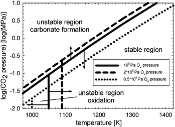 |
| | Fig. 6 Stability diagram for the dense membrane layer and porous support based on ref. 16. Stable and unstable operation regions are shown with respect to CO2 and oxygen pressure in the sweep gas as well as solid wall temperature. | |
At moderate operation temperatures, the La2NiO4+δ membrane may degrade due to oxidation.16,52 For undoped La2NiO4+δ, this process occurs via several reactions, leading to the separation of layered Ruddlesden–Popper compounds and lanthanum oxide.52 The latter may then react with CO2 or water vapour. At the final stage, the oxidative decomposition can be expressed as
| | | La2NiO4+δ + (½ − δ − γ)O2 ⇌ LaNiO3−γ + ½La2O3 | (19) |
The stability limit at low temperatures is shifted to the right (vertical dashed line in Fig. 6) and left (vertical dotted line in Fig. 6) when the oxygen chemical potential increases or decreases, respectively. However, both processes could promote carbonate formation. A more complex shape of the membrane stability boundary could therefore emerge.
The dense membrane layer is assumed to be on the air side because of the high risk of carbonate formation at the sweep gas inlet. The porous support acts as a protection layer by limiting diffusion of gaseous species such as CO2. Caro53 suggested adding small amounts of oxygen to improve stability. But this would reduce oxygen transport because of a lower driving force in addition to a more complex reactor design. Exposing the membrane on the feed side to high oxygen pressures increases the risk of oxidation. In this work the risk of carbonate formation was considered to be more serious than oxidation. Stabilizing components were assumed to be incorporated into the pores of the membrane support layer at a high risk of carbonate formation. These additives should be catalytically active to increase oxygen permeation.
All known membrane materials contain chemical elements that may evaporate under operational conditions, for instance during start-up and shut-down of the power plant.9 For Ni-containing materials, this degradation mechanism involves primarily nickel hydroxide volatilization.54 The resulting La-enrichment at the membrane surface may facilitate other degradation processes such as lanthanum carbonate and/or hydroxide formation. Under equilibrium conditions, the presence of metal hydroxides on the membrane surface is thermodynamically favourable only at low temperatures, far from the operation conditions considered in this work. Hydroxide formation was consequently not incorporated into the membrane module model.
Pressure differences of the two fluids in the membrane modules and HXs larger than one bar must be avoided to maintain mechanical stability. Minimizing the wall thickness leads to increased oxygen and heat transport rates. But improved mass and heat transport by using thinner walls comes at the expense of less operability and robustness as well as the requirement of more advanced control equipment for the membrane reactor. The total pressure in the recycle loop is measured at the outlet of the bleed-gas HXs, but other locations are also possible.
Industrial supplies of natural gas typically contain 1 ppm SO2,55 which is still too high for the mixed-conducting material assumed here. Deep desulfurization is required.
4.2 Ceramic heat exchanger monoliths and sealing
The monolithic HXs in the membrane reactor are fabricated of materials that are stable in atmospheres with high oxygen pressure and gaseous species such as H2O, CO2, and CO.56 However, the HXs in the membrane reactor add some further constraints with respect to temperature limits (Table 3). Sulfur limitations and pressure differences between the two fluids are similar to those specified for the membrane module. Additional issues relate to the sealing of membrane reactor components. The sealant should be hermetical and chemically and thermo-mechanically stable15,57,58 for the entire operating range. In addition, the sealant and joined ceramic materials, such as flow distributors, should have similar thermal expansion coefficients to avoid significant mismatches.11,15,16,58,59 The number of sealants that satisfy these requirements is limited and includes primarily SiO2-containing glass ceramics, phosphates and various composites. Sealant materials based on BaO–La2O3–SiO2–SrO have been proven to show a close match to La2NiO4+δ ceramics.15,58
4.3 Catalytic combustors
Due to the low excess oxygen concentrations in conjunction with the high dilution of CO2 and water vapour, standard combustion technology cannot be used in the combustors in the membrane reactor. Instead, a staged catalytic combustor has been developed, where catalytic partial oxidation of methane is followed by complete oxidation under lean conditions. A mixture of CO and H2 is produced by catalytic partial oxidation, which provides a hydrogen-stabilized combustion process in the second combustion stage.29,60,61 Supported Rh-based catalysts are suitable for the combustor due to their high activity, selectivity, resistance to carbon deposition, and sulfur resistance.62,63 Nevertheless, deep desulfurization is required to prevent poisoning of the catalyst.64 The mechanical integrity of the catalyst and its supports in the combustors should withstand possible thermal shocks that can occur during rapid load changes as well as during start-up and shut-down of the power plant.55 Excess oxygen is required to maintain stable and complete combustion.29,30 But high concentrations of oxygen in the sweep gas give rise to higher energy and cooling water requirements for the purification system.31–33 Moreover, degradation of process components located downstream of the membrane reactor may also occur.65 If thermodynamic conditions are such that the generation of carbon monoxide cannot be avoided, the high-temperature HXs and bleed-gas HXs could be coated with a catalytic layer, where the carbon monoxide and all other combustible compounds are converted before being fed to the membrane modules and HX, respectively.
4.4 Turbomachinery and further fluid components
The GT compressor must have a sufficient SM (Fig. 7). Surging is a complex, transient flow reversal that can cause severe damage to the compressor airfoils.37,39 Walsh and Fletcher suggested a SM for GT compressors in the power sector of 15–20%.39 This value has been relaxed to increase the part-load capability of the membrane-based power plant. But further reduction below 5% is not recommended because the GT may then be operated in a regime of subsonic stall and blade flutter.37,66,67 Material constraints for the GT arise as a result of creep, oxidation, and low-cycle fatigue.37,68 It should be noted that techniques for inlet air cooling and NOx reduction can also significantly affect the operating point of the GT.66 Due to the lack of available data, such phenomena were not incorporated into the GT model.
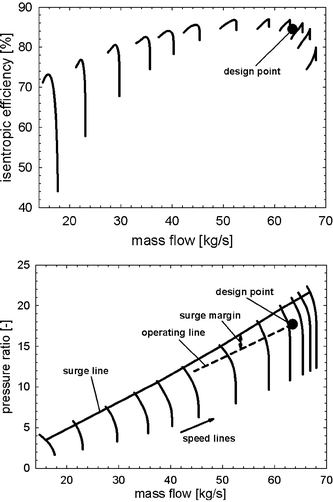 |
| | Fig. 7 Performance maps for the gas turbine compressor with respect to pressure ratio and isentropic efficiency.38 | |
The split ratio of air coming from the GT compressor is not controlled for reasons of control simplicity. Valves in the main streams should in general be avoided. After passing the two branches comprising (i) bleed-gas HXs and (ii) low-temperature HXs, membrane modules, and high-temperature HXs, both streams are mixed. The length of both paths is nearly equal. In practice, the total pressure drop could be different since the fluid that is passed through the bleed-gas HX branch meets fewer flow distributors. This could lead to oscillations in the membrane reactor. The split ratio of the combustor exhaust gas is indirectly controlled by means of the valve controlling the pressure in the recycle loop.
5. Part-load operation
In a conventional CCPP (Fig. 3), external power demand is controlled by varying the fuel flow rate to the combustors. This type of load-control method is not practical for the membrane-based power plant. Frequent and rapid changes of temperature in the membrane modules and other critical reactor components must be avoided to reduce stresses. For this reason, the mean solid-wall temperature of the membrane modules was chosen as a controlled variable. This variable is spatially distributed and cannot be directly measured. Inferential control69 can be used in order to establish a characteristic relationship between related variables, which are more easily accessible, and the mean-solid wall temperature. The fuel flow rate to the catalytic combustors is manipulated to keep the mean solid-wall temperature of the membrane modules close to the design value. Mechanical stresses in the membrane modules and monolithic HXs in the membrane reactor can be minimized by controlling the pressure difference between the two fluids. The pressure on the air side throughout the GT power plant is a result of thermodynamic property matching of the turbomachinery components and does not represent an available degree of freedom in the system. But the pressure in the recycle loop can be used to control the pressure difference. Furthermore, for proper ejector performance in the critical mode,70–72 the mass flow of steam must be adjusted. The power output is controlled by manipulating the mass flow of fuel to the afterburners. The set of controlled and manipulated variables is given in Table 4. The mass flow rate of air entering the GT compressor can be controlled by VGVs.39,73,74 This additional degree of freedom can be used to maintain a nearly constant turbine exit temperature, hence improving steam cycle performance. In modern GTs, however, the turbine exit temperature may still vary when VGVs are applied to optimize efficiency for the CCPP. In this paper, two load-control strategies are investigated: (i) where the turbine exit temperature is controlled using VGVs, and (ii) where VGVs are not used, which allows the turbine exit temperature to vary. In the following analysis, the load is reduced until one of the operational and material constraints in Table 3 is close to the limit (a safety margin was considered). It is worth mentioning that other load-control strategies proved insufficient. For instance, when seeking to keep the oxygen mole fraction in the catalytic combustors constant, no numerical solution could be obtained for the load-control strategy (i), thus indicating unfavourable thermodynamic conditions. For the load-control strategy (ii), rapid cooling of the membrane modules was observed so that degradation becomes more likely. Moreover, maintaining the combustion temperature at its design (maximum) value leads to part-load behaviour that is similar in terms of constraints to the two load-control strategies analysed in this paper, but calculation of the relative gain arrays69 showed that the assignment of the design case cannot be sustained, i.e. large variations at different frequencies and load points occurred. This load-control strategy would therefore be difficult to realize with standard control techniques. It should be noted that the use of afterburners gives substantial improvements for external power demands while operational and material constraints are not exceeded. Without afterburners, theoretically all the CO2 that is produced in the catalytic combustors could be captured. On the other hand, power plant performance and lifetime of critical reactor components would generally worsen.
Table 4 Set of controlled and manipulated variables
| Controlled variable set |
Manipulated variable set |
| Power output |
Fuel flow rate to the afterburners |
| Total pressure in recycle loop |
Recycle loop valve opening |
| Mean temperature of the membrane modules |
Fuel flow rate to the membrane-reactor |
| Ejector operational mode (critical) |
Steam valve opening |
| Turbine exit temperature |
Air mass flow to GT compressor by variable guide vanes |
6. Results and discussion
6.1 Design point performance
6.1.1 Membrane performance.
Fig. 8 shows the difference in CO2 pressure between the limit where carbonate formation can be avoided (the CO2 pressure difference is zero) and the sweep gas. At the sweep gas inlet of the membrane, the oxygen pressure reaches its minimum, whereas the pressure of CO2 is maximal, so that decomposition is favoured. The catalytically active components that are assumed to be incorporated into the parts of the porous support at risk result in considerable improvement with respect to stability. But these components also represent resistance to oxygen permeation. Both the oxygen pressure difference between the two fluids and the solid-wall temperature have a large impact on the oxygen flux, as can be seen from eqn (1).
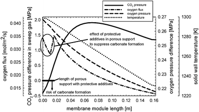 |
| | Fig. 8 Carbon dioxide pressure difference between the limit (zero) and that of the sweep gas, indicating the risk of carbonate formation for the dense membrane layer and porous support. The oxygen flux, oxygen pressure difference between the two fluids, and solid wall temperature in axial direction are also shown. | |
6.1.2 Combined cycle power plant.
Table 5 presents selected flow streams for the membrane-based GT power plant (Fig. 2). The process conditions for design operation have been adjusted to obtain a combustion temperature of 1473 K (stream 5), an excess oxygen mole fraction of approximately one percent in the catalytic combustors (stream 5), and a turbine inlet temperature of approximately 1530 K (stream 11). The GT turbine then requires 7.3 kg s−1 (approximately 12%) of the compressed air for cooling purposes (stream 2). Large quantities of cooling water are needed to further cool the CO2-rich gas from the membrane reactor before it enters the flash condenser (stream 14), and in the distillation column to further purify the CO2 stream (stream 15). In design operation, the membrane-based CCPP reaches an efficiency of 47.1% with a power output of 30.4 MW. In comparison, the efficiency of a conventional CCPP without CO2 capture (Fig. 3) is 53.3%, using the same GT specifications for mass flow rate of air into the GT compressor and turbine inlet temperature. The power output is 36.2 MW.
Table 5 Design case results for the membrane-based CCPP (Fig. 2)
| Stream No. |
T/K |
P/MPa |
ṁ/kg s−1 |
x
N2 [mol%] |
x
O2 [mol%] |
x
CH4 [mol%] |
x
H2O [mol%] |
x
CO2 [mol%] |
| 1 |
288 |
0.1 |
63.5 |
79 |
21 |
0 |
0 |
0 |
| 2 |
707 |
1.79 |
7.3 |
79 |
21 |
0 |
0 |
0 |
| 3 |
489 |
4 |
1.6 |
0 |
0 |
55.8 |
44.2 |
0 |
| 4 |
802 |
1.78 |
37.1 |
0 |
8.1 |
3.5 |
65.8 |
22.6 |
| 5 |
1473 |
1.76 |
37.1 |
0 |
1.1 |
0 |
72.8 |
26.1 |
| 6 |
1330 |
1.76 |
32.1 |
0 |
1.1 |
0 |
72.8 |
26.1 |
| 7 |
1258 |
1.76 |
35.5 |
0 |
8.7 |
0 |
67.2 |
24.1 |
| 8 |
1189 |
1.77 |
47.7 |
79 |
21 |
0 |
0 |
0 |
| 9 |
1258 |
1.76 |
44.7 |
83.7 |
16.3 |
0 |
0 |
0 |
| 10 |
278 |
1.75 |
0.3 |
0 |
0 |
100 |
0 |
0 |
| 11 |
1531 |
1.7 |
60.8 |
81.7 |
15.3 |
0 |
2 |
1 |
| 12 |
875 |
0.1 |
60.8 |
81.7 |
15.3 |
0 |
2 |
1 |
| 13 |
710 |
1.75 |
5 |
0 |
1.1 |
0 |
72.8 |
26.1 |
| 14 |
283 |
0.1 |
181.1 |
0 |
0 |
0 |
100 |
0 |
| 15 |
283 |
0.1 |
53.6 |
0 |
0 |
0 |
100 |
0 |
| 16 |
263 |
11 |
2.3 |
0 |
0 |
0 |
0 |
100 |
6.2 Part-load performance
6.2.1 Load-control strategy with variable guide vanes in the gas turbine compressor.
Fig. 9 shows the part-load performance maps for the membrane-based power plant with VGVs in the GT compressor for load control. Load reduction can be achieved until the limit of the VGVs (−30% from design point) is reached, i.e. down to approximately 63%. In part-load operation, less fuel is required for both the catalytic combustors and afterburners to maintain a nearly constant solid wall temperature of the membrane modules and turbine exit temperature. This is because of the reduced mass flow of air entering the membrane reactor. The mass flow of fuel to the afterburners is linked to the power output and consequently decreased when the load is reduced. The amount of steam that is required to maintain ejector performance during the critical regime is decreased when the power output is reduced. The decreasing SM of the GT compressor, which is caused by matching the thermodynamic properties of the membrane reactor and the turbomachinery, is shown in Fig. 7. Matching between the membrane reactor and turbomachinery makes it necessary to reduce the pressure in the recycle loop so that the average pressure differences between the two fluids in the membrane modules and monolithic HXs are minimized. The amount of steam needed to obtain proper ejector performance decreases for lower power outputs. It should be noted that the ejector operates not far from the specified limit (Table 3) for low power outputs (Fig. 10). The pressure in the recycle loop depends on the mass in all process units comprising the recycle loop. A large decrease in the recycle loop pressure is therefore accompanied by higher average pressure differences between the two fluids for the membrane modules as well as monolithic HXs (Fig. 10). Higher oxygen concentrations in the catalytic combustors were obtained because of the lower mass in the recycle loop (Fig. 10). The membrane-based power plant demonstrates good performance in terms of efficiency. However, rather heavy losses in power output arise when compared to a conventional CCPP (Fig. 11).
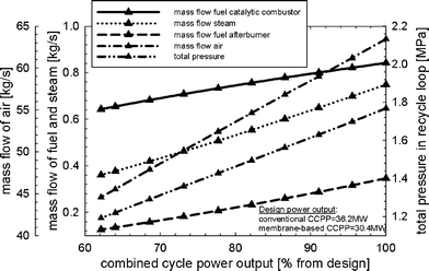 |
| | Fig. 9 Part-load performance maps with respect to mass flow of air to the gas turbine compressor, fuel to the catalytic combustors and afterburners, steam to the ejectors, and total pressure in the recycle loop for the load-control strategy with VGVs and controlled turbine exit temperature. | |
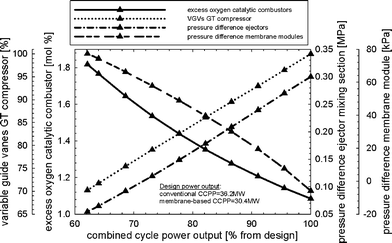 |
| | Fig. 10 Percentage of variable guide vane closure in the gas turbine compressor, excess oxygen in the catalytic combustors, pressure difference in the mixing section of the ejectors, and the average pressure difference across the membrane modules for the load-control strategy with VGVs and controlled turbine exit temperature. | |
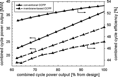 |
| | Fig. 11 Power output and efficiency of the membrane-based and conventional combined cycle power plant for the load-control strategy with VGVs and controlled turbine exit temperature. | |
6.2.2 Load-control strategy without variable guide vanes in the gas turbine compressor.
Fig. 12 shows the part-load performance maps for the membrane-based power plant for load control where VGVs in the GT compressor were not used. The load can be reduced until the limit of the oxygen concentration in the catalytic combustors (0.5 mol%) is reached, i.e. to approximately 82% of design. The mass flow of fuel to the afterburners decreases when the power output is reduced. The mass flow of fuel to the catalytic combustors must increase to maintain a nearly constant mean solid wall temperature of the membrane modules. The need for steam to maintain ejector operation in the critical mode is decreased during part-load operation (Fig. 12). There is only a slight decrease in the pressure ratio in the GT so that the pressure in the recycle loop can also remain close to its design value. Less compression work is hence required in the CO2-compression system and the SM of the GT compressor increases (Fig. 13). Maintaining a high pressure and mass in the recycle loop comes at the expense of substantially lower excess oxygen concentration in the catalytic combustors. The efficiency of CCPP is generally lower when compared to that of load-control strategy (i) since the steam cycle efficiency is sensible for changes in the turbine exit temperature (Fig. 14). As for the load-control strategy (i), heavy losses in power output arise compared to a conventional CCPP with equal design specifications for the turbomachinery.
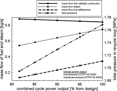 |
| | Fig. 12 Part-load performance maps with respect to mass flow of fuel to the catalytic combustors and afterburners, steam to the ejectors, and total pressure in the recycle loop for the load-control strategy without VGVs and uncontrolled turbine exit temperature. | |
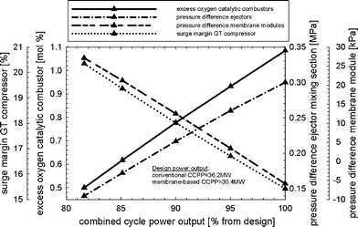 |
| | Fig. 13 Excess oxygen in the catalytic combustors, surge margin of the gas turbine compressor, pressure difference in the mixing section of the ejectors, and the average pressure difference across the membrane modules for the load-control strategy without VGVs and uncontrolled turbine exit temperature. | |
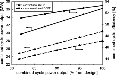 |
| | Fig. 14 Power output and efficiency of the membrane-based and conventional combined cycle power plant for the load-control strategy without VGVs and uncontrolled turbine exit temperature. | |
6.3 CO2 emissions
For both load-control strategies, the CO2 capture rate increases when power output is reduced because of the reduced mass flow of fuel to the afterburners (Fig. 15).
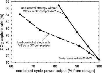 |
| | Fig. 15 Carbon dioxide capture rate of the membrane-based combined cycle power plant for the two load-control strategies. | |
7. Conclusions
Based on detailed modelling of individual process components, a membrane-based combined cycle power plant (CCPP) was analysed in design as well as part-load operation. The mixed conducting membrane has a narrow operation window in terms of thermodynamic properties, impurities and mechanical load. Careful control of process conditions and use of additional technological measures can improve stability of the membrane modules and other critical process components. Operation of the membrane modules at elevated and essentially isothermal conditions results in reduced thermo-mechanical and chemical stresses. The mean solid wall temperature of the membrane modules was therefore chosen as a controlled variable in the power plant, which can be manipulated by the mass flow of fuel to the catalytic combustors in the membrane reactor. At a constant rotational speed of the gas turbine (GT), basically two load-control strategies can be applied, i.e. first with and second without the use of variable guide vanes (VGVs) in the GT compressor to manipulate the mass flow of air. For the load-control strategy with VGVs, this additional degree of freedom can be used to control the turbine exit temperature. In the second load-control strategy without VGVs, the turbine exit temperature is allowed to vary. The former load-control strategy is superior due to improved combined cycle efficiencies and a larger part-load operation window. For this load-control strategy the angle of VGVs is limiting with a relatively wide range for part-load operation, i.e. the load can be reduced to approximately 62%. The performance of the catalytic combustors in a membrane reactor operating at nearly stoichiometric conditions improves during part-load operation because of higher oxygen mole fractions. For the load-control strategy without VGVs, the catalytic combustors are the constraining process components. The limit of the excess oxygen mole fraction (0.5 mol%) is reached at approximately 82% power output.
The use of mixed-conducting membranes for integrated air separation in this oxy-combustion power plant is very challenging due to several operational and material constraints that need to be considered, the reduced part-load operation capability of the GT power plant, and the need for further highly critical process components, such as catalytic combustors. But if technical challenges can be solved that are mainly associated with the mixed-conducting membrane itself, this membrane-based power plant has the potential to contribute to reduce CO2 emissions in the power generation sector.
Symbols and abbreviations
Notation
|
A/m2 | Area |
|
c
0/mol m−3 | Oxygen concentration |
|
c
p/J mol−1 K−1 or J kg−1 K−1 | Heat capacity at constant pressure |
|
D
0/m2 s−1 | Self-diffusion coefficient for oxygen |
|
f
| Friction factor |
|
h/J mol−1 | Specific enthalpy |
|
h
f/J s−1 m−2 K−1 | Heat transfer coefficient |
|
H
loss/J s−1 | Heat loss |
|
J
O2/mol m−2 s−1 | Oxygen flux |
|
k
| Constant |
|
L/m | Monolith length |
|
LHV
fuel/J mol−1 | Lower heating value |
|
m/kg | Mass |
|
ṁ/kg s−1 | Mass flow rate |
|
MW/kg mol−1 | Molecular weight |
|
n
| Fitting parameter |
|
Nu
| Nusselt number |
|
P/Pa, J s−1 | Pressure, power output |
|
p
O2
| Oxygen pressure |
|
R/J mol−1 K−1 | Universal gas constant |
|
Re
| Reynolds number |
| SMc | Surge margin |
|
T/K | Temperature |
|
th/m | Thickness |
|
U/W m−2 K−1 | Overall heat transfer coefficient |
|
v/m s−1 | Fluid velocity |
|
w
ch/m | Gas channel width of monolith |
|
z/m | Spatially distributed variable in axial direction |
Greek letters
|
α/m2 m−3 | Area-to-volume ratio of the monoliths |
|
γ
| Heat capacity ratio |
|
λ/J s−1 m−1 K−1 | Thermal conductivity |
|
η
| Efficiency |
|
Π
| Pressure ratio |
|
ρ/kg m−3 | Density |
Subscripts
| i | Sweep gas,air |
| cons | Consumer |
| DP | Design point |
| g | Gas phase |
| gen | Generator |
| ml | Membrane layer |
| s | Solid phase |
Abbreviations
| CCPP | Combined cycle power plant |
| GT | Gas turbine |
| HX | Heat exchanger |
| SM | Surge margin |
| VGV | Variable guide vane |
Acknowledgements
This publication forms a part of the BIGCO2 project, which is being conducted under the strategic Norwegian research program called Climit. The authors acknowledge their partners: StatoilHydro, GE Global Research, Statkraft, Aker Clean Carbon, Shell, TOTAL, ConocoPhillips, ALSTOM, the Research Council of Norway (178004/I30 and 176059/I30), Gassnova (182070) and FCT, Portugal (PTDC/CTM/64357/2006) for their support.
Knut Ingvar Åsen, Jens Bragdø Smith and John Arild Svendsen (StatoilHydro, Norway) are gratefully acknowledged for discussions on several aspects of the gas turbine power plant.
The reviewers are acknowledged for their valuable comments on the paper.
References
-
IPCC Special Report; Carbon Dioxide Capture and Storage; Summary for Policymakers, ed. B. Metz, O. Davidson, H. de Coninck, M. Loos and L. Meyer, Cambridge University Press, UK, 2005, p. 431, http://www.ipcc.ch/publications_and_data/publications_and_data_reports_carbon_dioxide.htm Search PubMed.
-
U. L Linder, E. Eriksen and K. Asen, Method of operating a combustion plant and a combustion plant, US Pat. 20040011048, 2004 Search PubMed.
-
T. Bruun and S. Hamrin, Combustion installation, WO Pat. 2007/060209A1, 2007 Search PubMed.
-
T. P. Bruun, L. Gronstad, K. Kristiansen, B. Werswick and U. Linder, Device for combustion of a carbon containing fuel in a nitrogen free atmosphere and a method for operating said device, WO Pat. 02/053969 A1, US Pat. 20050053878, 2005) Search PubMed.
- T. Griffin, S. G. A. Sundkvist, K. and T. Bruun, Advanced zero emissions gas turbine power plant, J. Eng. Gas Turbines Power, 2005, 127(1), 81–85 CrossRef CAS.
-
A. C. Bose, Inorganic Membranes for Energy and Fuel Applications, Wiley-VCH Verlag GmbH & Co., Weinheim, Germany, 2009 Search PubMed.
- V. V. Kharton, A. A. Yaremchenko, A. V. Kovalevsky, A. P. Viskup, E. N. Naumovich and P. F. Kerko, Perovskite-type oxides for high-temperature oxygen separation membranes, J. Membr. Sci., 1999, 163(2), 307–317 CrossRef CAS.
-
M. F. A. Carolan, P. N. Dyer, J. M. Labar Sr. and R. M. Thorogood, Process for recovering oxygen from gaseous mixtures containing water or carbon dioxide which process employs ion transport membranes, US Pat. 5261932, 1993) Search PubMed.
-
E. Drioli and L. Giorno, Membrane operations: innovative separations and transformations, Wiley-VCH, Weinheim, 2009 Search PubMed.
- Y. Liu, X. Tan and K. Li, Mixed conducting ceramics for catalytic membrane processing, Catal. Rev. Sci. Eng., 2006, 48(2), 145–198 CrossRef CAS.
- J. Sunarso, S. Baumann, J. M. Serra, W. A. Meulenberg, S. Liu, Y. S. Lin and J. C. Diniz da Costa, Mixed ionic-electronic conducting (MIEC) ceramic-based membranes for oxygen separation, J. Membr. Sci., 2008, 320(1–2), 13–41 CrossRef CAS.
- J. B. Smith and T. Norby, On the steady-state oxygen permeation through La2NiO4+ membranes, J. Electrochem. Soc., 2006, 153(2), A233–A238 CrossRef CAS.
-
B. E. Vigeland, R. Glenne, T. R. J. Breivik and S. Julsrud, Membrane and use thereof, WO Pat. 2001/023078. 2001 Search PubMed.
- A. V. Kovalevsky, V. V. Kharton, F. M. M. Snijkers, J. F. C. Cooymans, J. J. Luyten and F. M. B. Marques, Oxygen transport and stability of asymmetric SrFe(Al)O3-[]-SrAl2O4 composite membranes, J. Membr. Sci., 2007, 301(1–2), 238–244 CrossRef CAS.
-
O. Paulsen, Rigid bonded glass ceramic seals for high temperature membrane reactors and solid oxide fuel cells, PhD thesis, Norwegian University of Science and Technology, Trondheim, 2009 Search PubMed.
- S. G. Sundkvist, S. Julsrud, B. Vigeland, T. Naas, M. Budd, H. Leistner and D. Winkler, Development and testing of AZEP reactor components, Int. J. Greenhouse Gas Control, 2007, 1(2), 180–187 CrossRef CAS.
-
F. Selimovic, Computational analysis and modeling techniques for monolithic membrane reactors related to CO2 free power processes, thesis for Licentiate of Engineering, Lund University, Lund, 2007 Search PubMed.
- A. Leo, S. Liu and J. C. D. da Costa, Development of mixed conducting membranes for clean coal energy delivery, Int. J. Greenhouse Gas Control, 2009, 3(4), 357–367 CrossRef CAS.
- A. Thursfield and I. S. Metcalfe, The use of dense mixed ionic and electronic conducting membranes for chemical production, J. Mater. Chem., 2004, 14(16), 2475–2485 RSC.
-
P. J. Gellings, H. J. M. Bouwmeester, The CRC handbook of solid state electrochemistry, CRC Press, Boca Raton, Fla., 1997 Search PubMed.
- H. M. Kvamsdal, K. Jordal and O. Bolland, A quantitative comparison of gas turbine cycles with CO2
capture, Energy, 2007, 32(1), 10–24 CrossRef CAS.
-
F. Selimovic, Modelling of transport phenomena in monolithic structures related to CO2 free power processes, Lund University, doctoral thesis, Lund, 2005 Search PubMed.
-
F. Selimovic, J. Eborn, B. Sunden and H. Tummescheit, Dynamic analysis of an O2 separating membrane reactor for CO2-emission free power processes, American Society of Mechanical Engineers, Chicago, IL, United states, 2006 Search PubMed.
-
R. P. O'Hayre, Fuel cell fundamentals, Wiley, Hoboken, N.J, 2009 Search PubMed.
- F. Marsano, L. Magistri and A. F. Massardo, Ejector performance influence on a solid oxide fuel cell anodic recirculation system, J. Power Sources, 2004, 129(2), 216–228 CrossRef CAS.
- Y. Yi, A. D. Rao, J. Brouwer and G. S. Samuelsen, Fuel flexibility study of an integrated 25 kW SOFC reformer system, J. Power Sources, 2005, 144(1), 67–76 CrossRef CAS.
- M. L. Ferrari, D. Bernardi and A. F. Massardo, Design and testing of ejectors for high temperature fuel cell hybrid systems, J. Fuel Cell Sci. Technol., 2006, 3(3), 284–291 CrossRef CAS.
- C. Invernizzi and I. Paolo, Heat recovery from a micro-gas turbine by vapour jet refrigeration systems, Appl. Therm. Eng., 2005, 25(8–9), 1233–1246 CrossRef CAS.
-
T. Griffin, D. Winkler, M. Wolf, C. Appel and J. Mantzaras. Staged catalytic combustion method for the advanced zero emissions gas turbine power plant, American Society of Mechanical Engineers, Vienna, Austria, 2004, pp. 705–711 Search PubMed.
-
K. I. Åsen, Gas Processing and CO2, StatoilHydro ASA, Porsgrunn, Norway, personal communication, 2008.
- A. Aspelund and K. Jordal, Gas conditioning-The interface between CO2 capture and transport, Int. J. Greenhouse Gas Control, 2007, 1(3), 343–354 CrossRef CAS.
- G. Pipitone and O. Bolland, Power generation with CO2 capture: Technology for CO2 purification, Int. J. Greenhouse Gas Control, 2009, 3(5), 528–534 CrossRef CAS.
- H. Li, J. Yan and M. Anheden, Impurity impacts on the purification process in oxy-fuel combustion based CO2 capture and storage system, Appl. Energy, 2009, 86(2), 202–213 CrossRef CAS.
- K. Eichhorn Colombo, L. Imsland, O. Bolland and S. Hovland, Dynamic modelling of an oxygen mixed conducting membrane and model reduction for control, J. Membr. Sci., 2009, 336(1–2), 50–60 CrossRef CAS.
-
F. Kreith and M. S. Bohn, Principles of heat transfer, Brooks/Cole, Pacific Grove, Calif., 2001 Search PubMed.
-
R. B. Bird, W. E. Stewart, E. N. Lightfoot, Transport phenomena, Wiley, New York, 2006 Search PubMed.
-
H. I. H. Saravanamuttoo, G. F. C. Rogers, H. Cohen and P. V. Straznicky, Gas turbine theory, Prentice Hall, Harlow, 2009 Search PubMed.
-
J. Kurzke, Compressor and turbine maps for gas turbine performance computer programs - Component map collection, Dachau, Germany, 2004, http://www.gasturb.de/ Search PubMed.
-
P. P. Walsh, P. Fletcher, Gas turbine performance, Blackwell Science, Malden, Mass., 2004 Search PubMed.
-
W. Traupel, Thermische Turbomaschinen, Springer, Berlin, 1977 Search PubMed.
-
gPROMS Advanced Process Modelling software, Process Systems Enterprise Ltd (PSE), London, 2008, http://www.psenterprise.com Search PubMed.
-
Aspen HYSYS, Version 2006, Aspen Technology Inc., Cambridge, MA, 2006, http://www.aspentech.com Search PubMed.
-
Thermoflow, Thermoflow, Inc., Sudbury, MA, 2008, http://www.thermoflow.com/ Search PubMed.
-
M. F. A. Carolan, M. J. Watson, E. Minford, S. A. Motika and D. M. Taylor, Controlled heating and cooling of mixed conducting metal oxide materials, US Pat. 7122072, 2006 Search PubMed.
- E. Blond and N. Richet, Thermomechanical modelling of ion-conducting membrane for oxygen separation, J. Eur. Ceram. Soc., 2008, 28(4), 793–801 CrossRef CAS.
-
S. Hamrin, Control of
a gas turbine with hot-air reactor, US Pat. 20060230762, 2004 Search PubMed.
- V. V. Kharton, A. P. Viskup, A. V. Kovalevsky, E. N. Naumovich and F. M. B. Marques, Ionic transport in oxygen-hyperstoichiometric phases with K2NiF4-type structure, Solid State Ionics, 2001, 143(3–4), 337–353 CrossRef CAS.
- M. L. Fontaine, Y. Larring, T. Norby, T. Grande and R. Bredesen, Dense ceramic membranes based on ion conducting oxides, Ann. Chim. Sci. Mater., 2007, 32(2), 197–212 CrossRef CAS.
-
S. Stølen, T. Grande and N. L. Allan, Chemical thermodynamics of materials: macroscopic and microscopic aspects, Wiley, Chichester, 2004 Search PubMed.
- M. Martin, Materials in thermodynamic potential gradients, J. Chem. Thermodyn., 2003, 35(8), 1291–1308 CrossRef CAS.
- K. H. Foger, M. and T. W. Turney, Formation and thermal decomposition of rare earth carbonates, J. Mater. Sci., 1992, 27(1), 77–82 CrossRef CAS.
- D. O. Bannikov and V. A. Cherepanov, Thermodynamic properties of complex oxides in the La-Ni-O system, J. Solid State Chem., 2006, 179(8), 2721–2727 CrossRef CAS.
- J. Caro, Membranreaktoren für die katalytische Oxidation, Chem. Ing. Tech., 2006, 78(7), 899–912 CrossRef CAS.
-
B. E. B. Vigeland, Tor Protection of process equipment with significant vapor pressure by adding an evaporating component to gas in contact with said equipment, PCT Int. Appl., 2008 Search PubMed.
- R. Carroni, V. Schmidt and T. Griffin, Catalytic combustion for power generation, Catal. Today, 2002, 75(1–4), 287–295 CrossRef CAS.
-
S. V. Julsrud and B. Vigeland, A ceramic heat exchanger, WO Pat. 03/033986 A1, 2003 Search PubMed.
- K. S. Weil and B. J. Koeppel, Comparative finite element analysis of the stress-strain states in three different bonded solid oxide fuel cell seal designs, J. Power Sources, 2008, 180(1), 343–353 CrossRef CAS.
-
M. Budd, Barium lanthanum silicate glass-ceramics, US Pat. 7,189,668B2, 2007 Search PubMed.
-
M. Budd, Method of forming a glass ceramic material, US Pat. 6,475,938B1, 2002 Search PubMed.
- S. Eriksson, M. Boutonnet and S. Jaras, Catalytic combustion of methane in steam and carbon dioxide-diluted reaction mixtures, Appl. Catal., A, 2006, 312, 95–101 CrossRef CAS.
- S. Eriksson, M. Wolf, A. Schneider, J. Mantzaras, F. Raimondi, M. Boutonnet and S. Jaras, Fuel-rich catalytic combustion of methane in zero emissions power generation processes, Catal. Today, 2006, 117(4), 447–453 CrossRef CAS.
- S. Eriksson, M. Nilsson, M. Boutonnet and S. Jaras, Partial oxidation of methane over rhodium catalysts for power generation applications, Catal. Today, 2005, 100(3–4), 447–451 CrossRef CAS.
- A. Shamsi, Partial oxidation of methane and the effect of sulfur on catalytic activity and selectivity, Catal. Today, 2009, 139(4), 268–273 CrossRef CAS.
- S. Cimino, R. Torbati, L. Lisi and G. Russo, Sulphur inhibition on the catalytic partial oxidation of methane over Rh-based monolith catalysts, Appl. Catal., A, 2009, 360(1), 43–49 CrossRef CAS.
- S. I. Plasynski, J. T. L., H. G. McIlvried and R. D. Srivastava, Progress and New Developments in Carbon Capture and Storage, Crit. Rev. Plant Sci., 2009, 28(3), 123–138 CrossRef CAS.
- I. Roumeliotis and K. Mathioudakis, Evaluation of water injection effect on compressor and engine performance and operability, Appl. Energy, 2009 DOI:10.1016/j.apenergy.2009.04.039.
- K. Brun, R. Kurz and H. R. Simmons, Aerodynamic instability and life-limiting effects of inlet and interstage water injection into gas turbines, J. Eng. Gas Turbines Power, 2006, 128(3), 617–625 CrossRef CAS.
- T. J. Carter, Common failures in gas turbine blades, Eng. Failure Anal., 2005, 12(2), 237–247 Search PubMed.
-
G. Stephanopoulos, Chemical process control:
an introduction to theory and practice, Prentice-Hall, Englewood Cliffs, N.J., 1984 Search PubMed.
- Z. Yinhai, C. Wenjian, W. Changyun and L. Yanzhong, Fuel ejector design and simulation model for anodic recirculation SOFC system, J. Power Sources, 2007, 173(1), 437–449 CrossRef.
- Y. Zhu, W. Cai, Y. Li and C. Wen, Anode gas recirculation behavior of a fuel ejector in hybrid solid oxide fuel cell systems: Performance evaluation in three operational modes, J. Power Sources, 2008, 185(2), 1122–1130 CrossRef CAS.
- Y. Zhu and Y. Li, New theoretical model for convergent nozzle ejector in the proton exchange membrane fuel cell system, J. Power Sources, 2009, 191(2), 510–519 CrossRef CAS.
- J. H. Kim, T. S. Kim, J. L. Sohn and S. T. Ro, Comparative analysis of off-design performance characteristics of single and two-shaft industrial gas turbines, J. Eng. Gas Turbines Power, 2003, 125(4), 954–960 CrossRef.
- T. S. Kim and S. H. Hwang, Part load performance analysis of recuperated gas turbines considering engine configuration and operation strategy, Energy, 2006, 31(2–3), 260–277 CrossRef.
-
A. F. M. Sammells, V. Michael. Nonporous Inorganic Membranes for Chemical Processing, Wiley-VCH, Weinheim, 2006 Search PubMed.
- R. Cai and C. Gou, A proposed scheme for coal fired combined cycle and its concise performance, Appl. Therm. Eng., 2007, 27(8–9), 1338–1344 CrossRef CAS.
- I. W. Eames, S. Aphornratana and H. Haider, Theoretical and experimental study of a small-scale steam jet refrigerator, Int. J. Refrig., 1995, 18(6), 378–386 CrossRef.
- B. J. Huang, J. M. Chang, C. P. Wang and V. A. Petrenko, 1-D analysis of ejector performance, Int. J. Refrig., 1999, 22(5), 354–364 CrossRef.
-
J. M. A. Smith, M. Michael and H. C. Van Ness, Introduction to chemical engineering thermodynamics, McGraw-Hill, Boston, 2005 Search PubMed.
- P. Chiesa, S. Consonni, T. Kreutz and R. Williams, Co-production of hydrogen, electricity and CO2 from coal with commercially ready technology. Part A: Performance and emissions, Int. J. Hydrogen Energy, 2005, 30(7), 747–767 CrossRef CAS.
-
C. Stiller, Design, operation and control modelling of SOFC/GT hybrid systems, doctoral thesis, Norwegian University of Science and Technology, Faculty of Engineering Science and Technology, Trondheim, 2006 Search PubMed.
- M. Rodrigues, A. Walter and A. Faaij, Performance evaluation of atmospheric biomass integrated gasifier combined cycle systems under different strategies for the use of low calorific gases, Energy Convers. Manage., 2007, 48(4), 1289–1301 CrossRef CAS.
-
http://www.standard.no/
.
|
| This journal is © The Royal Society of Chemistry 2009 |
Click here to see how this site uses Cookies. View our privacy policy here. 


![[thin space (1/6-em)]](https://www.rsc.org/images/entities/char_2009.gif) 12,13 and coated onto a porous support substrate. Using the same material for the porous support ensures thermo-mechanical and chemical integrity.14 Although this family of materials does not have the highest oxygen permeation rate, it has the major advantages of relatively low thermal and chemical expansion, the absence of alkaline-earth constituents, and relatively easy processing.13,15 The membrane modules and heat exchangers (HXs) in the membrane reactor are assumed to be counter-current two-fluid monoliths with a high area-to-volume ratio for high heat and mass transport,9,16 as shown in Fig. 4. A drawback of this monolith technology is the complex manifold system9 and a low tolerance of pressure differences, which lead to mechanical stress. Furthermore, Selimovic17 recently indicated that two-fluid monoliths exhibit a large pressure drop due to the flow distributors.
12,13 and coated onto a porous support substrate. Using the same material for the porous support ensures thermo-mechanical and chemical integrity.14 Although this family of materials does not have the highest oxygen permeation rate, it has the major advantages of relatively low thermal and chemical expansion, the absence of alkaline-earth constituents, and relatively easy processing.13,15 The membrane modules and heat exchangers (HXs) in the membrane reactor are assumed to be counter-current two-fluid monoliths with a high area-to-volume ratio for high heat and mass transport,9,16 as shown in Fig. 4. A drawback of this monolith technology is the complex manifold system9 and a low tolerance of pressure differences, which lead to mechanical stress. Furthermore, Selimovic17 recently indicated that two-fluid monoliths exhibit a large pressure drop due to the flow distributors.
![[thin space (1/6-em)]](https://www.rsc.org/images/entities/char_2009.gif) 75
75![[thin space (1/6-em)]](https://www.rsc.org/images/entities/char_2009.gif) 75
75


![[thin space (1/6-em)]](https://www.rsc.org/images/entities/i_char_2009.gif) Re = 56.91
Re = 56.91

![[thin space (1/6-em)]](https://www.rsc.org/images/entities/i_char_2009.gif) Re = 64
Re = 64

![[thin space (1/6-em)]](https://www.rsc.org/images/entities/char_2009.gif) 83
83


