Synthesis of perylene monoimide derivative and its use for quasi-solid-state dye-sensitized solar cells based on bare and modified nano-crystalline ZnO photoelectrodes
John A.
Mikroyannidis
*a,
Minas M.
Stylianakis
a,
P.
Suresh
b,
M. S.
Roy
c and
G. D.
Sharma
*bd
aChemical Technology Laboratory, Department of Chemistry, University of Patras, GR-26500, Patras, Greece. E-mail: mikroyan@chemistry.upatras.gr; Fax: +30 2610 997118; Tel: +30 2610 997115
bPhysics Department, Molecular Electronic and Optoelectronic Device Laboratory, JNV University, Jodhpur, Raj. 342005, India
cDefence Laboratory, Jodhpur, Raj. 342011, India
dJaipur Engineering College, Kukas, Jaipur, Raj., India. E-mail: sharmagd_in@yahoo.com; Fax: +91 291 2720856; Tel: +91 291 2720857
First published on 17th September 2009
Abstract
A novel perylene monoimide derivative, PCA, with a strongly electron-donating cyclohexylimide segment, bulky alkylphenoxy substituents at the 1,7-bay positions of the perylene core and an acid anhydride as the strong coupling group was synthesized and used as sensitizer for dye-sensitized solar cells (DSSCs). PCA was readily soluble in common organic solvents, decomposed above 390 °C and had glass transition temperature of 64 °C. The absorption curves had maximum at 505–512 nm, with thin film absorption onset at 643 nm corresponding to an optical band gap of 1.93 eV. We have fabricated the quasi-solid-state DSSCs with ZnO nano-crystalline films deposited from different values of pH. It is found that the power conversion efficiency (PCE) is high when the pH value of sol gel is about 9. The PCE of DSSC fabricated with the gold-coated ZnO photoanode is higher than that for bare ZnO photoanode. This enhancement is attributed to the formation of Schottky barrier at the Au/ZnO interface that blocks the electron transfer from ZnO to dye and electrolyte, increasing the electron density in the conduction band of ZnO. The incorporation of TiO2 nanoparticles in polymer gel electrolyte further increases the PCE of DSSC up to 3.0%. The enhancement is primarily explained by studying the dark reaction, diffusion coefficient of tri-iodide and exchange current density in the interface of electrolyte/Pt counter electrolyte, and lifetime of electrons in the anode film.
Broader contextThe conversion of solar energy into electricity using dye sensitized solar cells (DSSCs) represents a most promising method for future large scale production, because of its low cost and high efficiency about 10–11%, at present. In the DSSCs, all components used in the fabrication, play important role in the optimization of its photovoltaic response. We describe the fabrication of quasi-solid-state DSSC based on a perylene monoimide derivative as sensitizer, Au nanoparticle-modified ZnO photoelectrode and polymer gel electrolyte with TiO2 particles. We have achieved power conversion efficiency about 3.0%, which is quite respectable for the DSSCs with polymer gel electrolyte and a low cost photosensitizer. |
Introduction
Energy demands and environmental pollution resulting in global warming have led to an intense search all over the world for alternative renewable energy sources, over the past decades. Since the first report in 1991 by Grätzel and coworkers,1 dye sensitized solar cells (DSSCs) based on wide band gap nano-crystalline TiO2 semiconductors loaded with dyes have attracted significant attention as low cost alternatives to conventional inorganic solar cells.2–6 At present, DSSCs based on large variety of Ru-complex photo-sensitizers have been explored and power conversion efficiency (PCE) about 9–12% have been reported.7–11 However, in view of their high cost, environmental problems, and difficult routes of synthesis, metal free organic photo-sensitizers are strongly desired. Pure organic dyes, compared with metal complexes, have higher absorption coefficients, which could save the amount of dyes used and reduce the thickness of the semiconductor film. Moreover, metal free organic dyes are easier to prepare and cost less compared with those of metal Ru based complexes. Metal free organic molecular photosensitizers such as squaraine, triphehylamine and xanthene organic dyes have been developed and show promising power conversion efficiencies. Recently, organic dye sensitized TiO2 solar cells have made great progress, and highest overall yield of solar cells sensitized by pure organic dyes has exceeded 6.3%.12 So organic dyes are promising and are expected to be a new type of sensitizer for DSSCs.12Perylenediimides (PDIs) represent one of the most widely studied classes of organic semiconductors with possible applications in photovoltaic cells, electrophotography, laser dyes and organic light-emitting diodes.13 They are inexpensive and easily accessible, attractive materials owing to intense, high fluorescence quantum yield and general photostability but suffer from poor solubility in common organic solvents. Synthesis of highly soluble PDIs is very important for the preparation of their thin films to be used in photoelectronic applications.14–16 They exhibit singlet energy transfer over unusually long distances. Most organic conducting materials can be described as p-type semiconductors; in contrast, PDIs are described as n-type semiconductors in which the major charge carriers are in their conduction band. Such materials are employed as electron accepting materials in all organic photovoltaic solar cells. Additionally, macroscopic oxide films are under intensive investigation due to their use in optoelectronic applications such as DSSCs, electrochromic and electroluminescent displays.
Recently, two near infrared absorbing perylene dyes containing benzo[e]indole have been used for DSSCs.17 Perylene monoimide dyes have been also used for DSSCs with overall conversion efficiency of 1.61%18 and 2.6%.19 Soluble perylene derivative has been used to enhance the photoelectric efficiency of the hybrid poly(3-hexylthiophene)/ZnO bulk-heterojunction solar cells.20 Finally, two soluble perylene–anthracene and perylene–pyrene compounds21 have been synthesized in our laboratory and used for quasi-solid-state DSSCs with PCE up to 3.42%.
Many investigators have made great efforts to enhance the performance of the DSSCs by improving the constituent's properties. These efforts are largely classified into four categories of developments: sensitizers,22–25 anodic materials,26–29 electrolytes30–32 and modification of anodic materials33–35 especially TiO2. Due to chemical stability and moderate charge capability of the TiO2, it has been most frequently used as a photoanode material in DSSCs. However, the electrons injected into the TiO2 layer are sometimes able to return to the sensitizer or the electrolyte due to electron recombination phenomena, causing a reduction in PCE.
Zinc oxide (ZnO) has attracted attention as a fascinating alternative to TiO2 in DSSCs because ZnO and TiO2 exhibit similar lowest conduction band edges and electron injection processes from excited dyes in DSSCs.36,37 Moreover, the lifetime of carriers in ZnO is significantly longer that that in TiO2.38 However, apart from some basic investigations, few studies have been made on high efficiency DSSCs incorporating ZnO, because their conversion efficiency of around 2–3% under 100 mW/cm2 illumination39–45 is much lower than that of DSSCs with TiO2. A serious problem for ZnO based DSSCs is the aggregation of dye which generates the Zn2+–dye aggregates. Such aggregates lower the electron injection efficiencies and filling of the nanopores of ZnO electrode, resulting in reduction in PCE of the DSSC. Therefore, novel processing of ZnO electrode is needed to overcome this problem and increase the PCE of the ZnO based DSSCs.
The present investigation describes the synthesis, characterization, the photophysics of a novel perylene monoimide, PCA, which was successfully used as sensitizer for DSSCs. PCA contains an electron-donating and solubilizing cyclohexyl ring which was connected with the perylene core via the imide nitrogen. Moreover, PCA carries bulky alkylphenoxy groups at the 1,7-bay positions of the perylene, the alkyl chains of which enhanced the solubility of the compound. Finally, PCA contains an acid anhydride as anchoring unit on the ZnO surface. The nature of the anchoring unit and the electron coupling between the perylene core and the ZnO surface would influence the cell performance. We have designed the quasi-solid-state DSSCs using PCA as sensitizer and ZnO nano-crystalline coated on fluorine doped tin oxide (FTO) glass substrate and polymer gel electrolyte. We found that the PCE of the device is highest when the photoelectrode with ZnO crystalline film deposited for ZnO sol gel having pH value about 9. The effect of gold nanoparticles deposited on the ZnO surface and incorporation of TiO2 particles into the polymer gel electrolyte has been discussed in detail.
Experimental
Characterization methods
IR spectra were recorded on a Perkin-Elmer 16PC FT-IR spectrometer with KBr pellets. 1H NMR (400 MHz) spectra were obtained using a Brucker spectrometer. Chemical shifts (δ values) are given in parts per million with tetramethylsilane as an internal standard. UV-vis spectra were recorded on a Beckman DU-640 spectrometer with spectrograde THF. TGA was performed on a DuPont 990 thermal analyzer system. Ground samples of about 10 mg each were examined by TGA and the weight loss comparisons were made between comparable specimens. Dynamic TGA measurements were made at a heating rate of 20 °C/min in atmospheres of N2 at a flow rate of 60 cm3/min. Thermomechanical analysis (TMA) was recorded on a DuPont 943 TMA using a loaded penetration probe at a scan rate of 20 °C/min in N2 with a flow rate of 60 cm3/min. The TMA experiments were conducted at least in duplicate to ensure the accuracy of the results. The TMA specimens were pellets of 10 mm diameter and ∼1 mm thickness prepared by pressing powder of sample for 3 min under 8 kp/cm2 at ambient temperature. The Tg is assigned by the first inflection point in the TMA curve and it was obtained from the onset temperature of this transition during the second heating. Elemental analyses were carried out with a Carlo Erba model EA1108 analyzer.Preparation of compounds
FT-IR (KBr, cm−1): 2954, 2900, 1803, 1764, 1592, 1506, 1364, 1230, 1176, 1014, 832.
1H NMR (CDCl3) ppm: 8.56–8.04 (m, 6H, perylene); 7.42 (m, 4H, phenylene meta to oxygen); 7.06 (m, 4H, phenylene ortho to oxygen); 1.40–1.50 (m, 16H, C(CH3)2CH2C(CH3)3); 1.22 (s, 18H, C(CH3)2CH2C(CH3)3).
Anal. Calcd. for C52H48O8: C, 77.98; H, 6.04. Found: C, 76.27; H, 5.86.
FT-IR (KBr, cm−1): 2950, 2865, 1800, 1766, 1654, 1592, 1504, 1364, 1216, 1176, 1014, 832.
1H NMR (CDCl3) ppm: 8.58–8.06 (m, 6H, perylene); 7.43 (m, 4H, phenylene meta to oxygen); 7.05 (m, 4H, phenylene ortho to oxygen); 2.57 (m, 1H, cyclohexyl proton close to the nitrogen); 2.04–1.84 (m, 26H, C(CH3)2CH2C(CH3)3 and other cyclohexyl protons); 1.24 (s, 18H, C(CH3)2CH2C(CH3)3.).
Anal. Calcd. for C58H59NO7: C, 78.97; H, 6.74; N, 1.59. Found: C, 77.21; H, 6.26; N, 1.40.
Synthesis of ZnO nanoparticles
The preparation of ZnO colloids or nanocrystals from decomposition or hydrolysis of zinc salts is an established route.47 We have adopted such an approach to prepare the ZnO nanocrystals from the hydrolysis as described below.The ZnO sol gel nano-crystalline power was prepared by dissolving zinc acetate dehydrate (CH3COO)2 Zn 2H2O) in methanol at room temperature. A clear solution of 0.5M was obtained by magnetic stirring at 30 °C for 2 h. The sol gel prepared was found stable and transparent. ZnO nano-crystalline powers were prepared by varying the pH value of solution from 5 to 11. The pH value of the solutions was adjusted to the desired value using sodium hydroxide (0.1N NaOH) solution. The modified solutions were again stirred for 1 h at room temperature. The clear solution was subsequently filtered through micron filter paper. The resulting transparent filtrate was kept for 3 h to complete the gelation and hydrolysis process. During this period of time, while ZnO precipitates were slowly crystallized and settled down in the bottom of the flask. The white precipitate was filtered and washed out with methanol to remove the staring materials and then dried at 120 °C for 2 h. The X-ray diffraction (XRD) of the samples was obtained using XRD diffractrometer. The crystallite size was determined by XRD peak broadening. The absorbance of the ZnO nanocrystalline power was measured using UV-visible spectrophotometer.
DSSCs were fabricated using the synthesized nano-crystalline ZnO powder. The nano-crystalline ZnO films were deposited on the fluorine doped tin oxide (FTO) glass substrates by the doctor blade technique. The substrates were cleaned using accetone, methanol and distilled water in sequence and then dried. The ZnO nano-crystalline powder ground by a mortar and pestle with methanol and prepared a paste. The paste was spread on the surface of FTO substrate with glass rod, using an adhesive tape as spacer. After drying in air, the films were sintered for 30 min at 350 °C in air.
To incorporate the gold (Au) nanoparticles on the surface of nano-crystalline ZnO films, the ZnO coated films were then immersed in a chloroauric acid (HAuCl4 1 mM) solution with a pH value between 8 and 9 being adjusted by sodium citrate (Na3C6H5O7 2H2O). The Au ions (Au3+) were reduced to neutral atoms attached to ZnO nano-crystalline surfaces.
Above electrodes were immersed in 5 × 10⁻⁴ M PCA solution in THF overnight at room temperature. The polymer gel quasi-solid-state electrolyte was prepared as follows. The appropriate amount of LiI (0.5 M)/(0.05 M I2), was dissolved in binary organic mixture of propylene carbonate (5 mL), poly(ethylene oxide) (PEO) (0.25 g) and 4-tert-butyl pyridine (TBP) (0.05 mL) in acetonitrile (5 mL) solvent. To incorporate the nano-filler in the polymer electrolyte different wt% TiO2 powder was added to it. The resulting mixture was heated at 60 °C under vigorous stirring until a viscous gel was formed, followed by cooling down to room temperature. After the sensitization, a quasi-solid-state polymer electrolyte spread on the top of PCA sensitized ZnO photoelectrode by the doctor blade technique. Pt coated FTO electrode was used as counter electrode. The DSSCs were made by clamping the photoanode consisting of polymer electrolyte and counter electrode.
The current voltage (J–V) characteristics in dark and under illumination intensity of 100 mW/cm2 were obtained with Keithley electrometer equipped with built in power supply. The intensity of the illumination was calibrated for AM 1.5 and measured using a lux meter. The incident photon to current efficiency of the devices was measured using a monochromator and the resulting current was measured employing Keithley electrometer under short circuit condition. The electrochemical impedance spectra of the DSSCs were carried out under illumination, by applying bias voltage equal to the open circuit voltage of DSSC, using Autolab Potentiostat-10 equipped with frequency response analyzer (FRA).
Results and discussion
Synthesis and characterization
Scheme 1 outlines the synthesis of compound PCA. Particularly, the bromination of 3,4,9,10-perylenetetracarboxylic dianhydride using bromine and a catalytic amount of iodine in sulfuric acid afforded compound 1.46 The 1,7-dibromo derivative was the predominant isomer which was obtained as reaction product.48 The latter reacted subsequently with 4-(1,1,3,3-tetramethylbutyl)-phenol in DMF in the presence of K2CO3 to yield the diether 2. Finally, 2 reacted with an equimolar amount of cyclohexamine in DMF in the presence of acetic acid to afford PCA. Compound PCA was soluble in THF, chloroform, dichloromethane and other common organic solvents due to the presence of the aliphatic segments.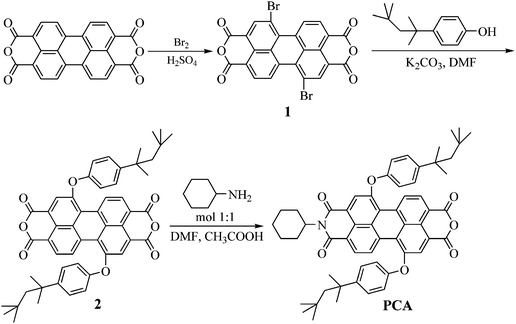 | ||
| Scheme 1 Synthesis of PCA | ||
The structure of PCA was confirmed by FT-IR and 1H NMR spectroscopy (see Experimental). The IR spectrum showed characteristic absorption bands at 2950, 2865 (C–H stretching of aliphatic segments); 1800, 1766 (anhydride); 1654 (carbonyl stretching); 1592, 1504 (aromatic breathing modes) and 1216, 1176 cm−1 (ether bond). The 1H NMR spectrum of PCA displayed an upfield multiplet at 8.58–8.06 ppm assigned to perylene protons. The phenylene protons meta and ortho to oxygen resonated at 7.43 and 7.07 ppm, respectively. Finally, the aliphatic moieties gave signals at the region of 2.57–1.24 ppm.
The thermal characterization of PCA was accomplished by TGA and TMA. The decomposition temperature (Td) and the char yield (Yc) at 800 °C, by TGA, as well as the glass transition temperature (Tg), by TMA, are listed in Table 1. Even though PCA contained a large fraction of aliphatic moieties, it exhibited a satisfactory thermal stability. Specifically, it had Td of 390 °C and Yc of 42%. The Tg was relatively low (64 °C) owing to the monomeric nature of the compound as well as the cyclohexylamine ring and the aliphatic side chains.
| a Decomposition temperature corresponding to 5% weight loss in N2 determined by TGA. b Char yield at 800 °C in N2 determined by TGA. c Glass transition temperature determined by TMA. d λa,max: The absorption maxima from the UV-vis spectra in THF solution or in thin film. e Egopt Optical band gap determined from the absorption onset in thin film. f Egel Electrochemical band gap determined from cyclic voltammetry. | |
|---|---|
| Tda (°C) | 390 |
| Ycb (%) | 42 |
| Tgc (°C) | 64 |
| λa,maxd in solution (nm) | 505 |
| λa,maxd in thin film (nm) | 512 |
| Egopte(eV) | 1.93 |
| HOMO (eV) | −5.9 |
| LUMO (eV) | −4.0 |
| Egelf(eV) | 1.90 |
Photophysical properties
The photophysical characteristics of PCA are summarized in Table 1. Fig. 1 depicts the normalized UV-vis absorption spectra of PCA in 10−5 M THF solution and thin film. The latter was prepared on quartz substrate from THF solution by spin-coating. The absorption curves had maximum (λa,max) around 500 nm, were broad and extended about up to 700 nm. Thus PCA had very nice absorption coverage over the visible and near infrared region which is desirable for photovoltaic applications. The thin film absorption onset was located at 643 nm corresponding to an optical band gap (Egopt) of 1.93 eV. This value of Egopt is comparable with that (2.05 eV) of two symmetrical compounds based on perylene–anthracene and perylene–pyrene, which have been used for quasi-solid-state DSSCs.21 Perylene polyimides containing p–n diblocks, which have been used for sensitization of TiO2 solar cells, showed band gap energies of 2.16–2.25 eV.49 Finally, polyether derivatives of perylenedimides adsorbed on monocrystalline metal oxide films exhibited Egopt of ∼2.20 eV.50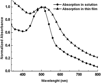 | ||
| Fig. 1 Normalized UV-vis absorption spectra of PCA in THF solution and thin film. | ||
Cyclic voltammetry (CV) measurements were performed on Autolab PGSTAT-30 electrochemical workstation equipped with three electrode system.The three electrode cell is composed of a gold working electrode, a platinum counter electrode and a SCE reference electrode calibrated against Fc/Fc+couple (+0.09V vs SCE). The CV characteristic of PCA was conducted in a distilled DMF containing 10−3 M of PCA and 0.5 M aqueous KCl as supporting electrolyte. The CV measurements were performed at a scan rate of 60 mV/s. The HOMO and LUMO energy levels are estimated from the onset oxidation potential and reduction potential observed in CV measurements and they are listed in Table 1.
Characterization of ZnO nano-crystalline films
We have recorded the XRD patterns of all ZnO samples obtained with different pH values. It is observed that the powders showed crystalline nature with peaks corresponding to (100), (002), (101) planes. The preferred orientation corresponding to the (101) plane is observed for ZnO powders. The spacing values and relative intensities of the peak coincide with the JCPDS card no. 36-1451 for ZnO powder. The crystallite size D was obtained by measurements of the broadening of diffraction lines and using Debye–Scherrer formula:where λ is the wavelength of CuKα irradiations (1.54 Å), β is the full width at half maximum of the peak corresponding to the plane (101) and θ is the angle obtained from 2θ value corresponding to maximum intensity peak in the XRD pattern. The diameter of crystallite size obtained ZnO nanoparticles varied from 8 to 16 nm. The largest size of a crystallite ZnO nanocrystal is about 16 nm, derived from the sol gel with pH value of 9. No sharp peak was observed for ZnO sol gel having pH value 6, which indicates the amorphous nature. The ZnO sol gel obtained at pH 9 has most intense peaks, which is thus most crystalline and has maximum crystallite size of 16 nm. The intensity of the reflected peak was found to decrease for the ZnO sol gel obtained at pH value greater than 9 and can be attributed to the higher reaction rate, when precipitate starts to dissolve.51
The growth of ZnO from the zinc acetate dihydrate as precursor using sol gel process generally undergo with four steps such as solvation, hydrolysis, polymerization and transformation into ZnO. The zinc acetate dehydrate precursor was first solvated in methanol, and then hydrolyzed, regarded as removal of the intercalated acetate ions and results in a colloidal gel of zinc hydroxide according to reaction (A). The size and activity of solvent influences the reactivity progress and final product. Methanol has small size and more active –OH and –OCH3 groups. Methanol can react more easily to form a polymer precursor with high polymerization degree, which is required to convert sol into gel.52 These zinc hydroxide splits into Zn2+ cation and OH− anion according to reaction (B) and followed by polymerization of hydroxyl complex to form Zn–O–Zn bridge and finally transformed into ZnO (reaction (C)).53
| Zn(CH3COO)2·2H2O + 2NaOH → Zn(OH)2 + 2CH3COONa + 2H2O | (A) |
| Zn(OH)2 + 2H2O → Zn(OH)42− + 2H+ | (B) |
| Zn(OH)42− ↔ ZnO + H2O + 2OH− | (C) |
We have observed that the growth of ZnO nanoparticles does not proceed, when the pH value of solution is below 6, because of the lack of Zn(OH)2 formation in the solution. Since pH value of solution controls the rate of ZnO formation, it affects the size and stability. The largest size was observed, when the pH of solution was about 9. Further increase in the pH value of sol gel leads to a decrease in the size of the crystallite nanoparticles. This may be attributed to the dissolution of ZnO (back reaction equation (C)). When ZnO reacts with OH−, the dissolution of ZnO occurs.
Photovoltaic properties of DSSCs
Fig. 2 shows the current–voltage characteristics of the DSSCs fabricated with ZnO nanocrystalline ZnO powder having different pH values, under illumination intensity of 100 mW/cm2. The photovoltaic parameters estimated from these curves are summarized in Table 2. It can be seen from the table that the open circuit voltage (Voc) is the same for all devices, whereas the short circuit current (Jsc), fill factor and PCE for the devices fabricated with ZnO nano-crystalline photoanode having pH 9 are higher than other devices. The better solar cell performance observed for this device may be attributed to the high quality nanocrystalline ZnO powder obtained from the solution having pH value of 9 and can be understood through the growth mechanism of nanocrystalline ZnO , as discussed above.| pH value of ZnO | Short circuit photocurrent (Jsc) (mA/cm2) | Open circuit voltage (Voc) (V) | Fill factor (FF) | Power conversion efficiency (η) (%) |
|---|---|---|---|---|
| 7 | 1.38 | 0.60 | 0.45 | 0.38 |
| 8 | 3.0 | 0.61 | 0.48 | 0.88 |
| 9 | 4.22 | 0.61 | 0.52 | 1.34 |
| 10 | 3.76 | 0.61 | 0.48 | 1.11 |
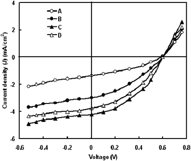 | ||
| Fig. 2 Current–voltage characteristics of DSCs using photoelectrode of ZnO synthesized at (A) pH 7 (B) pH 8 (C) pH 9 and (D) pH 10. | ||
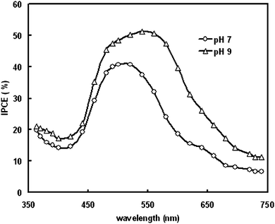
The incident photon to current efficiency of the DSSCs have been estimated using the following equation:
| IPCE(λ) = LHE(λ)ϕinηc |
Effect of gold nanoparticles layer deposited on the surface of nano-crystalline ZnO electrode
To further increase the photovoltaic performance of the DSSCs, we have used ZnO (pH = 9) photoanode coated with gold nanoparticles. Gold nanoparticles (NP) are one of the nano-systems in which light absorption in the visible region depends on the NP size due to the collective electron oscillations at the surface.54 Recently gold nanoparticles have been investigated for their photocatalytic,55 and potential photovoltaic applications.56 Tetsu et al., studied the enhancement of anodic photocurrent induced by visible light irradiation in a device structure based on gold nanoparticles.57The current–voltage characteristics under illumination intensity of 100 mW/cm2 are shown in Fig. 4. It was found that upon illumination, the device with ZnO surface coated with Au nanoparticles yields a Voc of 0.68 V and a Jsc of 5.2 mA/cm2 which are significantly higher than that for cell consisting of only bare ZnO photoanode. As a result the PCE was increased from 1.34% to 1.91%. The increase in the PCE can be understood by the following discussion.
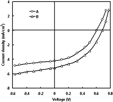 | ||
| Fig. 4 Current–voltage characteristics under illumination for DSSCs with (A) bare ZnO and (B) ZnO coated with Au nanoparticles. | ||
We assume that the electron transfer from the excited dye into ZnO nano-crystal surface occurs via a combination of two possible mechanisms. In the first mechanism the electrons from lowest unoccupied molecular orbital of dye are transported to the conduction band ZnO via tunneling effect across a thin layer of Au nanoparticles. The second mechanism involves two steps: First the FTO/ZnO/Au/dye electrode, upon excitation with visible light being predominantly absorbed by the dye, injects electrons into the gold nanoparticles as indicated in Fig. 5. We assumed that the injected electrons are accumulated in the gold nanoparticles, raising their Fermi levels towards more negative potentials until the matching with the Fermi level of ZnO leads to a quick transport of electrons from gold to ZnO.58 The electrons transferred to the ZnO surface are collected by FTO electrode, and thereby generate the photocurrent. Additionally, the Schottky barrier formed at the Au–ZnO interface reduces the charge recombination by blocking the transfer of electrons from ZnO to the dye and/or electrolyte thus improving the PCE of the DSSC. The generation of photocurrent in FTO/ZnO/Au/dye electrode in electrolyte can be illustrated as follows:
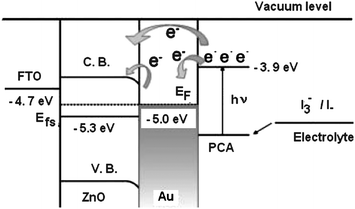 | ||
| Fig. 5 Energy level diagram and mechanism of photocurrent generation in the DSSC with FTO/ZnO/Au/PCA/polymer electrolyte. | ||
The improvement in the PCE can also be attributed to the suppression of charge recombination by the gold nanoparticle layer. The thin Au nanoparticle layer blocks the electron flow in the back direction (tri-iodides of redox electrolyte and cation of the dye), which contributes to the increase in the Voc.
Effect of nano-fillers in the polymer electrolyte
We have investigated the effect of TiO2 nano-fillers in the electrolyte on photovoltaic response of DSSC fabricated with Au coated ZnO (pH 9) photoelectrode. Fig. 6 demonstrates the dark current–voltage characteristics curves of DSSC as a function of nanoparticles concentration in electrolyte. The dark current results from the reduction of the tri-iodide by the conduction band electrons of the nano-crystalline wide band semiconductor used in the photoanode. The onset of the dark current of the DSSC with the various electrolytes occurs at 0.25, 0.28, 0.32 and 0.38 V for 0%, 2%, 6% and 8% wt, respectively. The onset of the dark current of DSSC with 8 wt% of NP occurs at the highest forward bias, which indicates that the 8 wt% NP can most efficiently suppress the dark reaction.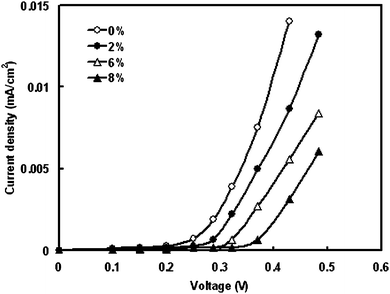 | ||
| Fig. 6 Effect of concentration of nano-filler in electrolyte on the dark current–voltage characteristics of DSSCs. | ||
Fig. 7 shows the J–V characteristics of the DSSC under illumination intensity of 100 mW/cm2 as a function of nanoparticle content in electrolyte. The photovoltaic characteristics are summarized in Table 3. It is found that the PCE (η) has been significantly enhanced by the composite electrolyte. With the increase of NP content to 8 wt%, the Jsc and Voc are both enhanced, reaching their maximum of 0.74 and 7.0 mA/cm2 and 0.74 V, respectively. As the content of NP increases above 8 wt%, both Voc and Jsc decrease.
| wt% of TiO2 | Short circuit photocurrent (Jsc) (mA/cm2) | Open circuit voltage (Voc) (V) | Fill factor (FF) | Power conversion efficiency (η) (%) |
|---|---|---|---|---|
| 0 | 5.2 | 0.68 | 0.54 | 1.91 |
| 5 | 5.7 | 0.70 | 0.55 | 2.2 |
| 8 | 7.0 | 0.74 | 0.58 | 3.0 |
| 10 | 6.35 | 0.70 | 0.55 | 2.44 |
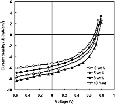 | ||
| Fig. 7 Current–voltage characteristics of the DSSCs with polymer electrolyte having different concentration of TiO2 nano-fillers. | ||
According to the electrochemical impedance spectroscopy (EIS) model of DSSC,59 the electron life time (τe) in the nano-crystalline thin film can be obtained from the characteristics angle frequency (ωmid) of the mid frequency (fmid) peak in the EIS bode phase plots, by the expression τe = 1/ωmid = 1/2πfmid.
We have measured bode phase plots for DSSCs with different concentrations of NP in electrolyte. It has been observed that the mid frequency peak in bode phase plots shifted towards the lower frequencies as the concentration of NP increased in the electrolyte. The bode phase plots of DSSC with 8% NP contents and without NP in electrolyte under illumination are shown in Fig. 8. The DSSC fabricated with composite electrolyte with 8 wt% of NP has minimum fmid 12 Hz as compared to without NP (fmid = 126 Hz), which corresponds to the maximum electron life time about 13 ms. The fmid of the DSSC with 8 wt% NP decreased by a factor of 10.5 as compared to the DSSC without NP, suggesting the τe is lengthened significantly.
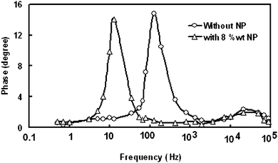 | ||
| Fig. 8 Bode plots of EIS spectra for DSSCs with (8 wt%) and without TiO2 nanoparticles in polymer electrolyte. | ||
To understand the influence of NP on the photovoltaic properties of DSSC, the electrochemical properties of the composite electrolyte were studied according to the thin layer cell model.60Fig. 9 shows the dependence of the diffusion coefficient of tri-iodide (DI3−) and exchange current density (Jo) on the NP content. DI3− is derived from the limiting current measurement60 by the expression
| DI3− = Jlimd/2nFCI3− |
| Jo = RT/nFRct |
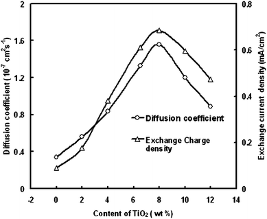 | ||
| Fig. 9 Dependence of diffusion coefficient of tri-iodide and exchange current density on TiO2 content. | ||
Fig. 9 shows that both the diffusion coefficient and Jo of the composite electrolyte with NP additive are significantly higher than that of pure ionic liquid electrolyte. When the content of NP is 8 wt %, diffusion coefficient and Jo are both up to maximum 1.56 · 10−7 cm2/s and 0.68 mA/cm2. The intercalation behavior of TBP molecule into NP can be responsible for the enhancement of Jo and diffusion coefficient. The enhancement of the Jo can be due to the increase of the active area of electrolyte/NP interface after the intercalation of TBP molecule into NP. The confinement effect by the nano-channels in the interlayer of NP may cause the enhancement of diffusion coefficient.
For a regenerative photoelectrochemical system, the Voc can be expressed as61
Under illumination, short circuit photocurrent of the DSSC can be given by equation Jsc = Jinj − Jr, where Jinj is the flux of injected electron and Jr is the I3− reduction current. The Jr can also be expressed as:
Conclusions
The perylene monoimide PCA was successfully synthesized by a three-step synthetic route. The cyclohexyl ring and the aliphatic chains enhanced the solubility of PCA. It showed satisfactory thermal stability and relatively low glass transition temperature. The absorption curves of PCA were broad with maximum around 500 nm and optical band gap of 1.93 eV. We have fabricated the quasi-solid-state DSSCs using ZnO anode deposited from the different values of pH sol. It was found that the highest PCE is for the DSSCs which were fabricated on ZnO nano-crystalline film having pH value of 8. Since the ZnO nanoparticles derived from the sol with pH 9 show highest crystallite size of 16 nm, as more dye has been adsorbed by them.The enhancement in photovoltaic performance of DSSC fabricated with gold coated ZnO photoanode is probably associated with injection of electrons from gold nanoparticles into ZnO and simultaneous tunneling of electrons from dye PCA to ZnO. We have also reported the effect of the addition of TiO2 nanoparticles in polymer gel electrolyte on the photovoltaic performance of DSSCs. The intercalation behavior of polymer gel with TiO2 NP can contribute to the enhancement of exchange charge density and diffusion coefficient of tri-iodide, which will depress the concentration of I3−. Furthermore, the polymer gel electrolyte with TiO2 can efficiently suppress the dark reaction. Hence, Jsc, Voc and corresponding PCE of DSSC are significantly enhanced. The increase in the electron lifetime also supports the increase in PCE.
References
- B. O'Regan and M. Grätzel, Nature, 1991, 353, 737 CrossRef CAS.
- M. Grätzel, Inorg. Chem., 2005, 44, 6841 CrossRef.
- M. Grätzel, J. Photochem. Photobiol., A, 2004, 164, 3 CrossRef CAS.
- T. A. Heimer, E. J. Heilweil, C. A. Bignozzi and G. J. Meyer, J. Phys. Chem. A, 2000, 104, 4256 CrossRef CAS.
- (a) M. K. Nazeeruddin, Coord. Chem. Rev., 2004, 248, 1161 CrossRef CAS; (b) P. V. Kamat, M. Haria and S. Hotchandani, J. Phys. Chem. B, 2004, 108, 5166 CrossRef CAS.
- N. A. Lewcenko, M. J. Byrnes, Y.-B. Cheng, S. M. Zakeeruddin, M. Grätzel and L. Spiccia, Chem. Commun., 2008, 3852 RSC.
- S. Ito, H. Miura, S. Uchida, M. Takata, K. Sumioka, P. Liska, P. Comte, P. Pechy and M. Grätzel, Chem. Commun., 2008, 5194 RSC.
- S. Hwang, J. H. Lee, C. Park, H. Lee, C. Kim, C. Park, M.-H. Lee, W. Lee, J. Park, K. Kim, N.-G. Park and C. Kim, Chem. Commun., 2007, 4887 RSC.
- C. S. Karthikeyan, H. Wietasch and M. Thelakkat, Adv. Mater., 2007, 19, 1091 CrossRef CAS.
- D. B. Kuang, C. Klein, S. Ito, J. E. Moser, R. Humphry-Baker, S. M. Zakeeruddin and M. Grätzel, Adv. Funct. Mater., 2007, 17, 154 CrossRef CAS.
- P. Wang, R. Humphry-Baker, J. E. Moser, S. M. Zakeeruddin and M. Grätzel, Chem. Mater., 2004, 16, 3246 CrossRef CAS.
- Q. H. Yao, L. Shan, F. Y. Li, D. D. Yin and C. H. Huang, New J. Chem., 2003, 27, 1277 RSC.
- F. Wuerthner, Pure Appl. Chem., 2006, 78, 2341 CrossRef.
- M. J. Ahrens, L. E. Sinks, B. Rybtchinski, V. Liu, B. A. Jones, J. M. Giaimo, A. V. Gusev, A. J. Goshe, D. M. Tiede and M. R. Wasielewski, J. Am. Chem. Soc., 2004, 126, 8284 CrossRef CAS.
- S. Mackinnon and M. Z. Y. Wang, J. Polym. Sci., Part A: Polym. Chem., 2000, 38, 3467 CrossRef CAS.
- H. Icil and S. Icli, J. Polym. Sci., Part A: Polym. Chem., 1997, 35, 2137 CrossRef CAS.
- Y. Jin, J. Hua, W. Wu, X. Ma and F. Meng, Synth. Met., 2008, 158, 64 CrossRef CAS.
- C. Zafer, M. Kus, G. Tukmen, H. Dincalps, S. Demic, B. Kuban, Y. Teoman and S. Icli, Sol. Energy Mater. Sol. Cells, 2007, 91, 427 CrossRef CAS.
- Y. Shibano, T. Umeyama, Y. Matano and H. Imahori, Org. Lett., 2007, 9, 1971 CrossRef CAS.
- M. Wang and X. Wang, Sol. Energy Mater. Sol. Cells, 2008, 92, 766 CrossRef CAS.
- J. A. Mikroyannidis, M. M. Stylianakis, M. S. Roy, P. Suresh and G. D. Sharma, J. Power Sources, 2009, 194, 1171 CrossRef CAS.
- L. Giribabu, C. V. Kumara, V. G. Reddy, P. Y. Reddy, C. S. Rao, S.-R. Jang, J.-H. Yum, M. K. Nazeeruddin and M. Grätzel, Sol. Energy Mater. Sol. Cells, 2007, 91, 1611 CrossRef CAS.
- R. Kawano, M. K. Nazeeruddin, A. Sato, M. Grätzel and M. Watanabe, Electrochem. Commun., 2007, 9, 1134 CrossRef CAS.
- M. K. Nazeeruddin, T. Bessho, L. Ceveya, S. Ito, C. Klein, F. D. Angelis, S. Fantacci, P. Comte, P. Liska, H. Imai and M. Grätzel, J. Photochem. Photobiol., A, 2007, 185, 331 CrossRef CAS.
- M. K. Nazeeruddin, C. Klein, P. Liska and M. Grätzel, Coord. Chem. Rev., 2005, 249, 1460 CrossRef CAS.
- E. Hosono, S. Fujihara and T. Kimura, Electrochim. Acta, 2004, 49, 2287 CrossRef CAS.
- K. Kakiuchi, E. Hosono and S. Fujihara, J. Photoch. Photobiol. A, 2006, 179, 81 Search PubMed.
- Z. Chen, Y. Tang, L. Zhang and L. Luo, Electrochim. Acta, 2006, 51, 5870 CrossRef CAS.
- K. M. Lee, V. Suryanarayanan and K. C. Ho, Sol. Energy Mater. Sol. Cells, 2007, 91, 1416 CrossRef CAS.
- R. Kawano, H. Matsui, C. Matsuyama, A. Sato, Md. A. B. H. Susan, N. Tanabe and M. Watanabe, J. Photochem. Photobiol., A, 2004, 164, 87 CrossRef CAS.
- M. Berginc, U. O. Krasjovec, M. Jankovec and M. Topic, Sol. Energy Mater. Sol. Cells, 2007, 91, 821 CrossRef CAS.
- P. Suri and R. M. Mehra, Sol. Energy Mater. Sol. Cells, 2007, 91, 518 CrossRef CAS.
- H. S. Jung, J. K. Lee, S. Lee, K. S. Hong and H. Shin, J. Phys. Chem. C, 2008, 112, 8476 CrossRef CAS.
- D. Zhao, T. Peng, L. Lu, P. Cai, P. Jiang and Z. Bian, J. Phys. Chem. C, 2008, 112, 8486 CrossRef CAS.
- C. Kim, K. S. Kim, Y. Kim and Y. S. Han, J. Mater. Chem., 2008, 18, 5809 RSC.
- C. Bauer, G. Boschloo, E. Mukhtar and A. Hagfeldt, J. Phys. Chem. B, 2001, 105, 5585 CrossRef CAS.
- R. Katoh, A. Furube, T. Yoshihara, K. Hara, G. Fujihashi, S. Takako, S. Murata, H. Arakawa and M. Tachiya, J. Phys. Chem. B, 2004, 108, 4818 CrossRef CAS.
- M. Quintana, T. Edvinsson, A. Hagfeldt and G. Boschloo, J. Phys. Chem. C, 2007, 111, 1035 CrossRef CAS.
- E. Hosono, S. Fujihara and T. Kimura, Electrochim. Acta, 2004, 49, 2287 CrossRef CAS.
- K. Hara, T. Horiguchi, T. Kinoshita, K. Sayama, H. Sugihara and H. Arakawa, Sol. Energy Mater. Sol. Cells, 2000, 64, 115 CrossRef CAS.
- M. Law, L. E. Greene, J. C. Johnson, R. Saykally and P. Yang, Nat. Mater., 2005, 4, 455 CrossRef CAS.
- T. Yoshida, M. Iwaya, H. Ando, T. Oekermann, K. Nonomura, D. Schlettwein, D. Wohrle and H. Minoura, Chem. Commun., 2004, 400 RSC.
- A. D. Pasquier, H. Chen and Y. Lu, Appl. Phys. Lett., 2006, 89, 253513 CrossRef.
- Y. Gao and M. Nagai, Langmuir, 2006, 22, 3936 CrossRef CAS.
- Y. Gao, M. Nagai, T. C. Chang and J. J. Shyue, Cryst. Growth Des., 2007, 7, 2467 CrossRef CAS.
- F. Würthner, V. Stepanenko, Z. Chen, C. R. Saha-Möller, N. Kocher and D. Dietmar Stalke, J. Org. Chem., 2004, 69, 7933 CrossRef.
- L. E. Greene, M. Law, D. H. Tan, M. Montano, J. Goldberger, G. Somorjai and P. Yang, Nano Lett., 2005, 5, 1231 CrossRef CAS.
- K. J. Cho, H. K. Shim and Y. I. Kim, Synth. Met., 2001, 117, 153 CrossRef CAS.
- H. Niu, C. Wang, X. Bai and Y. Huang, Polym. Adv. Technol., 2004, 15, 701 CrossRef CAS.
- M. Kus, O. Hakli, C. Zafer, C. Varlikli, S. Demik, S. Ozcelik and S. Icli, Org. Electron., 2008, 9, 757 CrossRef CAS.
- C. H. Lu and C. H. Yeh, Ceram. Int., 2000, 26, 351 CrossRef CAS.
- Y. Zhu, L. Zhang, C. Gao and L. Cao, J. Mater. Sci., 2000, 35, 4049 CrossRef CAS.
- R. Wahab, S. G. Ansari, Y.-S. Kim, H.-K. Seo and H.-S. Shin, Appl. Surf. Sci., 2007, 253, 7622 CrossRef CAS.
- X. P. Hu and D. J. Blackwood, J. Electroceram., 2006, 16, 593 CrossRef.
- D. Li, J. T. McCanna, M. Gratta and Y. N. Xia, Chem. Phys. Lett., 2004, 394, 387 CrossRef CAS.
- Y. H. Su, W. H. Lai, L. G. Teoh, M. H. Hon and J. L. Huang, Appl. Phys. A: Mater. Sci. Process., 2007, 88, 173 CrossRef CAS.
- T. Yang and T. Tetsu, J. Am. Chem. Soc., 2005, 127, 7632 CrossRef CAS.
- X. Wang, X. G. Kong, Y. Yu and H. Zhang, J. Phys. Chem. C, 2007, 111, 3836 CrossRef CAS.
- R. Kern, R. Sastrawan, J. Ferber, R. Stangl and J. Luther, Electrochim. Acta, 2002, 47, 4213 CrossRef CAS.
- N. Papageorgiou, Y. Athchassov, M. Armand, P. Bonhote, H. Pettersson, A. Azam and M. Grätzel, J. Electrochem. Soc., 1996, 143, 3099 CAS.
- A. Kumar, P. G. Santangelo and N. S. Lewis, J. Phys. Chem., 1992, 96, 834 CrossRef CAS.
- Q. Wang, J. E. Moser and M. Grätzel, J. Phys. Chem. B, 2005, 109, 14945 CrossRef CAS.
| This journal is © The Royal Society of Chemistry 2009 |


