Schematic construction of flanged nanobearings from double-walled carbon nanotubes
Prathamesh Mahesh
Shenai
and
Yang
Zhao
*
School of Materials Science and Engineering, Nanyang Technological University, Singapore, 639798, Singapore. E-mail: yzhao@ntu.edu.sg
First published on 30th June 2010
Abstract
The performance of nanobearings constructed from double walled carbon nanotubes is considered to be crucially dependent on the initial rotational speed. Wearless rotation ceases for a nanobearing operating beyond a certain angular velocity. We propose a new design of nanobearings by manipulation of double walled carbon nanotubes leading to a flanged structure which possesses a built-in hindrance to the intertube oscillation without obstructing rotational motion. Through blocking the possible leakage path for rotational kinetic energy to the intertube oscillatory motion, the flanged bearing lowers its dissipative tendency when set into motion. Using molecular dynamics, it is shown that on account of its distinctive structure, the flanged bearing has superior operating characteristics and a broader working domain.
1 Introduction
Following the pioneering work by Cumings et al. of multiwalled carbon nanotubes (MWNTs) serving as candidates for nano-oscillators with unparalleled frictional characteristics, emerged an entirely new field of nanomechanics based on carbon nanotubes (CNTs).1 With their exceptional mechanical properties, CNTs stand as the ideal components for nanoscale functional mechanical devices.2 Control, precision and viability of experimentation of functional devices at nanoscale are extremely challenging. Despite such technological barriers, a few prototype demonstrations of oscillators,3 bearings,4 rotational actuators 5 and mass conveyers6 have already been reported.Being the simplest model, double walled carbon nanotubes (DWNTs), have been studied extensively using molecular dynamics simulations as linear or rotational bearings. Atomically smooth contacting surfaces between the nested shells of a DWNT lead to the possibility of wearless operation of these nanomachines. Although the frictional forces involved are ultra-low, energy dissipation may still come into play on account of a variety of influencing factors. Study of nanobearings with the rotating inner tube by Zhang et al. revealed a threshold angular velocity for smooth operation.7 Takeover of dissipative regime from a wear less operating regime was found to occur when a DWNT bearing operates beyond the threshold value of angular speed. Dynamic frictional forces in nanobearings are supposed to be proportional to the area of contact and dependent upon velocity as well as the operating temperature.8–10
Nanodevices present difficulties in establishing the distinction between the mechanical working mode and the thermal modes due to the comparable amplitudes and frequencies of the respective motions involved. Further, a part of the working mode energy may even get extracted to initiate non-desired mechanical modes e.g. induction of relative rotational motion during the operation of a DWNT oscillator.11 Clearly, the interplay of energy channelling into various mechanical modes from the working mode (i.e., the inter-tube rotational mode) may also contribute towards triggering dissipation in nanobearings.
Molecular dynamics based studies generally employ simple DWNT or triple walled carbon nanotube structures for device design. Depending upon the intended operation of a nano-device as an oscillator or a bearing, excitation of inter-tube rotation or translation serves as the undesirable mode, respectively. With the use of pristine structures, exclusive rotational or translational motion is extremely difficult to achieve. Wong et al. attempted to show improvement in the DWNT oscillator by introduction of structural defects.12 Point defects were shown to present a barrier against inter-tube rotational motion. Song and Zha reported similar results for C60-nanotube oscillators.13 They found that suppression of self-rotation of C-60via the introduction of a vacancy defect in the outer tube stabilizes its oscillation. However, these results are strongly sensitive to other important factors such as the intertube distance.
Undesirable mechanical modes can be excited simply via energy acquisition from thermal energy.3,14,15 Further, the existence of a temperature gradient is also observed to generate linear or angular motion.6,16 These findings emphasize the relative ease at which various energy-dissipating modes can be excited in nano-machines. As a result, the strategy to improve device performance invariably relies on concrete control over the energy dissipation channels.
In this paper we focus on rotational nanobearings and present a straightforward schema to specifically restrict the inter-tube translational motion by structural modification of DWNTs. The flanged structure obtained by appending single walled carbon nanotubes (SWNTs) of slightly different diameters offers no obstruction to the relative rotation. The new device geometry brings a robust alteration in the interaction potential energy surface and paves a way towards smoother bearings.
The rest of the paper is organized as follows. The design of the flanged bearing and the procedure for its molecular dynamics simulations is described in detail in section 2. Section 3 includes the results of simulations. Discussion on the operational superiority of the flanged bearing in comparison to a simple DWNT based bearing is also presented. Conclusions are drawn in section 4.
2 Design and procedural details
We propose a new design of nanobearing based on DWNT. The inner tube, called as the shaft, is designed by joining two 2.98 nm long (8,0) single walled carbon nanotubes to either ends of a 3.94 nm long (4,4) armchair SWNT. Since the diameter of (8,0) nanotube is slightly larger than that of (4,0) nanotube, a shoulder is formed at their junction. Due to the difference of about 0.084 nm in the diameter at the junction, the connection between the two nanotubes is facilitated by alternate pentagons and heptagons along the circumference. We adopt this scheme of connection, since the linearity of the tubes can be preserved while still obeying Euler's general rule for a polyhedron. The outer tube, called as sleeve is designed in exactly the same manner by connecting two (18,0) SWNTs to the ends of a (9,9) SWNT. Previously, Rochefort and Avouris employed a similar connection scheme in their study of electronic properties of (5,5)/(10,0) DWNT junction.17 The resulting composite structure assumes the form of a flanged nanobearing as shown in Fig. 1. The overall length of the flanged bearing is 9.75 nm. Clearly, the flanged bearing structure encompasses two systems, (4,4)/(9,9) bearing as the central part, and (8,0)/(18,0) bearings as the lateral part. Due to the flanges on either sides of the central part, axial motion of the inner tube is inherently suppressed but no hindrance is offered to the angular motion. As a result, during the operation of the nanobearing, when the shaft rotates, the dissipation of part of its rotational energy into axial translational energy is inhibited. This can be expected to lower the overall dissipation and improve bearing performance.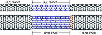 | ||
| Fig. 1 Design scheme for the flanged nanobearing with the inner tube at top and outer tube at bottom. The connection achieved by alternate heptagons-pentagons is illustrated in the portion highlighted in orange color. | ||
We carry out classical molecular dynamics simulations of the flanged nanobearing using a microcanonical ensemble. In all our simulations, the shaft is the rotator of the bearing and an initial angular velocity is ascribed to every atom of the shaft. Three atoms at each end of the sleeve were frozen at their initial positions. Geometry optimization and dynamics calculations are performed using the Dreiding forcefield.18 Inter-tube interactions are modelled by Lennard-Jones (L-J 12–6) potential. A dynamics step size of 1 fs was used for all calculations. In order to examine high temperature operation of the bearing, molecular dynamics calculations are first performed within canonical ensemble for 300 ps. The resulting thermally equilibrated configuration is then used as the input to further dynamics using a microcanonical ensemble. A simple nanobearing constructed from (4,4)/(9,9) DWNT with both the tubes of length 9.95 nm is examined along the same line for comparison purposes.
3 Results and discussion
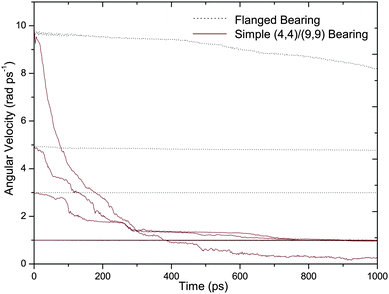
Bearing characteristics have been studied upon subjecting the shaft to different initial intertube angular velocities ω. For the simulation duration of 1 ns, Fig. 2(a) displays angular velocity dampening for various initial velocities (ω = 1, 3, 5 and 10 rad/ps). The simple (4,4)/(9,9) bearing enters a strongly dissipative regime for all initial velocities except at ω = 1 rad/ps. This is comparable with results from previous studies indicating a smooth rotation for perfect (5/5)/(10,10) bearings below 0.75 rad/ps.9 The flanged bearing, on the other hand, maintains its angular velocity without any appreciable dissipation until ω = 5 rad/ps suggesting near-frictionless bearing behavior. Even at an extremely high initial angular velocity of 10 rad/ps, the flanged bearing shows weak energy dissipation. Only 14% reduction in its initial angular velocity occurs as compared to 98.5% slowdown of (4,4)/(9,9) bearing. It is apparent that with no pre-simulation heating, the simple (4,4)/(9,9) bearing operates smoothly when ω is less than 1 rad/ps. Flanged bearing in comparison, exhibits a significantly higher threshold at which discernible dissipation commences. Results extend in quite similar ways, when the bearing is tested at an elevated pre-simulation temperature of 300 K. In the high temperature operation, the shaft rotations are damped faster for both the simple bearing and the flanged bearing as shown in Fig. 2(b). Due to increased thermal energy, the (4,4)/(9,9) bearing enters the dissipative regime even for ω = 1 rad/ps. However, the flanged bearing maintains angular velocity appreciably up to ω = 5 rad/ps. Rotational stability at high speeds as well as high temperatures is thus evident of the amelioration brought about by the structural manipulation in creating the flanged bearing.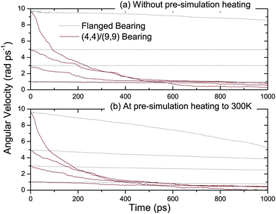 | ||
| Fig. 2 Angular velocity dissipation for flanged bearing (dashed line) and (4,4)/(9,9) bearing (continuous line) with initial angular velocity as 1 rad/ps, 3 rad/ps, 5 rad/ps and 10 rad/ps. (a) Top and (b) bottom panels show the results with no pre-simulation heating and with 300 K pre-simulation temperature respectively. | ||
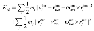
As the inner tube starts to rotate, the rotational kinetic energy can be channelled into various other mechanical modes such as the intertube translational mode as well as rotation of the outer tube. In addition, a significant fraction of energy is expended to excite other high-frequency phonon modes in both tubes. Relative kinetic energy (Krel) serves as a direct measure of the disorderly phonon energy.19 After adapting the approach of Zhao et al.19 so as to appropriately take into account the rotational motion, the expression for Krel can be formulated as
 | (1) |
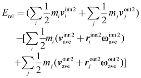
Assuming the instantaneous structure of the DWNT bearing as a rigid body, an alternative formula for relative kinetic energy (Erel) can also be proposed solely in terms of different kinetic energies.
 | (2) |
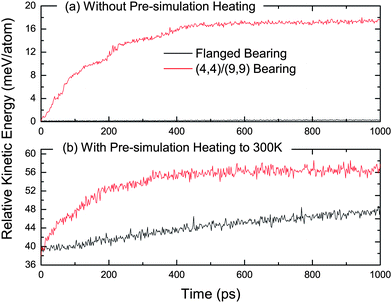 | ||
| Fig. 3 Comparison of relative kinetic energy (meV/atom) for flanged bearing and (4,4)/(9,9) bearing at ω = 5 rad/ps and (a) no pre-simulation heating, and (b) with pre-simulation heating to 300 K. | ||
Due to an intrinsic barrier against axial motion of the inner tube, the flanged bearing shows substantially less transfer from rotational energy of outer tube to the translational energy of inner tube. Inner tube of the flanged bearing is thus axially confined between a steeper potential well with respect to the axial sliding than the plain bearing as exhibited in Fig. 4. The symmetrical shoulders formed at approximately 3.6 nm displacement of inner tube are the result of crossover of the opposite end segments of inner and outer tube. As shown in the inset of Fig. 4, in comparison, the simple DWNT bearing shows pronounced axial oscillation whereas the flanged bearing oscillates in an extremely narrow range. At an elevated temperature, the atoms of the inner tube can acquire sufficient energy to overcome the sliding barrier in case of the simple bearing. This may lead to large amplitude oscillation of the shaft. At a pre-simulation temperature of 300 K, the distinction between simple and flanged bearings is observed to fade. However, due to the steeper potential well in which the inner tube of flanged bearing resides, even at high pre-simulation temperature, restriction on axial motion is still preserved considerably. When the inner tube acquires translational motion, the system can be viewed upon as simultaneously an oscillator and a bearing. On one hand, initiation of axial motion may have its origin in temperature effects or in the energy drawn from the rotational kinetic energy component. The latter case itself will lead to a reduction in the angular speed of the shaft. Furthermore, regardless of its origin, oscillatory motion may excite more phonons under suitable circumstances. Effectively obstructing this energy leakage path, the flanged bearing shows better prospects than the simple bearing.
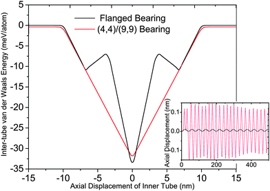 | ||
| Fig. 4 Inter-tube van der Waals potential energy variation against relative axial sliding for flanged bearing and (4,4)/(9,9) bearing. Inset shows axial oscillation of inner tube for both types of bearings when ω = 3 rad/ps. | ||
In an alternative view, the flanged bearing structure can be considered as the sandwiched (4,4)/(9,9) DWNT bearing between two (8,0)/(18,0) DWNT bearings. The (8,0)/(18,0) segments have the calculated inter-tube distance of about 0.39 nm which is higher than the equilibrium distance of 0.34 nm between adjacent tubes in a MWNT. It is interesting to note that these end parts may play a dually important role in the design of the flanged bearing. As a result of larger inter-tube separation, the van der Waals interaction between the two tubes is small and is reflected in extremely shallow corrugation against rotation leading to smoother motion. On the other hand, the inter-tube distance is not large enough to alter the symmetry of the DWNT bearing thereby providing it axial stability. It was verified that the inter tube van der Waals potential energy strikes a minimum with both the tubes coaxially placed. Both of these factors indicate that (8,0)/(18,0) bearing itself may be a nearly frictionless device. Simulation results agree with this contention for 10nm long (8,0)/(18,0), which shows negligibly low dissipation even at ω = 10 rad/ps.
However, the larger inter tube separation for the (8,0)/(18,0) bearing has to be accounted for when considering its better performance. It is thus incumbent to further verify whether the stabilizing effect of the flanged bearing stems in the existence of (8,0)/(18,0) segments, or is purely a result of its unique structure. This is achieved through keeping the inherent structure of the original flanged bearing the same, and reducing the lengths of each of the (8,0)/(18,0) flange segments to only 1 nm. Overall, this has the effect of making the central 4 nm long (4,4)/(9,9) system as the primary rotator while decimating the effect of longer flanges. Similar to the previous observation, Fig. 5 depicts that both types of shortened bearings have similar characteristics only for ω = 1 rad/ps. Above that, however, the flanged bearing is clearly superior at maintaining its angular velocity when compared to the simple (4,4)/(9,9) bearing, which is attributed to its shouldered structure.
 | ||
| Fig. 5 Angular velocity dampening as a function of time for the flanged bearing (dashed line) and the (4,4)/(9,9) bearing (continuous line) without any pre-simulation heating. Both the bearings are nearly 6 nm in length. | ||
The flanged bearing structure rests its merit on the interlocking provided by the shouldered joints. It thus also demands evaluation in the event of minor design imperfections. Instead of having the junctions for both the inner and the outer tube precisely at the same transverse plane, we consider slightly displaced location of the junctions for the inner tube. In the new configuration, the (4,4) CNT segment of the inner tube is used with the length of 4.7 nm. As a result, this new structure provides a small axial relief of about 0.35 nm. The van der Waals interaction energy surface is thus flattened for a narrow range of axial displacement of the shaft about the equilibrium position. While this modification still exhibits the similarly steep potential well as the original structure, a small clearance for axial motion is also provided. Interestingly, after subjecting the new structure to the rotational bearing simulations, angular velocity of the shaft is found to be maintained in exactly the similar manner as with the original structure. The axial clearance allowed is similar in magnitude to the equilibrium inter-tube distance of 0.34 nm of a DWNT. This may have served towards the preservation of the gist of the structural modification. It is however, possible that the very advantage of the lock-down may be squandered if the given clearance is too large. The results highlight the robustness of the flanged bearing and the properties improvement.
We further note that maintaining the co-axiallity of different tubes is essential for the flanged structure to be able to perform as a device. This restricts the selection of connecting tubes to only the armchair and zigzag nanotubes with further due considerations to keeping the inter-tube distance as close to 0.34 nm as possible.
Recently, synthesis techniques with a control over diameter of a SWNT during its growth period have started to emerge. One such method, the “temperature mediated” CVDgrowth method devised by Yao et al. demonstrated that an increase (decrease) of process temperature leads to a corresponding decrease (increase) in the diameter of SWNT during its growth creating a junction.20,21 Speculatively, this method may pave way for DWNT generation with precise control over diameter shift. A compound DWNT structure, similar to the proposed flanged bearing in this paper might then be visualized to result from the timed reversals of temperature from a lower value to higher and back to lower again.
4. Conclusion
A new design of DWNT based nanobearing is introduced. The individual tubes of a double-walled, flanged nanobearing are designed via connections of appropriately selected SWNTs of marginally differing diameters. We demonstrate that such a structural modification offers a steeper potential well for the inner tube to reside in as compared to simple DWNT based structures. The features of the flanged nanobearing have been shown to significantly better the performance via inhibition of large amplitude axial motion of the rotator. Low energy dissipation and wider operating regime have been shown to be characteristic to the flanged structure of the bearing.References
- J. Cumings and A. Zettl, Science, 2000, 289, 602–604 CrossRef.
- G. D. R. Saito and M. S. Dresselhaus, Physical Properties of Carbon Nanotubes, Imperial College Press, London, U.K., 1998 Search PubMed.
- H. Somada, S. K. Hirahara, Akita and Y. Nakayama, Nano Lett., 2009, 9, 62–65 CrossRef CAS.
- B. Bourlon, D. C. Glattli, C. Miko, L. Forro and A. Bachtold, Nano Lett., 2004, 4, 709–712 CrossRef CAS.
- A. M. Fennimore, T. D. Yuzvinsky, W.-Q. Han, M. S. Fuhrer, J. Cumings and A. Zettl, Nature, 2003, 424, 408–410 CrossRef CAS.
- A. Barreiro, R. Rurali, E. R. Hernàndez, J. Moser, T. Pichler, L. Forrò and A. Bachtold, Science, 2008, 320, 775–778 CrossRef CAS.
- S. Zhang, W. K. Liu and R. S. Ruoff, Nano Lett., 2004, 4, 293–297 CrossRef CAS.
- J. Servantie and P. Gaspard, Phys. Rev. Lett., 2006, 97, 186106–09 CrossRef CAS.
- C. Z. Zhu, W. L. Guo and T. X. Yu, Nanotechnology, 2008, 19, 465703–07 CrossRef.
- B. E. Zhu, Z. Y. Pan, Y. X. Wang and Y. Xiao, Nanotechnology, 2008, 19, 495708–12 CrossRef.
- Y. Zhao, C. C. Ma, L. H. Wong, G. H. Chen, Z. P. Xu, Q. S. Zheng, Q. Jiang and A. T. Chwang, Nanotechnology, 2006, 17, 1032–1035 CrossRef.
- L. H. Wong, Y. Zhao, G. H. Chen and A. T. Chwang, Appl. Phys. Lett., 2006, 88, 183107–09 CrossRef.
- H.-Y. Song and X.-W. Zha, Phys. Lett. A, 2009, 373, 1058–61 CrossRef CAS.
- Z. P. Xu, Q.-S. Zheng and G. H. Chen, Phys. Rev. B, 2007, 75, 195445–49 CrossRef.
- Y. Zhao, C. C. Ma, L. H. Wong, G. H. Chen, Z. P. Xu, Q. S. Zheng, Q. Jiang and A. T. Chwang, J. Comput. Theor. Nanosci., 2006, 3, 852–856 CrossRef CAS.
- Q.-W. Hou, B.-Y. Cao and Z.-Y. Guo, Nanotechnology, 2009, 20, 495503–10 CrossRef.
- A. Rochefort and P. Avouris, Nano Lett., 2002, 2, 253–256 CrossRef CAS.
- S. L. Mayo, B. D. Olafson and W. A. Goddard, J. Phys. Chem., 1990, 94, 8897–8909 CrossRef CAS.
- Y. Zhao, C. C. Ma, G. H. Chen and Q. Jiang, Phys. Rev. Lett., 2003, 91, 175504–07 CrossRef.
- Y. Yao, Q. Li, J. Zhang, R. Liu, L. Jiao, Y. T. Zhu and Z. Liu, Nat. Mater., 2007, 6, 293–296 CrossRef.
- Y. G. Yao, X. C. Dai, R. Liu, J. Zhang and Z. F. Liu, J. Phys. Chem. C, 2009, 113, 13051–59 CrossRef CAS.
| This journal is © The Royal Society of Chemistry 2010 |