Ultrasound-driven design of metal surface nanofoams†
Ekaterina V.
Skorb
*a,
Dmitry G.
Shchukin
a,
Helmuth
Möhwald
a and
Daria V.
Andreeva
b
aMax Planck Institute of Colloids and Interfaces, Am Mühlenberg 1, Golm/Potsdam 14476, Germany. E-mail: skorb@mpikg.mpg.de; Fax: +49 567331 9202; Tel: +49 576331 9404
bPhysical Chemistry II, University of Bayreuth, Universitatstr., 30, Bayreuth 95440, Germany
First published on 19th April 2010
Abstract
Ultrasound processes are particularly interesting for a great variety of applications like formation of developed surfaces, finishing, catalyst formation, polymerization and surface polymer attachment, etc. Here, we report on the ultrasound-driven formation of metal surface nanofoams in aqueous media. Systematic investigation of ultrasound effects on various types of aluminium, iron and magnesium alloys shows that the character of the metal determines the roughness of the metal surface. A trick with attachment of layered double hydroxide laurate to a nanostructured aluminium-based foam surface results in the formation of a corrosion-resistant superhydrophobic surface.
Introduction
Metal nanofoams are of great interest in various industrial sectors – automotive, aerospace, machine construction, etc. – as well as for functional applications. Various manufacturing processes are used for their construction, however, the majority of them are expensive and time consuming and it is important to find an alternative effective method for metal nanofoam formation.1–4Ultrasonic irradiation differs from traditional energy sources (such as heat, light, or ionizing radiation) in duration, pressure, and energy per molecule. The chemical and physical effects of ultrasound are driven by acoustic cavitation: the growth, oscillation and collapse of microbubbles in the medium. Short-lived, localized hot spots in a cold liquid produced by cavitation are characterized by temperatures of ca. 5000 K, pressures of about 1000 atmospheres, lifetimes considerably less than a microsecond, and heating and cooling rates above 1010 K per second. When cavitation occurs in a liquid near a solid surface, the dynamics of the cavity collapse change dramatically. In pure liquids, the cavity remains spherical during collapse because its surroundings are uniform. However, near a solid surface the cavity collapse is very asymmetric and generates high-speed jets of liquid.5–11
High-intensity ultrasound irradiation has been used for a long time in metal technology including metal crystallization,12 forming13 and finishing.14 The application of ultrasound to a metal melt generally leads to metals with improved grain refinement and homogeneity.15 In our previous work, we demonstrated that the controlled ultrasonic treatment of aluminium alloy plates leads to formation of a rough metal surface providing very good adhesion of anticorrosion protective coatings. We showed that the collapse of cavitation bubbles near aluminium surface causes: i) surface cleaning (destruction and removal of impurities); ii) significant increase in the roughness of the interfacial layer and, therefore, adhesion of polyelectrolytes to the surface and iii) overlapping developed aluminium structures.16,17 However the mechanism of sonochemical metal plate modification was not investigated for a wide spectrum of metals and some important properties of the resulting surfaces remains unstudied. Thus here, we systematically study the effect of ultrasound irradiation (intensity up to 57 W cm−2) on the surface morphology and properties (wettability, adhesion and corrosion resistance) of different metal alloys. Aluminium, magnesium and iron alloys were used to demonstrate the versatility of the novel approach to surface treatment. The current research provides a deep understanding of the mechanisms and promotes the application of an environmentally friendly ultrasonic technology. Since ultrasonic treatment is not an exotic process and applicable even on a large scale in industrial manufacturing, controlling the process may lead to new applications making use of the specially designed surface.
Results and disscussion
The effect of ultrasound in material science arises from the interplay of conceptually different mechanisms: (1) physical impact due to a pressure wave and a jet imprinting on the metal surface and (2) the extreme temperatures and pressures creating highly reactive radicals derived from water and oxygen having a chemical impact on the metal surface.6,11,18Fig. 1 schematically illustrates the ultrasound-driven modification of metal plates. | ||
| Fig. 1 Scheme of the ultrasound-driven design of metal surface nanofoams: (a) the physical effect on the metal surface and (b) the chemical effect providing the formation of a developed metal surface nanofoam structure (c). | ||
The first stage (Fig. 1a) is jet imprinting on the metal surface. During this stage the initial protective layer of oxide which covers the metal surface is destroyed. The metals which were analyzed differ in their melting points, since during this stage some local heating of the surface also takes place. We suppose that the metals with lower melting points should be more sensitive to the influence of jets, thus during the first stage we expect that the modification of magnesium should be faster in comparison with aluminium and iron and the modification of aluminium faster than iron. The second stage (Fig. 1b) relies on chemical impact and metal oxidation ability. Highly reactive radicals derived from water and oxygen (active oxygen species) begin to modify the unprotected surface which was formed by the jets, simultaneously the new porous structure is stabilized due to the formation of a novel protective layer. The expectation was to see the following metal sensitivity: magnesium as the most reactive should form the more developed surface the fastest, aluminium should be after magnesium and iron should have the lowest speed of modification. The last stage (Fig. 1c) is the stabilization of the formed porous structure. It should be also noted that all process are extremely fast and difficult to be study separately, thus just the variation in the spectrum of the studied metal could help to draw conclusions.
Metal surfaces were modified by sonication of 1 × 2 cm metal plates in 40 ml of purified water. Each metal plate was irradiated separately from the others for different times and intensities of sonication at 1 cm distance from the sonotrode. The sonotrode was a vertical rod immersed in water and the metal plate was immediately below it. The reaction temperature was kept at 65 °C by a thermostatic cell. The SEM images (Fig. 2a–c) of metal surfaces sonicated at 57 W cm−2 indicate the formation of highly developed metal nanofoam surfaces. Three commercially important alloys based on aluminium (Fig. 2a) magnesium (Fig. 2b) and iron (Fig. 2c) were used. The difference in surface morphology after sonication is caused by different chemical (surface oxidation by free radicals) and physical (melting points, durability) properties and, therefore, different interfacial responses to cavitation. It is worth to say that our assumptions were right and the modification of the magnesium was the fastest, aluminium showed the middle speed of modification and the lowest speed of modification was observed for steel (Fig. S1 of the ESI†). Since the magnesium modification is the fastest and a mechanism is more difficult to be study in progress and to compare with iron, we further analyzed and compared aluminium (the same tendency as magnesium to be modified by jets and also high oxidation ability with middle speed of modification which makes it easier to be studied) and iron.
 | ||
| Fig. 2 SEM images of (a) aluminium, (b) magnesium alloys and (c) stainless steel after 40 min sonication at 57 W cm−2. | ||
In Fig. 3a it can be seen that sonication of a metal surface at high intensity results in a drastic increase of surface roughness (Rms). Rms increases from 13 to 118 nm in 60 min for aluminium and from 18 to 211 nm for steel, which is in good agreement with SEM data.
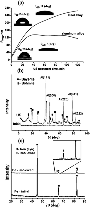 | ||
| Fig. 3 Influence of sonication time on plate roughness (a), insets show the water contact angles of the surface before and after sonication (57 W cm−2, 60 min). XRD patterns of (b) aluminium and (c) iron before and after sonication (57 W cm−2, 40 min). | ||
However, the dependence of the roughness on the time of irradiation differs for different metals. There is an increase in roughness of a steel surface throughout the period of modification, in contrast, in the case of aluminium, the roughness reaches the highest value within 30 min and after that it shows a tendency to slightly decrease. These differences can be attributed to the different factors which play a significant role in ultrasound-driven surface modification. In the case of aluminium the chemical and physical effects are involved in ultrasound-driven alloy modification and the modification in this case goes faster, but in the case of steel the more important role is attributed to the physical effects and modification proceeds slower. Thus in the case of sonochemical modification of aluminium at 57 W cm−2 for 30 min one can reach the maximum possible surface development and after that any further sonication does not result in a further surface roughness increase but in the formation of deeper oxide layers in aluminium which have the tendency to be easily destroyed at a thickness more than 200 nm. In contrast, in the case of a steel surface the roughness increases continuously during surface modification by high-intensity ultrasound because the physical process is not complementary with the chemical one.
The effect of ultrasound on the composition of alloys was studied by XRD and ED on metal powders. The XRD patterns given in Fig. 3b are evidence that bayerite Al(OH)3 (black squares in the XRD spectrum) with an admixture of boehmite AlO(OH) is formed during sonication of an aluminium alloy. The quantity of bayerite increases during formation of the porous structure which corresponds to the formation of a more developed surface of the samples. The intensity of the signals in the XRD spectrum of sonicated samples is decreased and slightly shifted due to grain destruction under ultrasound irradiation. The most stable grain corresponds to the (111) plane, the maximum density plane for a face-centered cubic structure. The observed changes are probably caused by the effect of ultrasound on grain formation and orientation. The electron microdiffraction measurements provide evidence that the foam-like interfacial nanolayer is built from highly ordered aluminium crystallites. This foam nanostructure is also visible in the TEM image (Fig. 4a). The results for the X-ray diffraction analysis of steel before and after modification (Fig. 3c) were essentially the same except that generally the three major peaks for Fe (from the steel) were visible. Simultaneously the X-ray diffraction results of the modified sample suggest that iron oxide might be present which was also confirmed by XPS measurements.
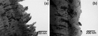 | ||
| Fig. 4 TEM images of an aluminium alloy sonochemically treated for 40 min at intensities of (a) 57 W cm−2 and (b) 30 W cm−2. | ||
The intensity and duration of ultrasound treatment dramatically influences the development of porous metal structures. Fig. 5 shows SEM images of the surfaces of aluminium plates sonicated at different intensities and for different times. Samples treated at intensities of 30 W cm−2 (Fig. 5a and c) and 57 W cm−2 (Fig. 5b and d) exhibit different surface morphologies. The morphology of the plates sonicated at 30 W cm−2 (Fig. 4b, 5a) does not show any characteristics of a nanofoam interfacial layer. The latter surface has the typical morphology of the rough aluminium oxide layer produced, for example, by anodizing. In contrast, the samples prepared at 57 W cm−2 (Fig. 5b) have the morphology of porous surface metal nanofoams. Therefore, increase of the ultrasonic power results in more intense treatment of the metal surface forming a porous metal layer on the top. The thickness of the modified layer estimated by TEM analysis of ultramicrotomed plates is about 200 nm with foam cell size ∼7 nm. The TEM image shows a mesoporous foam-like interfacial layer formed under ultrasound irradiation at 57 W cm−2. At lower intensity of sonication (30 W cm−2) we observed only a slightly increase of the surface roughness. It should be noted that the variation of the alloy composition shows that the different alloys have comparable sensitivity to the ultrasound-driven modification. It allows us to conclude that the main role in the modification ability is attributed to the main alloy component involved either by the physical or by chemical aspects of the ultrasound treatment (Fig. S2 of the ESI†).
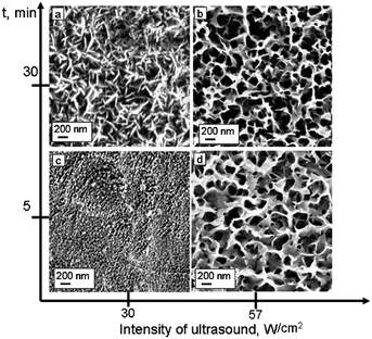 | ||
| Fig. 5 SEM images of the aluminium alloy plates after sonication at different intensities and duration: 30 min at intensity 30 W cm−2 (a); 30 min at intensity 57 W cm−2 (b); 5 min at intensity 30 W cm−2 (c); 5 min at intensity 57 W cm−2 (d). | ||
The water contact angle measurements provide evidence that the ultrasound-modified surfaces exhibit higher hydrophilicity compared to the initial one (Fig. 3a). It should be noted that the contact angle is very sensitive to the geometrical structure of a solid surface: an intrinsically hydrophobic surface becomes more hydrophobic as its roughness increases and, vice versa, the hydrophilicity shows an increase with roughness for the intrinsically hydrophilic surface. Consideration of the effect of the roughness of structures which form on metal surfaces during the sonication process, on their hydrophilicity, led to a modification of classical Young's equation:19,20
Finally, we were interested in characterization of the metal properties after sonication. The scanning vibrating electrode technique (SVET) allows measuring current density maps over the selected surface of the sample thus monitoring local cathodic and anodic activity in the corrosion zones.21–26Fig. 6 shows the monitoring of corrosion activity of a steel plate with and without ultrasound treatment, immersed into corrosive solution (0.1 M NaCl) for 12 h. We observed that an intensive corrosion process results in the development of defects throughout the whole surface of the sample finally leading to the total corruption of the unmodified steel surface (Fig. 6a and c). Fig. 6e shows the time monitoring of anodic and cathodic activity of a steel plate without ultrasound treatment (curves 1 and 4) immersed in a corrosive solution (0.1 M NaCl) for 12 h. It is seen that corrosion increases dramatically with time reaching very a high value of anodic activity ca. 300–400 μA cm−2. The steel samples after high-intensity ultrasound irradiation (Fig. 6e curve 2 and 3) exhibit dramatically different behavior. The increase in corrosion activity is insignificant, after 12 h of immersion in 0.1 M NaCl the anodic activity is ∼8 μA cm−2. We propose some important features of the sonicated steel structure: highly developed surface, dislocation and impurity removal from the surface and a more compact oxide layer formation due to a recrystallization process.
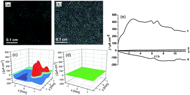 | ||
| Fig. 6 Optical microscopy images (a, b) and 3D current density maps obtained by SVET (c, d) of the scratched steel plates in a corrosion test of unmodified steel (a, c) and steel after ultrasound treatment (57 W cm−2, 60 min) (b, d). (e) Time monitoring of the anodic (curves 1 and 2) and cathodic (curves 3 and 4) activity on the steel surface before sonication (curves 1 and 4) and after sonication at 57 W cm−2 (curves 2 and 3). The samples were immersed for 12 h in 0.1 M NaCl solution. | ||
In Fig. 7a and b it can be seen that the corrosion stability of the aluminium alloy is also higher in the case of the treated samples. The aluminium plates sonicated at high intensity exhibit a very pronounced resistance to the corrosion based on monitoring the aluminium surface by SEM after stopping the corrosion test (Fig. 7). Simultaneously, SVET measurements show that anodic activity on the surface of aluminium before and after sonication treatment at 57 W cm−2 is practically the same ∼60 μA cm−2. The explanation results from the difference in corrosion mechanism for both the untreated and treated samples. Before sonication the corrosion process involves the whole surface of aluminium; in contrast, in the case of the sonicated aluminium surfaces the corrosion peak is well defined and localized on the intermetallic inclusions in the aluminium alloy. It should also be noted that some of the sonicated metal surfaces could be characterized as superhydrophilic (water contact angles for aluminium and steel 60 min sonicated at 57 W cm−2 are 7° and 11°, respectively).
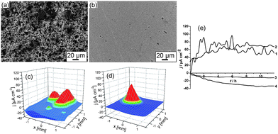 | ||
| Fig. 7 SEM images (a, b) and 3D current density maps obtained by SVET (c, d) of the aluminium plates after the corrosion test of the unmodified surface (a, c) and aluminium after ultrasound treatment (57 W cm−2, 60 min) (b, d). (e) Time monitoring of the anodic (curves 1 and 2) and cathodic (curves 3 and 4) activity on the aluminium surface before sonication (curves 1 and 4) and after sonication at 57 W cm−2 (curves 2 and 3). The samples were immersed for 12 h in 0.1 M NaCl solution. | ||
In these cases the speed of chloride ion adsorption and of the corrosion process is higher and the conditions could be determined as more aggressive in comparison with surfaces before sonication. Notwithstanding the more aggressive media the corrosion stability of the metals is higher after applying high-intensity sonication for metal modification.
However, superhydrophilicity can help in the formation superhydrophobic surfaces involving surface modification of our developed structure, for example by sodium laurate,27–29 by attachment of laurate under low-intensity sonication to the porous surface and formation of layered double hydroxide laurate. The formed structure is shown in Fig. 8.
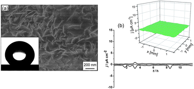 | ||
| Fig. 8 SEM image of an aluminium plate covered by layered double hydroxide laurate (a), inset shows water contact angle onto this surface. (b) Time monitoring of the anodic and cathodic activity on the aluminium surface covered by layered double hydroxide laurate, inset shows current density maps of the surface after 12 h immersion in 0.1M NaCl. | ||
Treatment by sodium laurate induced superhydrophobicity with a water contact angle of 163° (Fig. 8, inset). It the case of unmodified aluminium the layered double hydroxide layer demonstrates very poor adhesion properties. In contrast, sonicated adhesion was very high even after 1 month of the corrosion test. The SVET data of corrosion resistance (Fig. 8b) demonstrates very high corrosion resistance with simultaneous self-healing ability.28,29 3D current density map (Fig. 8b, inset) shows that there is no corrosion current above the surface detected even after 12 h of immersion in 0.1 M NaCl solution.
Conclusion
In conclusion, we have shown that highly intense ultrasound surface treatment results in the formation of highly developed hydrophilic surfaces both when chemical and physical effects are involved in surface development (aluminium and magnesium) and in the case when the physical effect plays the significant role (steel). The corrosion stability increases after high-intensity ultrasound metal surface treatment. Systematic investigation of ultrasound effects on various types of alloys shows the that character of the metal determines the roughness dependence of the metal surface on the time of irradiation as well as the ultrasound-induced metal corrosion stability. The attachment of layered double hydroxide laurate to the superhydrophilic ultrasound-formed aluminium surface results in the formation of a very corrosion stable superhydrophobic “lotus” like surface.Experimental
Sonication of AA2024 and steel plates
Metal plates (1 × 2 cm) were degreased in isopropanol flow and rinsed in purified water. Each plate was sonicated in pure water in a thermostated flow cell (FC100L1-1S) (at 65 °C temperature) with the VIP1000hd (Hielscher, Germany) operated at 20 kHz with a maximal output power of a 1000 W ultrasonic horn BS2d22 (head area of 3.8 cm2) and equipped with a booster B2-1.2. The maximum intensity was calculated to 57 W cm−2 at a mechanical amplitude of 81 μm.Attachment of layered double hydroxide laurate to pre-sonicated AA2024 plates
An aluminium alloy AA2024 plate 1 × 2 cm pre-sonicated as described above and rinsed in purified water was immersed in a 0.05 M aqueous solution of sodium laurate at 10 W cm−2 for 20 min. The resulting film was rinsed with ethanol and then dried at room temperature.X-Ray diffraction (XRD)
X-Ray diffraction of the samples was studied on a Bruker AXS – D8 ADVANCE X-ray diffractometer and on a Nanostar Bruker AXS diffractometer.X-Ray photoelectron spectroscopy (XPS)
XP spectra were acquired with a SPECS hemispherical energy analyzer (Phoibus 100) and SPECS focus 500 X-Ray monochromator using Al Kα radiation with an energy of 1486.74 eV.Microscopy studies
Scanning electron microscopy (SEM) measurements were conducted with a Gemini Leo 1550 instrument at an operating voltage of 3 keV. Samples were sputtered with gold. Transmission electron microscopy (TEM) images were obtained on a Zeiss EM 912 Omega transmission electron microscope operating at 300 kV. The samples were ultramicrotomed (Leica EM FC6) and placed onto the copper grids coated with carbon film. Atomic force microscopy (AFM) (Molecular Force Probe 1D AFM, Asylum Co, Santa Barbara, USA) was used to determine the dependence of the change of roughness on the sonication duration and intensity, before the AFM study the metal plates were subjected to grinding and polishing.Water contact angle measurements
The hydrophilic/hydrophobic properties of the plates were studied using the Contact Angle Measurement System G10 (Krüss, Germany).Scanning vibrating electrode technique (SVET)
The SVET experiments were performed by using the equipment supplied by Applicable Electronics (Forestdale, MA) (26). 4 × 4 mm2 areas were opened for the measurements, other parts of the samples were protected masking with Polyester 5 adhesive tape (3M Company). The sample was mounted in a home-made epoxy resin cell. The immersion solution was 0.1 M NaCl solution. Scans were initiated within 5 min of immersion and were collected every 2 h for the duration of the experiment, typically 20 h. Each scan consisted of 400 data points obtained on a 20 × 20 grid, with an integration time of 1 s per point. A complete scan required 10 min. The normal or z component of the measured current density in the plane of the vibrating electrode is plotted in 3D format over the scan area, with positive and negative current densities representing anodic and cathodic regions, respectively.Acknowledgements
The presented research was supported by the NanoFutur program of the German Ministry of Education and Research (BMBF), MUST EU FP7 project and Humboldt Foundation. The authors would like to thank Dmitri Fix for the help with SVET and Sven Kubala, Thomas Hannappel for XPS measurements.References
- J. Banhart, Prog. Mater. Sci., 2001, 46, 559 CrossRef CAS.
- J. Banhart, H. Stanzick, L. Helfen and T. Baumbach, Appl. Phys. Lett., 2001, 78, 1152 CrossRef CAS.
- L. Helfen, T. Baumbach, P. Pernot, P. Cloetens, H. Stanzick, K. Schladitz and J. Banhart, Appl. Phys. Lett., 2005, 86, 231907 CrossRef.
- L. Helfen, T. Baumbach, J. Banhart and H. Stanzick, in Proc. Ital. Soc. for Nondestructive Testing, 2000, 1 Search PubMed.
- L. Rayleigh, Phil. Mag., 1917, 34, 94.
- J. P. Lorimer and T. J. Mason, Chem. Soc. Rev., 1987, 16, 239 RSC.
- K. S. Suslick, Science, 1990, 247, 1439 CrossRef CAS.
- K. S. Suslick, S.-B. Chloe, A. Cichowlas and M. W. Grinstaff, Nature, 1991, 353, 414 CrossRef CAS.
- K. S. Suslick, T. Hyeon, M. Fang and A. A. Cichowlas, Mater. Sci. Eng., A, 1995, 204, 186 CrossRef.
- M. M. Mdleleni, T. Heyeon and K. S. Suslick, J. Am. Chem. Soc., 1998, 120, 6189 CrossRef CAS.
- K. S. Suslick and G. J. Price, Annu. Rev. Mater. Sci., 1999, 29, 295 CrossRef CAS.
- Chemistry with ultrasound, ed. T. J. Mason. Elsevier, London, 1990, vol. 28, p. 195 Search PubMed.
- B. Langenecker, C. W. Fountain and O. V. Janes, Metal Prog., 1964, 85, 97 Search PubMed.
- B. A. Shenoi, K. S. Indira and R. Subramanian, Metal Finish., 1979, 77, 41.
- O. V. Abramov, Ultrasonics, 1987, 25, 73 CrossRef CAS.
- D. V. Andreeva, D. Fix, D. G. Shchukin and H. Möhwald, J. Mater. Chem., 2008, 18, 1738 RSC.
- D. V. Andreeva, D. Fix, H. Möhwald and D. G. Shchukin, Adv. Mater., 2008, 20, 2789 CrossRef CAS.
- Y. Didenko and K. S. Suslick, Nature, 2002, 418, 394 CrossRef CAS.
- G. Gogniat, M. Thyssen, M. Denis, C. Pulgarin and S. Dukan, FEMS Microbiol. Lett., 2006, 258, 18 CrossRef CAS.
- E. V. Skorb, L. I. Antonouskaja, N. A. Belyasova, D. G. Shchukin and D. V. Sviridov, Appl. Catal., B, 2008, 84, 94 CrossRef CAS.
- D. He, V. J. Gelling, D. E. Tallman and G. P. Bierwagen, J. Electrochem. Soc., 2000, 147, 3661 CrossRef CAS.
- D. He, V. J. Gelling, D. E. Tallman, G. P. Bierwagen and G. G. Wallacec, J. Electrochem. Soc., 2000, 147, 3667 CrossRef CAS.
- E. V. Skorb, D. G. Shchukin, H. Möhwald and D. V. Sviridov, J. Mater. Chem., 2009, 19, 4931 RSC.
- E. V. Skorb, A. Skirtach, D. V. Sviridov, D. G. Shchukin and H. Möhwald, ACS Nano, 2009, 3, 1753 CrossRef CAS.
- D. O. Grigoriev, K. Köhler, E. V. Skorb, D. G. Shchukin and H. Möhwald, Soft Matter, 2009, 5, 1426 RSC.
- E. V. Skorb, D. Fix, D. V. Andreeva, D. G. Shchukin and H. Möhwald, Adv. Funct. Mater., 2009, 19, 2373 CrossRef CAS.
- H. Y. Chen, F. Z. Zhang, S. S. Fu and X. Duan, Adv. Mater., 2006, 18, 3089 CrossRef CAS.
- D. G. Evans and X. Duan, Chem. Commun., 2006, 485 RSC.
- F. Zhang, L. Zhao, H. Chen, S. Xu, D. G. Evans and X. Duan, Angew. Chem., 2008, 120, 2500 CrossRef.
Footnote |
| † Electronic supplementary information (ESI) available: Additional details concerning sonochemical magnesium modification as well as dependence of the sonochemical effect on the variation of the alloy composition. See DOI: 10.1039/c0nr00074d |
| This journal is © The Royal Society of Chemistry 2010 |

