One-step fabrication of porous polymeric microcage via electrified jetting†
Ying
Zhu
,
Dayong
Yang
* and
Hongwei
Ma
*
Suzhou Institute of Nano-Tech and Nano-Bionics, Chinese Academy of Sciences, Suzhou, 215125, China. E-mail: dyyang2008@sinano.ac.cn; hwma2008@sinano.ac.cn
First published on 4th May 2010
Abstract
We report a one-step method to prepare porous polymeric microcages from blend emulsion solutions via electrified jetting.
Porous materials exhibit many unique properties derived from their fantastic architectures that lead to wide applications in energy devices, drug delivery systems, catalysis, separation and tissue engineering.1,2 Following the two largest categories of porous materials (i.e. carbon3–5 and silicon6–8), polymers are the new rising star because of their diversity and availability of the raw materials, versatile properties and wide biomedical and energy applications.9,10 One grand challenge in the development of polymeric porous materials is to explore a facile and efficient fabrication strategy.
To date, structural design and fabrication of polymer hollow spheres have made significant progress. Various template methods, such as hard template,11,12 soft template13,14 and polymeric emulsion,15–17 have been demonstrated to prepare polymer hollow spheres. However, on the other hand, porous spheres usually have solid cores. Microcages with hollow core/porous shells are advantageous because they have lower density and larger surface areas than porous spheres with solid cores. But the design and fabrication of microcages were rarely achieved. As one of the rare demonstrations, Ge et al. developed a multistep protocol combining emulsion route and template method.15 Nevertheless, how to simply and effectively fabricate polymeric microcages remains a very important and challenging issue.
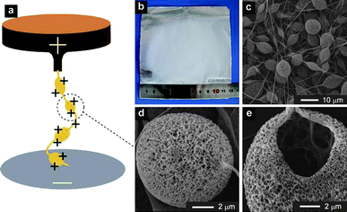
We report herein a one-step method to prepare porous polymeric microcages via electrified jetting that applies high electric field on the polymeric blend emulsion solutions. We coined electrified jetting (EJ) for this method. EJ, which also appears in documents as electrospinning or electrospray, is a well established technology that uses high electric fields to process polymer solutions into fibers or particles at the range of micro- to nano- scale.18–26 We used the conventional homemade EJ set-up as shown in Fig. 1a, but obtained very different products: microcages. A mixture of polystyrene (PS)/poly(dimethylsiloxane) (PDMS) dissolved in N,N-dimethylformamide (DMF)/tetrahydrofuran (THF) was used as the model polymeric blend emulsion solutions. The preparation process of the emulsion solution was special: PS granules were first dissolved in DMF–THF to achieve a transparent solution, followed by the addition of viscous liquid PDMS into the solution, resulting in a semi-transparent emulsion solution. EJ mats were deposited on the collector (the white part in Fig. 1b). Scanning electron microscopy (SEM) images showed the micro-morphology of microcages (Fig. 1c-e, Fig. S1a&b†): there are pores on the surface (Fig. 1d, Fig. S1a&b†); the interior is hollow (Fig. 1e); microcages are connected together by fibers to form a stable 3D network at the macro-level (Fig. 1c). Transmission electron microscopy (TEM) image further revealed the details of the porous and hollow architectures (Fig. S1c†), as compared with solid nonporous spheres made of pure PS (Fig. S1d†).
 | ||
Fig. 1 a) Schematic EJ setup. b) Image of EJ mats taken by a digital camera. c–e) Gradually enlarged SEM images of EJ mats. The experimental parameters for b–e) are: PS concentration 6%, PDMS/PS = 1![[thin space (1/6-em)]](https://www.rsc.org/images/entities/char_2009.gif) : :![[thin space (1/6-em)]](https://www.rsc.org/images/entities/char_2009.gif) 3, DMF/THF = 1 3, DMF/THF = 1![[thin space (1/6-em)]](https://www.rsc.org/images/entities/char_2009.gif) : :![[thin space (1/6-em)]](https://www.rsc.org/images/entities/char_2009.gif) 1, voltage 20 kV, and work distance 16 cm. 1, voltage 20 kV, and work distance 16 cm. | ||
We identified the composition of solutions as the most critical factor for determining the formation of microcages. Pure polymer solutions, such as PS/DMF solution, led to solid spheres (Fig. S1d†). Only emulsion solutions produced microcages. In the current study, PS and PDMS were chosen as the blend materials because of their poor compatibility in solutions. As a control, two compatible polymers, namely poly(methylmethacrylate) (PMMA) and PDMS, were blended but the solution did not yield microcages under all experimental parameters (data not shown).
To date, the main morphologies of EJ mats includes fibers and particles. Other hierarchic morphologies, such as fibers with multi-channels, could be fabricated by a specially designed EJ set-up or EJ process.27 Our initial results, however, indicated that using the simplest EJ set-up and EJ process one can obtain a new and potentially useful morphology, i.e. microcage. In order to control the morphology and explore the mechanism for the formation of microcages, we investigated and later optimized the experimental parameters that governed microcage formation. The parameters included the ratio of PDMS/PS, the ratio of DMF/THF and PS concentration.
First, we varied the ratio of PDMS/PS from 0![[thin space (1/6-em)]](https://www.rsc.org/images/entities/char_2009.gif) :
:![[thin space (1/6-em)]](https://www.rsc.org/images/entities/char_2009.gif) 1 (i.e., pure PS solution) to 3
1 (i.e., pure PS solution) to 3![[thin space (1/6-em)]](https://www.rsc.org/images/entities/char_2009.gif) :
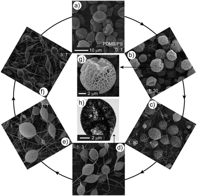
:![[thin space (1/6-em)]](https://www.rsc.org/images/entities/char_2009.gif) 1, with gradual increment of PDMS proportion. Pure PS yielded particles with nonporous surfaces (Fig. 2a) because PS/DMF/THF was a uniform solution (the solution was transparent). When PDMS/PS was in the range of 1
1, with gradual increment of PDMS proportion. Pure PS yielded particles with nonporous surfaces (Fig. 2a) because PS/DMF/THF was a uniform solution (the solution was transparent). When PDMS/PS was in the range of 1![[thin space (1/6-em)]](https://www.rsc.org/images/entities/char_2009.gif) :
:![[thin space (1/6-em)]](https://www.rsc.org/images/entities/char_2009.gif) 10∼1
10∼1![[thin space (1/6-em)]](https://www.rsc.org/images/entities/char_2009.gif) :
:![[thin space (1/6-em)]](https://www.rsc.org/images/entities/char_2009.gif) 1, microcages formed (Fig. 2c-e). But excessive PDMS, such as PDMS/PS = 3
1, microcages formed (Fig. 2c-e). But excessive PDMS, such as PDMS/PS = 3![[thin space (1/6-em)]](https://www.rsc.org/images/entities/char_2009.gif) :
:![[thin space (1/6-em)]](https://www.rsc.org/images/entities/char_2009.gif) 1, yielded nonporous and clammy materials (Fig. 2f). Interestingly, Janus particles formed when PDMS/PS = 1
1, yielded nonporous and clammy materials (Fig. 2f). Interestingly, Janus particles formed when PDMS/PS = 1![[thin space (1/6-em)]](https://www.rsc.org/images/entities/char_2009.gif) :
:![[thin space (1/6-em)]](https://www.rsc.org/images/entities/char_2009.gif) 30: one side was porous like the surface of a microcage, while other side has much smaller holes on the surface (Fig. 2b, 2g and Fig. S2†). We considered these Janus particles as a transitional state between nonporous and porous materials. A representative TEM image of the microcage (Fig. 2h) also showed the porous and hollow nature of the microcage.
30: one side was porous like the surface of a microcage, while other side has much smaller holes on the surface (Fig. 2b, 2g and Fig. S2†). We considered these Janus particles as a transitional state between nonporous and porous materials. A representative TEM image of the microcage (Fig. 2h) also showed the porous and hollow nature of the microcage.
 | ||
Fig. 2 The influence of the weight ratio of PDMS/PS on the formation of microcages. a–f) SEM images of EJ mats with different PDMS/PS ratios (the ratios are marked on the corresponding SEM images). g) A representative enlarged SEM image of b). h) A representative TEM image of microcages. a–f) share the same scale bar. The other experimental parameters are: PS concentration 6%, DMF/THF = 1![[thin space (1/6-em)]](https://www.rsc.org/images/entities/char_2009.gif) : :![[thin space (1/6-em)]](https://www.rsc.org/images/entities/char_2009.gif) 1, voltage 20 kV, and work distance 16 cm. 1, voltage 20 kV, and work distance 16 cm. | ||
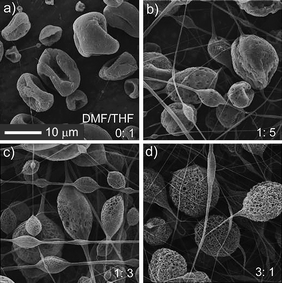
Second, we varied the ratio of DMF/THF to investigate the effect of the component of solvent. The solubility parameter δ was employed to qualitatively evaluate the compatibility between PDMS/PS and DMF/THF. THF was a good solvent for both PDMS and PS because δ of THF (9.5) was close to that of PDMS (7.3–7.6) and PS (8.7–9.1), while DMF (12.1) was not compatible with PDMS and PS. Therefore, the solution of PDMS/PS dissolved in pure THF yielded nonporous particles (Fig. 3a) due to the good compatibility between PDMS, PS and THF. After increasing the volume of DMF, pores on the surface of particles appeared (Fig. 3b, DMF/THF = 1![[thin space (1/6-em)]](https://www.rsc.org/images/entities/char_2009.gif) :
:![[thin space (1/6-em)]](https://www.rsc.org/images/entities/char_2009.gif) 5), and further increase of DMF yielded more pores (Fig. 3c, DMF/THF = 1
5), and further increase of DMF yielded more pores (Fig. 3c, DMF/THF = 1![[thin space (1/6-em)]](https://www.rsc.org/images/entities/char_2009.gif) :
:![[thin space (1/6-em)]](https://www.rsc.org/images/entities/char_2009.gif) 3). When DMF/THF was 1
3). When DMF/THF was 1![[thin space (1/6-em)]](https://www.rsc.org/images/entities/char_2009.gif) :
:![[thin space (1/6-em)]](https://www.rsc.org/images/entities/char_2009.gif) 1∼3
1∼3![[thin space (1/6-em)]](https://www.rsc.org/images/entities/char_2009.gif) :
:![[thin space (1/6-em)]](https://www.rsc.org/images/entities/char_2009.gif) 1, microcages formed (Fig. 1c-e, Fig. 3d). If the volume of DMF was excessive (such as DMF/THF = 4
1, microcages formed (Fig. 1c-e, Fig. 3d). If the volume of DMF was excessive (such as DMF/THF = 4![[thin space (1/6-em)]](https://www.rsc.org/images/entities/char_2009.gif) :
:![[thin space (1/6-em)]](https://www.rsc.org/images/entities/char_2009.gif) 1), PDMS could not completely dissolve into the solution.
1), PDMS could not completely dissolve into the solution.
 | ||
Fig. 3 The influence of solvent composition on the formation of microcages. a–d) SEM images of EJ mats with different DMF/THF ratios (the ratios are marked on the corresponding SEM images). a–d) share the same scale bar. The other experimental parameters are: PS concentration 6%, PDMS/PS = 1![[thin space (1/6-em)]](https://www.rsc.org/images/entities/char_2009.gif) : :![[thin space (1/6-em)]](https://www.rsc.org/images/entities/char_2009.gif) 3, voltage 20 kV, and work distance 16 cm. 3, voltage 20 kV, and work distance 16 cm. | ||
Third, we investigated the effect of polymer concentration. In conventional EJ, low concentration yielded particles, and high concentration produced fibers.8 This rule was also applicable to our system. Moreover, in our system, PS concentration additionally influenced microcage formation. Low PS concentration gave birth to nonporous particles (Fig. S3a–c†). When PS concentration was 6∼10%, microcages formed, but the proportion of microcage in the EJ mats decreased with the increase of PS concentration (Fig. S3d–i†). Higher PS concentrations (such as 12%) yielded fibers with nonporous structures and no microcages. We also tested other experimental parameters such as voltage and work distance. These two parameters had negligible influence on microcage formation. After a systematic investigation, we optimized the experimental parameters for fabricating microcages: PS 6%, PDMS/PS 1![[thin space (1/6-em)]](https://www.rsc.org/images/entities/char_2009.gif) :
:![[thin space (1/6-em)]](https://www.rsc.org/images/entities/char_2009.gif) 3, DMF/THF 1
3, DMF/THF 1![[thin space (1/6-em)]](https://www.rsc.org/images/entities/char_2009.gif) :
:![[thin space (1/6-em)]](https://www.rsc.org/images/entities/char_2009.gif) 1, voltage 20 kV, and work distance 16 cm.
1, voltage 20 kV, and work distance 16 cm.
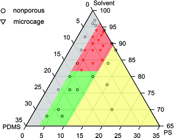
To better understand the relation between experimental parameters and morphology of EJ mats, we sketched a ternary phase diagram in Fig. 4 (detailed description is shown in Fig. S4†). In the grey area, low PS content could not provide sufficient chain entanglements so the EJ mats were nonporous particles. In the green area, PDMS content was too high (15∼30%), the surface of EJ mats was smooth and clammy because of the viscous nature of PDMS with a low molecular weight. In the yellow area, PS content was larger than 10% and EJ mats were fibers. Only well tailored PDMS/PS/solvent ingredients gave birth to microcages (red area).
 | ||
| Fig. 4 Ternary phase diagram constructed from the relative content of PDMS/PS/solvent and morphology of EJ mats. Grey: low PS content, nonporous particles (e.g., Fig. S2a†); green: high PDMS content, smooth and clammy surface (Fig. 2f); red: microcages (Fig. 1); yellow: high PS content, fiber. The triangles and circles in the diagram represent solution ingredients we've used in our experiments. | ||
Based on the aforementioned observation, we proposed a mechanism for microcage formation. The prerequisite was that the solution should be an emulsion. In the current model system, the PDMS/PS/DMF/THF mixture solution formed an emulsion, with an evidential observation that the emulsion was semi-transparent. The second important factor was the EJ process. During EJ, solvent evaporated quickly, and this resulted in phase separation. Phase separation was the direct reason for microcage formation. It should be noted that not all emulsion solutions can yield microcages, but only solutions with well tailored ingredients can yield microcages, for which phase separation occurs when solvent evaporates. Although we cannot find general underlying rules responsible for microcage formation at this stage, we believe that one can fabricate microcage structures from other emulsion systems based on our investigation.
In conclusion, we have developed a one-step method to fabricate microcages that uses EJ technology to process emulsion solutions. Compared with previous methods, our method shows the following advantages: i) the set-up is simple and cost-effective; ii) the process is facile, and only needs one step; iii) the protocol is repeatable and reliable. Previously reported microcages are independent spheres, while our microcages are connected by fibers, so as to form a 3D network at the macro-level. The 3D web makes the microcages more stable than independent spheres, which will cater for the applications of microcages used as support materials where mechanical stability is highly desired. Given the simplicity and feasibility of the EJ method, and the unique hierarchy micro/nano construction, we believe the method will be general for fabricating microcages, and thus microcages will find more applications.
Acknowledgements
This project was supported by the National Science Foundation of China (20904037) and the Natural Science Foundation of Jiangsu Province (BK2009141) with a grant to D. Y., and 100 Talents Program of CAS (08BM031001) with a grant to H. M. We thank the Public Center for Characterization and Test at SINANO. We thank Mr Mengmeng Li and Mr Pengfei Zhang for helpful discussion.Notes and reference
- M. E. Davis, Nature, 2002, 417, 813 CrossRef CAS.
- A. Stein, Adv. Mater., 2003, 15, 763 CrossRef CAS.
- J. Lee, J. Kim and T. Hyeon, Adv. Mater., 2006, 18, 2073 CrossRef CAS.
- C. D. Liang, Z. J. Li and S. Dai, Angew. Chem., Int. Ed., 2008, 47, 3696 CrossRef CAS.
- A. Stein, Z. Y. Wang and M. A. Fierke, Adv. Mater., 2009, 21, 265 CrossRef CAS.
- M. P. Stewart and J. M. Buriak, Adv. Mater., 2000, 12, 859 CrossRef CAS.
- J. M. Lim, G. R. Yi, J. H. Moon, C. J. Heo and S. M. Yang, Langmuir, 2007, 23, 7981 CrossRef CAS.
- D. Y. Zhao, J. L. Feng, Q. S. Huo, N. Melosh, G. H. Fredrickson, B. F. Chmelka and G. D. Stucky, Science, 1998, 279, 548 CrossRef CAS.
- S. Kitagawa, R. Kitaura and S. Noro, Angew. Chem., Int. Ed., 2004, 43, 2334 CrossRef CAS.
- A. Thomas, P. Kuhn, J. Weber, M. M. Titirici and M. Antonietti, Macromol. Rapid Commun., 2009, 30, 221 CrossRef CAS.
- K. Kamata, Y. Lu and Y. N. Xia, J. Am. Chem. Soc., 2003, 125, 2384 CrossRef CAS.
- S. M. Marinakos, J. P. Novak, L. C. Brousseau, A. B. House, E. M. Edeki, J. C. Feldhaus and D. L. Feldheim, J. Am. Chem. Soc., 1999, 121, 8518 CrossRef CAS.
- Y. X. Wang, Z. B. Qiu and W. T. Wang, Macromol. Rapid Commun., 2006, 27, 284 CrossRef CAS.
- Z. X. Wei and M. X. Wan, Adv. Mater., 2002, 14, 1314 CrossRef CAS.
- X. D. He, X. W. Ge, H. R. Liu, M. Z. Wang and Z. C. Zhang, Chem. Mater., 2005, 17, 5891 CrossRef CAS.
- H. Lv, Q. Lin, K. Zhang, K. Yu, T. J. Yao, X. H. Zhang, J. H. Zhang and B. Yang, Langmuir, 2008, 24, 13736 CrossRef CAS.
- G. Z. Zhang, A. Z. Niu, S. F. Peng, M. Jiang, Y. F. Tu, M. Li and C. Wu, Acc. Chem. Res., 2001, 34, 249 CrossRef CAS.
- J. Doshi and D. H. Reneker, J. Electrost., 1995, 35, 151 CrossRef CAS.
- A. Greiner and J. H. Wendorff, Angew. Chem., Int. Ed., 2007, 46, 5670 CrossRef CAS.
- Y. Jin, D. Y. Yang, D. Y. Kang and X. Y. Jiang, Langmuir, 2010, 26, 1186 CrossRef CAS.
- D. Li and Y. N. Xia, Adv. Mater., 2004, 16, 1151 CrossRef CAS.
- Y. Y. Liu, D. Y. Yang, T. Yu and X. Y. Jiang, Electrophoresis, 2009, 30, 3269 CrossRef CAS.
- D. Y. Yang, B. Lu, Y. Zhao and X. Y. Jiang, Adv. Mater., 2007, 19, 3702 CrossRef CAS.
- D. Y. Yang, X. Niu, Y. Y. Liu, Y. Wang, X. Gu, L. S. Song, R. Zhao, L. Y. Ma, Y. M. Shao and X. Y. Jiang, Adv. Mater., 2008, 20, 4770 CrossRef CAS.
- D. Y. Yang, Y. Wang, D. Z. Zhang, Y. Y. Liu and X. Y. Jiang, Chin. Sci. Bull., 2009, 54, 2911 CrossRef CAS.
- M. M. Li, D. Y. Yang, Y. Z. Long and H. W. Ma, Nanoscale, 2010, 2, 218 RSC.
- Y. Zhao, X. Y. Cao and L. Jiang, J. Am. Chem. Soc., 2007, 129, 764 CrossRef CAS.
Footnote |
| † Electronic supplementary information (ESI) available: Experimental details and Fig. S1, S2 and S3. See DOI: 10.1039/c0nr00081g |
| This journal is © The Royal Society of Chemistry 2010 |
