Selective detection of trace amount of Cu2+ using semiconductor nanoparticles in photoelectrochemical analysis†
Guang-Li
Wang
,
Jing-Juan
Xu
* and
Hong-Yuan
Chen
Key Laboratory of Analytical Chemistry for Life Science (Ministry of Education of China), School of Chemistry and Chemical Engineering, Nanjing University, Nanjing, 210093, China. E-mail: xujj@nju.edu.cn; Fax: +86-25-83597294; Tel: +86-25-83597294
First published on 7th May 2010
Abstract
A highly sensitive and selective photoelectrochemical sensor for Cu2+ was developed based on the selective interaction between CdS quantum dots (QDs) immobilized on an indium tin oxide (ITO) electrode surface and Cu2+ in a triethanolamine (TEA) solution to form CuxS-doped CdS QDs, which disrupts the electron transfer from the conduction band of CdS to ITO and results in a decrease of photocurrent.
Following recent advances in the growing field of nanotechnology, nanomaterials can be designed as exquisitely sensitive nanosensors. The interaction between the target analyte and nanomaterial is designed to produce a physicochemical perturbation on the nanosensor that can be converted into a measurable effect such as an optical or electrical signal.1 Nanomaterials have unique properties that offer a significant advantage for sensing applications. And the design of elegant assembled nanosensors is demonstrated to be an extremely powerful tool for the detection of the target analytes using various detection methods such as electrochemistry,2–5 fluorescence,6–9 electrochemiluminescence10–12etc.
Photoelectrochemistry is a newly developed analytical method13 that is expected to have the advantages of both fluorescence and electrochemical sensors.14 In addition, the electronic detection makes its instrumentation simpler, low cost and easier to miniaturize than all optical detection methods. The emergence of nanomaterials also provides new opportunity for the development of photoelectrochemical sensors.
Besides their excellent fluorescence15 and electrochemiluminescence16 properties, quantum dots (QDs) are also important photoelectrochemically active materials with the most remarkable properties of high photo-to-current conversion efficiency, size-dependent photoelectrochemical response and generation of multiple charge carriers with a single photon. As a result, QD-based photoelectrochemical assay is also gaining increasing attention. For example, on the basis of the reaction between photogenerated holes of illuminated CdS QDs and the substrate of acetylcholine esterase, the first example of a photoelectrochemical biosensor was developed for sensing enzyme inhibitors.17 Using triethanolamine as an electron donor, CdS QDs were used as labels for detection of photoelectrochemical tyrosinase activity with higher sensitivity than that of electrochemistry.18 Our group found that ascorbic acid could be used as an efficient electron donor under mild solution medium, based on which highly sensitive and label-free immunosensors were developed.19,20
Here, we have designed a new type of QD-based photoelectrochemical sensor for Cu2+. The sensing mechanism is based on the selective interaction between CdS QDs immobilized on an indium tin oxide (ITO) electrode surface and Cu2+ in a triethanolamine (TEA) solution to form CuxS-doped CdS QDs, which disrupts the electron transfer from the conduction band of CdS to ITO and results in a decrease of photocurrent. The nanosensor has its merits of high sensitivity as well as good selectivity. To the best of our knowledge, ion sensing based on the photoelectrochemical property of QDs has not been reported yet. The photoelectrochemical sensor for Cu2+ based on the change of the surface state of QDs should open new perspectives for the application of QD-based sensors for direct detection of other ions or molecules.
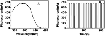
CdS QDs were prepared in water using TGA as a capping agent.21 The particle size of the TGA-capped CdS QDs was about 3.4 nm calculated from the absorption peak position in the absorption spectrum (see Fig. S1 in the ESI†).22 The negatively charged CdS QDs were electrostatically assembled on an indium tin oxide (ITO) electrode through the oppositely charged polyelectrolytes poly(dimethyldiallylammonium chloride) (PDDA). When the CdS QDs absorb photons with energies higher than that of their band gap, electrons are excited from the valence band (VB) to the conduction band (CB), forming the electron–hole pairs. Once the process happened, the electron–hole pairs would recombine or the charges would be transferred. The electron transfers to the ITO electrode and generates photocurrent because the energy level of the conduction band of ITO is lower than that of CdS.23,24 For CdS QDs, there exists a corrosion process (lattice dissolution) under illumination: 2h+ + CdS → Cd2+ + S, if there is no electron donor for scavenging the holes.25 Thus, in order to avoid photodissolution of CdS as well as to obtain stable photocurrent, an electron donor is necessary. An efficient electron donor present in solution can scavenge the holes on the surface of the CdS QDs and the photodissolution reaction can be inhibited. In addition, the scavenging of the holes by an electron donor can also decrease the electron–hole recombination process and enhance the photocurrent intensity. Na2S,26 TEA,27 and ascorbic acid19 can be used as efficient electron donors for CdS. However, Na2S in Cu2+-containing solution will result in insoluble CuS. Ascorbic acid is a powerful reductant and it can induce redox reaction with some ions (such as Cu2+, Ag+, Hg2+, Fe3+etc.). In order to avoid the reaction between ions and the electron donors used, which can disrupt the interaction between ions and CdS, we chose TEA as an electron donor for CdS QDs. Irradiation of the QDs-modified electrode (0.2 cm2, under N2) in the presence of 0.1 M TEA resulted in the photocurrent action spectrum depicted in Fig. 1A. The maximum photocurrent intensity was around 400 nm. In the following photoelectrochemical experiment, 400 nm was chosen as the excitation wavelength. As can be seen in Fig. 1B, the photocurrent intensity of the ITO/(PDDA/CdS) electrode was stable when the irradiation process was repeated 20 times every 5 s. This demonstrated the good photophysical stability of the electrode in TEA solution.
 | ||
| Fig. 1 (A) The photocurrent action spectrum and (B) time-based photocurrent response of the ITO/(PDDA/CdS) electrode in 0.1 M PBS (pH 7.0) containing 0.1 M TEA. | ||
We investigated the effect of the concentrations of TEA on the photocurrent intensity of CdS QDs. The intensity of the photocurrent increased with the increase of TEA concentration and reached a maximum for 0.1 M TEA, then a plateau was observed for much higher concentrations of TEA (Fig. S1 in the ESI†). Thus, 0.1 M TEA solution was chosen in the following measurements.
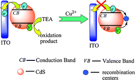
The photocurrent intensity of the QDs greatly decreased in the presence of Cu2+ (Fig. 2). It was reported that the addition of Cu2+ to the CdS solution led to binding of Cu2+ onto the surface of the semiconductor, the rapid reduction of Cu2+ to Cu+ occurred under illumination, and CuxS (x = 1, 2) would also form on the surface of CdS due to the chemical displacement of surface Cd2+ by copper ions resulting from the lower solubility of CuxS (x = 1, 2) than that of CdS.28 The red-shift in absorption spectrum of CdS after the addition of Cu2+ (Fig. S2 in the ESI†) also indicated this binding. The formation of Cu+ or CuxS (x = 1, 2) on the surface of CdS created new energy levels in the bandgap below the conduction band of CdS, which provided a new channel for electron–hole recombination. Due to the electron–hole recombination at these recombination centers (Cu+ or CuxS) on the CdS surface, the photocurrent intensity of CdS QDs decreased in Cu2+ solution. The possible mechanism for the photoelectrochemical detection of Cu2+ is depicted in Scheme 1.
 | ||
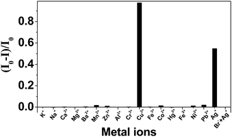
| Fig. 2 Effects of different ions on the photocurrent intensity of ITO/(PDDA/CdS) electrode in 0.1 M PBS (pH 7.0) containing 0.1 M TEA. All the metal ions had concentrations of 2.0 × 10⁻⁵ M. | ||
 | ||
| Scheme 1 The photophysics of CdS QDs in the absense and presence of Cu2+. | ||
The effects of different metal ions (K+, Na+, Cu2+, Mg2+, Ca2+, Ba2+, Co2+, Al3+, Ni2+, Fe3+, Zn2+, Cd2+, Hg2+, Pb2+, and Ag+) with concentration of 2.0 × 10⁻⁵ M on the photocurrent intensities of CdS QDs were investigated. From Fig. 2, we can see that Ag+ could also decrease the photocurrent intensity of CdS QDs besides Cu2+. This can be explained by the formation of Ag2S on the surface of CdS, because the Ksp of Ag2S (−log Ksp = 49.2) is much lower than that of CdS (−log Ksp = 26.2),29 and Ag+ can easily displace Cd2+ on CdS surface.30–32 In the absorption spectrum (see Fig. S3 in the ESI†), the red-shift of CdS QDs after the addition of Ag+ was observed, indicating the formation of Ag2S on the surface of CdS.31 Ag2S formed on the surface of CdS could also act as recombination centres for electrons and holes because of its lower band energy than that of CdS,33 which led to the decrease of photocurrent. It is worth noting that the Ksp of HgS is also lower than that of CdS.34 However, no photocurrent decrease was observed in 2.0 × 10⁻⁵ M Hg2+ solution, indicating that no interaction between CdS and Hg2+ occurred. It may be due to the fact that Hg(II) solution was prepared in HCl to avoid its hydrolysis and existed in the form of [HgClx](x−2)− (x = 3 or 4). The complexation of Hg2+ by Cl− hindered its interaction with CdS QDs. It was also proved by absorption spectrum (see Fig. S4 in the ESI†), in which no spectral shift was observed in the presence of Hg(II) solution.
For Ag+, the decrease of the photocurrent was much lower than that of Cu2+ at the same concentration. Addition of Br− to Ag+ containing solutions resulted in insoluble and undetectable AgBr, which can eliminate the interference of Ag+ without disrupting the photocurrent response of Cu2+. Thus, based on the decrease effect of Cu2+ on the photocurrent intensity of CdS QDs, a highly sensitive and selective photoelectrochemical Cu2+ sensor was developed.
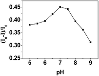
The effect of pH in a range between 5.0 and 9.0 was studied in order to select the optimum conditions for the determination of Cu2+ with CdS QDs. As shown in Fig. 3, the maximum change of photocurrent intensity occurred when the pH was 7.0. For the solutions with lower pH values, H+ could compete with Cu2+ to react with the photogenerated electrons of CdS, because H+ can be reduced to H2 by the photogenerated electrons of CdS nanoparticles.35,36 When the solution pH was above 7.0, the photocurrent responses also decreased. This might be due to the formation of Cu(OH)2 (Ksp = 4.8 × 10⁻²⁰). By calculations using Ksp of Cu(OH)2, for 5.0 × 10⁻⁷ Cu2+, copper-hydroxo precipitation could form when the concentration of H+ was below 3.1 × 10⁻⁷ M. So, 0.1 M TEA in PBS buffer of pH 7.0 was recommended in this work.
 | ||
| Fig. 3 Effect of pH on reaction between Cu2+ and CdS QDs. The concentration of Cu2+ is 5.0 × 10⁻⁷ M. | ||
The effect of copper ions on the photocurrent of CdS QDs is shown in Fig. 4A. The photocurrent intensity of the QDs decreased with the increase of the concentration of Cu2+. A good linear relationship (R = 0.996) was found between the value of the photocurrent decrease (I0 − I)/I0 and the logarithm of the concentration of Cu2+ over the range from 0.02 to 20.0 μM (Fig. 4B), where I0 and I are the photocurrent intensity of CdS QDs in the absence and presence of Cu2+. The detection limit, calculated following the 3σ IUPAC criteria, is 1.0 × 10⁻⁸ M. The standard deviation for five replicate measurements of a solution containing 5.0 × 10⁻⁷ M Cu2+ is 3.8%, indicating a good reproducibility of the method. Compared to the fluorescence method using expensive instruments, this photoeletrochemical method is low cost. It is also simpler than the electrochemical method which usually needs a pre-concentration process.
![(A) Effect of different concentrations of Cu2+ on the photocurrent intensity of ITO/(PDDA/CdS) electrode: (a) 8.0 × 10⁻⁸ M, (b) 5.0 × 10⁻⁷ M, (c) 2.0 × 10⁻⁶ M and (d) 1.0 × 10⁻⁵ M. (B) Plot of photocurrent decrease [(I0 − I)/I0] of CdS QDs versus log [Cu2+].](/image/article/2010/NR/c0nr00084a/c0nr00084a-f4.gif) | ||
| Fig. 4 (A) Effect of different concentrations of Cu2+ on the photocurrent intensity of ITO/(PDDA/CdS) electrode: (a) 8.0 × 10⁻⁸ M, (b) 5.0 × 10⁻⁷ M, (c) 2.0 × 10⁻⁶ M and (d) 1.0 × 10⁻⁵ M. (B) Plot of photocurrent decrease [(I0 − I)/I0] of CdS QDs versus log [Cu2+]. | ||
In summary, TGA capped CdS QDs were used to develop a highly sensitive and selective photoelectrochemical sensor for Cu2+. This work provides the first example of QDs for the photoelectrochemical sensing of metal ion. It is expected that the present study can serve as a foundation to the application of QDs in photoelectrochemical ion sensing and might be easily extended to other ions or molecules sensing by photoelectrochemistry.
This work was supported by the National Natural Science Foundation (No. 20890021), the National Natural Science Funds for Creative Research Groups (20821063) and the 973 Program (2007CB936404) of China.
References
- T. Vo-Dinh, P. Kasili and M. Wabuyele, Nanomed.: Nanotechnol., Biol. Med., 2006, 2, 22–30 CrossRef CAS.
- J. A. Hansen, R. Mukhopadhyay, J. O. Hansen and K. V. Gothelf, J. Am. Chem. Soc., 2006, 128, 3860–3861 CrossRef CAS.
- M. K. Nazeeruddin, D. DiCenso, R. Humphry-Baker and M. Gratzel, Adv. Funct. Mater., 2006, 16, 189–194 CrossRef CAS.
- G. Maduraiveeran and R. Ramaraj, Anal. Chem., 2009, 81, 7552–7560 CrossRef CAS.
- J. Wang, C. Timchalk and Y. H. Lin, Environ. Sci. Technol., 2008, 42, 2688–2693 CrossRef CAS.
- F. Gouanvé, T. Schuster, E. Allard, R. Méallet-Renault and C. Larpent, Adv. Funct. Mater., 2007, 17, 2746–2756 CrossRef CAS.
- C.-Y. Chen, C.-T. Cheng, C.-W. Lai, P.-W. Wu, K.-C. Wu, P.-T. Chou, Y.-H. Chou and H.-T. Chiu, Chem. Commun., 2006, 263–265 RSC.
- P. Wu, Y. Li and X. P. Yan, Anal. Chem., 2009, 81, 6252–6257 CrossRef CAS.
- R. Freeman, T. Finder and I. Willner, Angew. Chem., Int. Ed., 2009, 48, 7818–7821 CrossRef CAS.
- H. Cui, W. Wang, C. F. Duan, Y. P. Dong and J. Z. Guo, Chem.–Eur. J., 2007, 13, 6975–6984 CrossRef CAS.
- X. Liu, H. Jiang, J. P. Lei and H. X. Ju, Anal. Chem., 2007, 79, 8055–8060 CrossRef CAS.
- X. F. Wang, Y. Zhou, J. J. Xu and H. Y. Chen, Adv. Funct. Mater., 2009, 19, 1444–1450 CrossRef CAS.
- D. G. Hafemen, J. W. Parce and M. McConnell, Science, 1988, 240, 1182 CAS.
- A. Ikeda, M. Nakasu, S. Ogasawara, H. Nakanishi, M. Nakamura and J.-i. Kikuchi, Org. Lett., 2009, 11, 1163–1166 CrossRef CAS.
- R. Gill, M. Zayats and I. Willner, Angew. Chem., Int. Ed., 2008, 47, 7602–7625 CrossRef CAS.
- P. Bertoncello and R. J. Forster, Biosens. Bioelectron., 2009, 24, 3191–3200 CrossRef CAS.
- V. Pardo-Yissar, E. Katz, J. Wasserman and I. Willner, J. Am. Chem. Soc., 2003, 125, 622–623 CrossRef CAS.
- H. B. Yildiz, R. Freeman, R. Gill and I. Willner, Anal. Chem., 2008, 80, 2811–2816 CrossRef CAS.
- G.-L. Wang, P.-P. Yu, J.-J. Xu and H.-Y. Chen, J. Phys. Chem. C, 2009, 113, 11142–11148 CrossRef CAS.
- G.-L. Wang, J.-J. Xu, H.-Y. Chen and S.-Z. Fu, Biosens. Bioelectron., 2009, 25, 791–796 CrossRef CAS.
- H. M. Chen, Y. Zheng, L. Xu, J. Xu, K. J. Chen and D. Feng, Superlattices Microstruct., 2000, 27, 1–5 CrossRef CAS.
- W. W. Yu, L. Qu, W. Guo and X. Peng, Chem. Mater., 2003, 15, 2854–2860 CrossRef CAS.
- W. Zhang, Y. R. Shi, L. B. Gan, C. H. Huang, H. X. Luo, D. G. Wu and N. Q. Li, J. Phys. Chem. B, 1999, 103, 675–681 CrossRef CAS.
- R. Gill, F. Patolsky, E. Katz and I. Willner, Angew. Chem., Int. Ed., 2005, 44, 4554–4557 CrossRef CAS.
- A. B. Ellis, S. W. Kaiser and M. S. Wrighton, J. Am. Chem. Soc., 1976, 98, 1635–1637 CrossRef CAS.
- A. B. Ellis, S. W. Kaiser and M. S. Wrighton, J. Am. Chem. Soc., 1976, 98, 6855–6866 CrossRef CAS.
- L. Sheeney-Haj-Ichia, B. Basnar and I. Willner, Angew. Chem., Int. Ed., 2005, 44, 78–83 CrossRef.
- A. Isarov and J. Chrysochoos, Langmuir, 1997, 13, 3142–3149 CrossRef CAS.
- J. R. Goatesm, A. G. Colb, E. L. Gray and N. D. Faux, J. Am. Chem. Soc., 1951, 73, 707–708 CrossRef.
- B. Sadtler, D. O. Demchenko, H. Zheng, S. M. Hughes, M. G. Merkle, U. Dahmen, L. W. Wang and A. P. Alivisatos, J. Am. Chem. Soc., 2009, 131, 5285–5293 CrossRef CAS.
- M. Y. Han, W. Huang, C. H. Chew and L. M. Gan, J. Phys. Chem. B, 1998, 102, 1884–1887 CrossRef CAS.
- M. Ristova, M. Ristov, P. Tosev and M. Mitreski, Thin Solid Films, 1998, 315, 301–304 CrossRef CAS.
- J.-F. Reber and M. Rusek, J. Phys. Chem., 1986, 90, 824–834 CrossRef CAS.
- N. B. Pendyala and K. S. R. Koteswara Rao, Colloids Surf., A, 2009, 339, 43–47 CrossRef CAS.
- T. Hirai, Y. Bando and I. Komasawa, J. Phys. Chem. B, 2002, 106, 8967–8970 CrossRef CAS.
- G. J. Ma, H. J. Yan, J. Y. Shi, X. Zong, Z. B. Lei and C. Li, J. Catal., 2008, 260, 134–140 CrossRef CAS.
Footnote |
| † Electronic supplementary information (ESI) available: experimental procedures for QD synthesis, electrode modification, photoelectro-chemical and absorption spectra. See DOI: 10.1039/c0nr00084a/ |
| This journal is © The Royal Society of Chemistry 2010 |
