Fabrication and growth mechanism of three-dimensional spherical TiO2 architectures consisting of TiO2 nanorods with {110} exposed facets†
Yan
Sang
,
Baoyou
Geng
* and
Jie
Yang
College of Chemistry and Materials Science, Anhui Key Laboratory of Functional Molecular Solids, Anhui Laboratory of Molecular-Based Materials, Anhui Normal University, Wuhu, 241000, P. R. China. E-mail: bygeng@mail.ahnu.edu.cn
First published on 3rd August 2010
Abstract
In this paper, we report on the fabrication of a novel rutile TiO2 architecture consisting of nanorods with {110} exposed facets through a simple hydrothermal method without using any templates. An outside-in ripening mechanism is proposed to account for the formation of the TiO2 architectures.
The formation of the TiO2 architectures can be attributed to the Ostwald step rule and highly acidic medium. Significantly, the current method is suitable for high-yield (>98%) production of the TiO2 architectures with nearly 100% morphological yield. This research provides a facile route to fabricate rutile TiO2 with three-dimensional microstructures based on nanounits. It is easy to realize their industrial-scale synthesis and application because of the simple synthesis method, low cost, and high yield.
1. Introduction
In recent years, scientists have exploited many methods to fabricate all kinds of nanomaterials with different composition, morphology, size and structure. However, with the development of nanotechnology, they found that many properties are determined not only by their composition, morphology and size,1 but also by their shape and exposed facets, which determine surface atomic arrangement and coordination.2As an important semiconductor, TiO2 has been extensively investigated for a vast range of applications, including photocatalysis, solar cells/batteries, hydrogen sensors, and self-cleaning sensors, owing to its peculiar chemical and physical behaviors.3–11 Recently, much research has focused on controlling the exposed facets of TiO2 nanostructures.12 TiO2 is found in three different crystalline phases: anatase, rutile, and brookite. Although less attention has been focused on rutile than anatase TiO2, rutile TiO2, however, has some advantages over anatase such as higher chemical stability, higher refractive index, and cheaper production cost etc.13 Especially, rutile TiO2 (110) has become the most studied oxide surface in surface science, and it is generally used to model TiO2 catalytic properties under ultrahigh vacuum conditions.14 Additionally, previous research has found that partially reduced TiO2 provides an excellent prospect for imaging chemical reactions with atomic resolution using scanning tunneling microscopy.15 For the reduced rutile TiO2 (110) surface, the bridge-bonded oxygen (BBO) vacancies are the most common point defects. For this reason, rutile TiO2 (110) has been widely used as a substrate for organic catalysis. For example, Hu and co-workers studied the O2 supply pathway in CO oxidation on Au/TiO2 (110). They found that there is a charge transfer from TiO2 in the presence of OH to O2, and the O2 adsorption energy depends linearly on the O2 charge.16 Li et al. studied the correlation between bonding geometry and band gap states at organic–inorganic interfaces based on rutile TiO2 (110).17 They also investigated the intrinsic hydrogen diffusion on BBO rows of TiO2 (110).18 And many other studies based on TiO2 (110) have been performed.19 However, the previously used TiO2 (110) is the bulk material; nanostructural TiO2 (110) should provide a significant improvement on its properties.
In addition, previous investigations indicated that the properties of nanostructures could be tailored not only by controlling the size and phase of the structures, but also by adjusting their morphology. To improve their properties, various morphologies of TiO2 nanostructures, including porous particles, fibers, tubes and spheres, have been prepared by means of chemical or physical methods.4–9 Moreover, three-dimensional (3D) micro/nanoarchitectures have stimulated much attention since such architectures combine the features of micrometer- and nanometer-scaled building blocks and show unique properties different from those of the 1D structures.20 Especially, the preparation of highly oriented rodlike crystals has been proposed as a method to increase the effective surface area of TiO2 nanostructures, which would allow for improving their performance.4,21 Micro- and nanostructures with highly oriented rodlike crystals have attracted significant interest owing to their many attractive characteristics, such as economical use of materials and high surface area to volume ratios. As is well known, there are few reports on oriented aggregation of single-crystalline rutile TiO2 nanorods into 3D architectures in high yield by a one-step reaction in solution. Considering the applications of rutile TiO2 in the field of surface science and the chemical industry associated with its high refractive index, the controlled fabrication of 3D TiO2 architectures with determined phase and structure is very significant.
Here, we report a facile hydrothermal route to fabricate uniform TiO2 architectures in high yields. The as-obtained products are 3D spherical architectures consisting of single-crystal TiO2 nanorods with {110} exposed facets. The current method is suitable for high-yield (>98%) production of TiO2 nanostructures with nearly 100% morphological yield. Significantly, the special morphology of the products gives a good chance to improve the performance of the TiO2 structures. And it is easy to realize their industrial-scale synthesis and application because of the simple synthetic method, low cost, and high yield.
2. Experimental section
All chemicals were of analytical grade and used as received without further purification. Titanium tetrachloride (TiCl4) and concentrated nitric acid (HNO3) were supplied by the Shanghai Chemical Reagent Company.The one-step hydrothermal preparation of the TiO2 nanostructures was performed as follows. Typically, an aqueous solution of TiCl4 (4 mL, 3 M) was added slowly into 18 mL of concentrated nitric acid (60%) under vigorous stirring and a white precipitate was formed. After the mixture was stirred for 5 min, the precipitate dissolved and the resulting solution was added to a 30 mL Teflon-lined autoclave, and the hydrothermal synthesis was conducted at 160 °C for 10 h in an electric oven. After the reaction was completed, the autoclave was allowed to cool to room temperature, and the resulting solid products were collected by means of centrifugation, washed with deionized water and absolute ethanol several times, and then dried in vacuum at 70 °C for 12 h.
The composition of the products was characterized by means of powder X-ray diffraction (XRD) by using a XRD-6000 (Japan) X-ray diffractometer with Cu-Kα radiation (λ = 1.54060 Å) at a scanning rate of 0.05° s−1. The morphologies were observed by using scanning electron microscopy (SEM) micrographs, which were taken using a Hitachi S-4800 scanning electron microscope. Transmission electron microscopy (TEM) and high-resolution transmission electron microscopy (HRTEM) were performed using JEM 2010 F microscopes.
3. Results and discussion
Fig. 1(a)–(c) exhibits SEM images with different magnifications of TiO2 products after reaction for 10 h at 160 °C. Fig. 1(a) shows that the products consist of large quantities of spherical or broken spherical architectures. The products are clean and with a diameter range of 2 to 3.5 μm. The high-magnification SEM image in Fig. 1(b) reveals that the obtained products are three-dimensional architectures, which have a solid core on which grow large quantities of short radially oriented nanorods. It is noted that all the constituent nanorods are aligned and radially oriented with their growth axes perpendicular to the surface of the spheres without any substrate support. The surface SEM image of the architecture (Fig. 1(c)) indicates that the nanorods are arranged compactly on the surface of the spherical architectures with diameters of about 20–30 nm, which is estimated from the high-magnification SEM image in the inset of Fig. 1(c). The corresponding XRD pattern in Fig. 1(d) reveals that all the diffraction peaks of the products are in good agreement with a rutile phase TiO2 (JCPDS file no. 89-4920).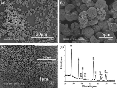 | ||
| Fig. 1 (a)–(c) SEM images with different magnifications of TiO2 three-dimensional architectures obtained after reaction at 160 °C for 10 h. Inset in (c) is the corresponding high-magnification SEM image of (c). (d) The corresponding XRD pattern of the obtained TiO2 products. | ||
The TEM image in Fig. 2(a) shows that the obtained structures are spherical architectures with a coarse surface. A high-magnification TEM image of the region marked by a rectangle in Fig. 2(a) is displayed as Fig. 2(b). The image clearly reveals that the surface of the sphere is constructed by radial nanorods arrays from the center to the surface of the sphere and the diameters of the constituent nanorods are about 20–30 nm, which is consistent with observations from the SEM images.
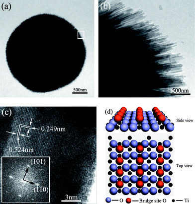 | ||
| Fig. 2 (a), (b) and (c) Transmission electron microscopy (TEM) images. The inset in (c) shows the selected area electron diffraction (SAED) pattern of a TiO2 nanorod obtained after reaction at 160 °C for 10 h. (d) The schematic model of TiO2 (110). | ||
A HRTEM image of an individual TiO2 nanorod is shown in Fig. 2(c), which reveals its highly crystalline nature. The measured interplanar distances of 0.324 nm and 0.249 nm correspond to the (110) and (101) planes of a rutile TiO2 crystal, respectively. The high crystallinity of the TiO2 nanorods can be further inferred from the corresponding Fourier transform electron diffraction pattern of the HRTEM (inset in Fig. 2(c)), which is consistent with the rutile structure of TiO2 with diffraction spots due to (110) and (101) planes. Fig. 2(d) shows a schematic model of the TiO2 (110) plane. The corresponding energy-dispersive X-ray spectroscopy (EDS) result (Fig. S1†) indicates that the nanorods mainly consist of Ti and O with an approximate atomic ratio of 1![[thin space (1/6-em)]](https://www.rsc.org/images/entities/char_2009.gif) :
:![[thin space (1/6-em)]](https://www.rsc.org/images/entities/char_2009.gif) 1.96, which is nearly consistent with the stoichiometry of TiO2. The Cu peak comes from the copper mesh used for TEM.
1.96, which is nearly consistent with the stoichiometry of TiO2. The Cu peak comes from the copper mesh used for TEM.
For a better understanding of the growth mechanism of the TiO2 nanostructures, temperature- and time-dependent morphology evolution studies were conducted. The temperature-dependent morphology evolution of the products is shown in Fig. 3.
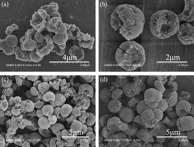 | ||
| Fig. 3 Typical SEM images of the temperature-dependent TiO2 three-dimensional architectures: (a) 80 °C; (b) 120 °C; (c) 160 °C and (d) 200 °C. The products were obtained after a reaction time of 10 h. | ||
Fig. 3 shows SEM images of the temperature-dependent morphology evolution process after reaction at 80, 120, 160 and 200 °C for 10 h while keeping other conditions unchanged. From Fig. 3(a), we find that the products at 80 °C consist of irregular particles with diameters of about 1–1.5 μm. The surfaces of the particles are coarse and careful observation may find that there are many rod-like particles on the surface of the products, which may be considered as the initial state of the nanorods. Fig. 3(b) clearly shows that the products obtained at 120 °C have quasi-spherical shapes with diameters of about 2 μm. The outside of the products are obviously composed of short nanorods. But the morphologies of the products were not very perfect. When the reaction temperature is 160 °C, the SEM image in Fig. 3(c) reveals that the obtained products consist of spherical or broken spherical particles with diameters of about 2–3 μm. The surfaces of the particles are covered with a layer of nanorods, which take on uniform morphology and the figurations of the particles are very fine. When the reaction is performed at 200 °C, more spherical particles are broken and the sizes of the TiO2 three-dimensional architectures increases (Fig. 3(d)). The length of the TiO2 nanorods on the surface of the particles increases with the reaction temperature.
The time-dependent morphology evolution of the products is shown in Fig. 4 (we selected the products obtained at 200 °C with different reaction time). Because the nucleation process in a hydrothermal system is rapid, we can only observe the aging process of the products. Fig. 4(a) shows the SEM image of the obtained products after reaction for 2 h at 200 °C, which illustrates that after 2 h aging the products are irregular particles with diameters of about 1 μm. The higher-magnification SEM (inset) shows that there are some spots on the surface of the particles. Fig. 4(b) shows that the products obtained after reaction for 5 h at 200 °C consist of spherical architectures with diameters of about 2 μm. The corresponding higher-magnification SEM image (inset in Fig. 4(b)) clearly shows that the obtained architecture has a solid core on which grow large quantities of short nanorods with diameters of about 20 nm and lengths less than 500 nm. When the reaction time was prolonged to 10 h, the surface morphology of the products did not change remarkably (Fig. 4(c)). However, the inset in Fig. 4(c) clearly shows that the size of the solid core becomes smaller than that of the products after 5 h reaction time. Meanwhile, the nanorods on the surface of the solid core became longer (about 800 nm) and the diameter of the TiO2 nanorods increased (40–60 nm). Fig. 4(d) shows the SEM images of the products obtained after a reaction time of 20 h, which clearly reveals that the surface of the TiO2 three-dimensional architectures is looser than those of the products obtained with shorter reaction times. In addition, the sizes of the TiO2 spherical architectures are further increased. Comparing the fine morphology of the architectures with the products obtained above, the inset in Fig. 4(d) reveals that the solid core of the TiO2 spherical architectures nearly disappears after reaction for 20 h. Moreover, the lengths of the TiO2 nanorods are found to increase noticeably to 1 μm or longer and the diameters to increase to about 100 nm. The temperature- and time-dependent morphology evolution demonstrates that reaction time and temperature directly affect the final morphology of the products, especially the size of the TiO2 spherical architectures and the length of the TiO2 nanorods; both of them are increased with the reaction time and temperature.
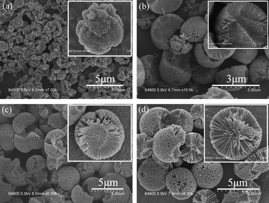 | ||
| Fig. 4 Time-dependent SEM images of the products (obtained at 200 °C) with different magnifications: (a) 2 h; (b) 5 h; (c) 10 h and (d) 20 h. | ||
On the basis of all the above observations, a plausible mechanism was proposed to illustrate the growth of TiO2 nanostructures (as shown in Scheme 1).
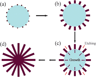 | ||
| Scheme 1 Schematic illustration of the proposed growth mechanism of the TiO2 nanostructures. (a) Formation of TiO2 particles at the early stages of the reaction; (b) aging process of the TiO2 particles; (c) continuous aging and concentrated nitric acid etching process; (d) the solid particles are subject to outside-in ripening and form 3D TiO2 architectures. | ||
During the early stages, the nucleation process happens in a hydrothermal system and the formed nuclei aggregate together to decrease the surface energy. The crystallinity of the solid aggregations is low because of the short reaction time and the formed particles are fractional noncrystals with many small crystals embedded amongst them (Scheme 1(a)). From the point of view of crystal growth, the formation of many small crystals is kinetically favored, (i.e. they nucleate more easily) but large crystals are thermodynamically favored. Thus, from a standpoint of kinetics, it is easier to nucleate many small crystals. However, small crystals have a larger surface area to volume ratio than large crystals. Molecules on the surface are energetically less stable than the ones already well ordered and packed in the interior. Large crystals, with their greater volume to surface area ratio, represent a lower energy state. Thus, many small crystals will attain a lower energy state if transformed into large crystals (Ostwald ripening) (Scheme 1(b)). Theoretically, as the active points, the small crystals will enlarge in all directions. However, in our case, the formed TiO2 particles are located in the surroundings of concentrated nitric acid, which will etch the surface of the TiO2 particles slowly. The noncrystal parts of the particles are easily etched while the crystal parts can remain stable and grow continuously larger. Therefore, the etching action will hinder growth along the tangential direction and the growth of the small crystals will be mainly along the radial direction (Scheme 1(c)). With prolonged hydrothermal treatment, these solid particles are subject to outside-in ripening and formation of the TiO2 architectures (Scheme 1(d)). The XRD patterns of products obtained at different temperatures are given in the supporting information (Fig. S2†), which show the crystallinity increasing with the increase in reaction temperature. A similar situation can also be observed with the reaction time. Time-dependent XRD patterns are shown in Fig. S3.† Ribeiro et al. have demonstrated that anatase TiO2 is the preferential crystalline phase formed at short treatment times, as expected according to the Ostwald step rule.22 Increasing the treatment time, the volume of the rutile phase is increased in detriment to the anatase phase. Our products are obtained with reaction times of more than 2 h, which is enough to perform the phase transformation from anatase to rutile. The corresponding XRD patterns of the products are indexed to rutile TiO2.
In order to demonstrate the effect of the nitric acid on the final products, we investigated the effect of nitric acid concentration on the morphology. Fig. 5 shows the SEM images of the products using different concentrations of nitric acid. At a lower concentration of nitric acid, the obtained products are quasi spheres (Fig. 5(a)). The high-magnification SEM image in the inset of Fig. 5(a) shows that the surface of the spheres is compact with some protuberances. The surface of the products obtained at a higher concentration of nitric acid is obviously rougher than that of the former (Fig. 5(b)). The high-magnification SEM in the inset of Fig. 5(b) further exhibits the incompact surface for the sphere and the rod-like morphology can be clearly observed. The results prove the etching effect of nitric acid in the growth process. In addition, many studies have proven that the pH value plays a substantial role in the formation, structure, and crystal morphology of TiO2.23–26 Wu and co-workers reported that the phase transformation from anatase to rutile occurs simultaneously with particle growth in a highly acidic medium.27 In our case, the hydrothermal progress takes place in a highly acidic medium and thus results in the formation of rutile TiO2.
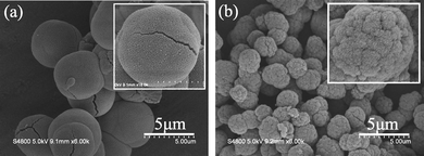 | ||
| Fig. 5 SEM images of the products after reaction at 160 °C for 10 h, with nitric acid concentrations of (a) 30% and (b) 50%. | ||
4. Conclusions
In summary, we have developed a simple method for the synthesis of TiO2 nanostructures consisting of single-crystal TiO2 nanorods with {110} exposed facets. The length of the TiO2 nanorods can be adjusted through reaction temperature and time. A novel outside-in ripening mechanism is proposed to account for the formation of these TiO2 architectures. This research should provide a facile route to fabricate 3D rutile TiO2 architectures. It is easy to realize their industrial-scale synthesis and application because of the simple synthetic method, low cost, and high yield.Acknowledgements
This work was supported by the National Natural Science Foundation of China (20671003, 20971003), the Key Project of Chinese Ministry of Education (209060), Science and Technological Fund of Anhui Province for Outstanding Youth (10040606Y32), the Education Department of Anhui Province (2006KJ006TD) and the Program for Innovative Research Team in Anhui Normal University.References
- (a) J. Zhang, K. Sasaki, E. Sutter and R. R. Adzic, Science, 2007, 315, 220 CrossRef CAS; (b) V. R. Stamenkovic, Science, 2007, 315, 493 CrossRef CAS.
- (a) R. Narayanan and M. A. El-Sayed, Nano Lett., 2004, 4, 1343 CrossRef CAS; (b) H. Lee, S. E. Habas, S. Kweskin, D. Butcher, G. A. Somorjai and P. D. Yang, Angew. Chem., Int. Ed., 2006, 45, 7824 CrossRef CAS; (c) N. Tian, Z. Y. Zhou, S. G. Sun, Y. Ding and Z. L. Wang, Science, 2007, 316, 732 CrossRef CAS; (d) B. Y. Geng, C. H. Fang, F. M. Zhan and N. Yu, Small, 2008, 4, 1337 CrossRef CAS; (e) X. G. Han, M. S. Jin, S. F. Xie, Q. Kuang, Z. Y. Jiang, Y. Q. Jiang, Z. X. Xie and L. S. Zheng, Angew. Chem., Int. Ed., 2009, 48, 9180 CrossRef CAS; (f) Z. Y. Zhou, Z. Z. Huang, D. Chen, J. Q. Wang, N. Tian and S. G. Sun, Angew. Chem. Int. Ed., 2010, 49, 411 CAS.
- Q. Zheng, B. X. Zhou, J. Bai, L. H. Li, Z. J. Jin, J. L. Zhang, J. H. Li, Y. B. Liu, W. M. Cai and X. Y. Zhu, Adv. Mater., 2008, 20, 1044 CrossRef CAS.
- X. D. Wang, C. J. Summers and Z. L. Wang, Adv. Mater., 2004, 16, 1215 CrossRef CAS.
- C. X. Ji and P. C. Searson, J. Phys. Chem. B, 2003, 107, 4494 CrossRef CAS.
- F. Li, J. He, W. L. Zhou and J. B. Wiley, J. Am. Chem. Soc., 2003, 125, 16166 CrossRef CAS.
- D. G. Shchukin and R. A. Caruso, Chem. Mater., 2004, 16, 2287 CrossRef CAS.
- J. Jiang and A. Kucernak, Chem. Mater., 2004, 16, 1362 CrossRef CAS.
- K. Suzuki, K. Ikari and H. Imai, J. Am. Chem. Soc., 2004, 126, 462 CrossRef CAS.
- E. Hosono, S. B. Fujihara, K. Kakiuchi and H. Imai, J. Am. Chem. Soc., 2004, 126(25), 7790 CrossRef CAS.
- E. Hosono, S. B. Fujihara, H. Imai, I. Honma, I. Masaki and H. S. Zhou, ACS Nano, 2007, 1(4), 273 CrossRef.
- (a) A. Vittadini, A. Selloni, F. P. Rotzinger and M. Grätzel, Phys. Rev. Lett., 1998, 81, 2954 CrossRef CAS; (b) X. Q. Gong and A. Selloni, J. Phys. Chem. B, 2005, 109, 19560 CrossRef CAS; (c) X. Q. Gong, A. Selloni, M. Batzill and U. Diebold, Nat. Mater., 2006, 5, 665 CrossRef CAS; (d) C. W. Peng, T. Y. Ke, L. Brohan, M. R. Plouet, J. C. Huang, E. Puzenat, H. T. Chiu and C. Y. Lee, Chem. Mater., 2008, 20, 2426 CrossRef CAS; (e) Y. Q. Dai, C. M. Cobley, J. Zeng, Y. M. Sun and Y. N. Xia, Nano Lett., 2009, 9, 2455 CrossRef CAS.
- (a) N. G. Park, J. Lagemaat and A. J. Frank, J. Phys. Chem. B, 2000, 104, 8989 CrossRef CAS; (b) K. J. Kim, K. D. Benksten, J. Lagemaat and A. J. Frank, Chem. Mater., 2002, 14, 1042 CrossRef CAS.
- (a) Z. R. Zhang, O. Bondarchuk, J. M. White, B. D. Kay and Z. Dohnálek, J. Am. Chem. Soc., 2006, 128, 4198 CrossRef CAS; (b) M. A. Henderson, Surf. Sci. Rep., 2002, 46, 1 CrossRef CAS; (c) O. Bondarchuk, Y. K. Kim, J. M. White, J. Kim, B. D. Kay and Z. Dohnálek, J. Phys. Chem. C, 2007, 111, 11059 CrossRef CAS; (d) Z. Dohnálek, J. Kim, O. Bondarchuk, J. M. White and B. D. Kay, J. Phys. Chem. B, 2006, 110, 6229 CrossRef CAS.
- (a) S. Suzuki, K. Fukui, H. Onishi and Y. Iwasawa, Phys. Rev. Lett., 2000, 84, 2156 CrossRef CAS; (b) R. Schaub, R. Thostrup, N. Lopez, E. Laegsgaard, I. Stensgaard, J. K. Norskov and F. Besenbacher, Phys. Rev. Lett., 2001, 87, 266104 CrossRef CAS; (c) I. M. Brookes, C. A. Muryn and G. Thornton, Phys. Rev. Lett., 2001, 87, 266103 CrossRef CAS; (d) O. Bikondoa, C. L. Pang, R. Ithnin, C. A. Muryn, H. Onishi and G. Thornton, Nat. Mater., 2006, 5, 189 CrossRef CAS.
- L. M. Liu, B. McAllister, H. Q. Ye and P. Hu, J. Am. Chem. Soc., 2006, 128, 4017 CrossRef CAS.
- S. C. Li, J. G. Wang, P. Jacobson, X. Q. Gong, A. Selloni and U. Diebold, J. Am. Chem. Soc., 2009, 131, 980 CrossRef CAS.
- S. C. Li, Z. R. Zhang, D. Sheppard, B. D. Kay, J. M. White, Y. G. Du, I. Lyubinetsky, G. Henkelman and Z. Dohnálek, J. Am. Chem. Soc., 2008, 130, 9080 CrossRef CAS.
- (a) L. Gamble, M. B. Hugenschmidt, C. T. Campbell, T. A. Jurgens and J. W. Rogers, J. Am. Chem. Soc., 1993, 115, 12096 CrossRef CAS; (b) Y. K. Kim, R. Rousseau, B. D. Kay, J. M. White and Z. Dohnálek, J. Am. Chem. Soc., 2008, 130, 5059 CrossRef CAS; (c) Z. R. Zhang, R. Rousseau, J. L. Gong, B. D. Kay and Z. Dohnálek, J. Am. Chem. Soc., 2009, 131, 17926 CrossRef CAS.
- F. Lu, W. P. Cai and Y. G. Zhang, Adv. Funct. Mater., 2008, 18, 1047 CrossRef CAS.
- A. Fujishima, T. N. Rao and D. A. Tryk, J. Photochem. Photobiol., C, 2000, 1, 1 CrossRef CAS.
- C. Ribeiro, C. Vila, D. B. Stroppa, V. R. Mastelaro, J. Bettini, E. Longo and E. R. Leite, J. Phys. Chem. C, 2007, 111, 5871 CrossRef CAS.
- C. C. Wang and J. Y. Ying, Chem. Mater., 1999, 11, 3113 CrossRef CAS.
- M. M. Wu, J. M. Long, A. H. Huang, Y. J. Luo, S. H. Feng and R. R. Xu, Langmuir, 1999, 15, 8822 CrossRef CAS.
- F. Izumi and Y. Fujiki, Bull. Chem. Soc. Jpn., 1976, 49, 709 CAS.
- F. Izumi, Bull. Chem. Soc. Jpn., 1978, 51, 1771.
- M. M. Wu, G. Lin, D. H. Chen, G. G. Wang, D. He, S. H. Feng and R. R. Xu, Chem. Mater., 2002, 14, 1974 CrossRef CAS.
Footnote |
| † Electronic supplementary information (ESI) available: EDS pattern of TiO2 products (Fig. S1) and XRD patterns of products obtained after reaction at different temperatures (Fig. S2) or for different times (Fig. S3). See DOI: 10.1039/c0nr00151a |
| This journal is © The Royal Society of Chemistry 2010 |
