In vitro hydrogen production—using energy from the sun
Henning
Krassen
*a,
Sascha
Ott
a and
Joachim
Heberle
b
aDepartment of Photochemistry and Molecular Science, Uppsala University, Box 523, SE-751 20 Uppsala, Sweden. E-mail: henning@krassen.de; Fax: +46 18-471-6844; Tel: +46 18-471-6582
bFreie Universität, Department of Physics, D-14195 Berlin, Germany. E-mail: jheberle@zedat.fu-berlin.de; Fax: +49 30-838-56510; Tel: +49 30-838-53337
First published on 23rd November 2010
Abstract
Using solar energy to produce molecular hydrogen is a promising way to supply the civilization with clean energy. Nature provides the key components to collect solar energy as well as to reduce protons, scientists have developed mimics of these enzymatic centers and also found new ways to catalyze the same reactions. This perspective article surveys the different components and in particular the various coupling possibilities of a light sensitizer and catalyst. Pros and cons are discussed.
 Henning Krassen | Henning Krassen studied biochemistry at Bielefeld University (Germany). He finished his studies with his diploma thesis in biophysical chemistry “Single Cell Electroporation” in 2006. After receiving his diploma, he did his PhD in the group of Joachim Heberle (2009). Focus of his thesis was “Biomimetic Hydrogen Production” as a light-driven sustainable energy source. After his PhD, he moved to the group of Stenbjörn Styring in Uppsala (Sweden) to investigate a newly discovered cyanobacterial photosystem I (2009). |
 Sascha Ott | Sascha Ott was born in Heilbronn, Germany in 1973. He received a Bachelor of Science (Hons) from the Flinders University of South Australia (Adelaide, Australia), and a PhD from University College London (UK) in 2002. After a postdoc with Björn Akermark and Licheng Sun at Stockholm University (Sweden), he moved to Uppsala University where he is currently associate professor, funded by the Swedish Research Council. His research interests are focused on synthesis and evaluation of functional H2ase active site models and the incorporation of phosphorus heteroatoms into oligoacetylenic frameworks. |
 Joachim Heberle | Joachim Heberle studied chemistry at the Universities of Stuttgart and Würzburg (Germany). After receiving his Diploma in Physical Chemistry from Würzburg University (1988), he moved to the Free University of Berlin to do his PhD in Biophysics (1991). His postdoc work at the Hahn-Meitner-Institute in Berlin led him to build an independent research group for Biomolecular Spectroscopy at the Research Centre Jülich (1993). After his Habilitation at Düsseldorf University (1998), he became Full Professor in Biophysical Chemistry at Bielefeld University (2005). Recently, he moved to Freie Universität Berlin to join the Faculty of Physics as a Full Professor in Experimental Molecular Biophysics (2009). |
1. Introduction
Mankind needs an increasing supply of energy. If we consider to stop using fossil fuels as main energy source—either due to climate reasons or due to limited supply and increasing costs—new possibilities to make usable energy available need to be developed. Because our need for energy is not only a need for electricity, but mainly a need for fuel, we must produce the latter from primary energy sources in order to avoid severe environmental problems.1Our sun is the largest and longest-lasting primary energy source. Derived from the solar constant of the earth (1.366 kW m−2), the solar energy that hits our planet exceeds our global energy demand by four orders of magnitude even when a rise of up to 33 TW is expected by 2050.2,3
Many energy carriers, like hydrogen, methanol, or ethanol, can be produced from solar energy. In terms of the CO2 balance, these fuels are all CO2-neutral as the amount of released greenhouse gas upon burning the fuel is the same as the amount consumed for its production. A major advantage of hydrogen is that it can be used with virtually zero harmful emissions and, thus, local pollution hot spots can be avoided. Without impairing the relevance of the other energy carriers, we will focus here on hydrogen production from solar energy, which is discussed as an ideal way for sustainable energy production.4,5
In this perspective article, we discuss possibilities on how to use sunlight for the production of molecular hydrogen. We focus on systems which directly or indirectly connect a light sensitizer to a hydrogen-producing catalyst excluding, however, cellular systems which are beyond the scope of this paper.
When a system for light-driven hydrogen production is constructed, three essential components are required: (1) the light sensitizer is necessary to absorb photons, make electrons available on an elevated energetic level, and by this provide the reductive driving force for H2 formation. Electrons for the sensitizer maybe supplied from another catalytic center, directly from a sacrificial donor, or from an electrode. (2) A catalyst must be used, which uses the reductive force to produce molecular hydrogen. Protons from autoprotolysis of water can be envisaged as a substrate. (3) The wire must allow the electron transfer between sensitizer and catalyst. This includes electron flow through the wire as well as electron transfer between sensitizer and catalyst by tunneling. In the latter case, the wire is used to control the distance and to keep the electron transfer rate sufficiently fast. Fig. 1 summarizes the discussed components and wires.
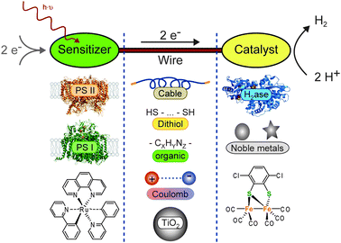 | ||
| Fig. 1 Systems for light-driven hydrogen production can be described as a construction kit including various sensitizers and catalysts, which can be linked through different wires. The basic principle and (some) possible components are shown: (left column, sensitizers) photosystem II (PS II, PDB-ID: 1S5L), photosystem I (PS I, PDB-ID: 1JB0), Ru(bpy)3; (central column, wires) solid cable, dithiol, organic, Coulomb interaction, TiO2 particle; (right column, catalysts) hydrogenase (H2ase, PDB-ID: 1FEH), noble metal particles (nanoparticles as circles, colloidals as star), Fe2 complex. | ||
In addition to the functional differentiation, the components are distinguished by their origin: on the one hand, nature provides a large number of enzymes, which qualify as sensitizers (e.g.photosystems I and II) or catalysts (different hydrogenases). Other redox active proteins or amino acid chains can be used as wires and be produced in the native system. On the other hand, (in-)organic synthesis allows us to create sensitizers, catalysts, and wires. Some very promising approaches are inspired by the native systems. Possible combinations and their advantages and disadvantages for future applications are discussed in the text.
2. Sensitizers
2.1 Photosynthesis
Using light, water is split into molecular oxygen, protons, and electrons. The central part of the light reaction of photosynthesis is conducted by two large protein complexes, namely photosystem I (PS I) and photosystem II (PS II).The primary photosynthetic reaction is initiated by light excitation of the so-called “special-pair” of chlorophyll a molecules (P680) in PS II. A series of electron transfer steps leads to charge separation and the electron is transferred towards PS I viaplastoquinone, cytochrome b6f, and plastocyanin. P680+ is a strong oxidant and retracts an electron from water, which is bound to the manganese cluster, to “refill” the electron hole.
A similar reaction takes place in PS I. Photons are absorbed by a pair of chlorophylls (P700). Intramolecular electron transfer leads to charge separation which results in an even stronger reductive force than in PS II. The redox potentials of the iron–sulfur clusters FA and FB, which form the acceptor site of PS I, have been determined to be −0.54 and −0.59 V (vs.SHE), respectively.6 In nature, this reductive force is used to reduce the electron carrier ferredoxin. But in principle any suitable electron acceptor, which is close to FA/FB, can be reduced and re-direct the electrons towards hydrogen production.
Discussing photosynthesis, it should be mentioned that it is not only an electron transfer process, but also the creation of a proton gradient across the thylakoid membrane. The oxygen evolving cluster of PS II releases protons on the luminal side and plastoquinone takes up protons from the stromal side and releases them on the luminal side. The gradient is used afterwards by the ATP-synthase to make the energy available as chemical energy.
2.2 What makes a sensitizer “efficient”?
From functional perspective, PS I and PS II are photosensitizers in which the photo-excited state is quenched by a series of electron transfer steps to afford a final charge-separated state that can be used to donate electrons. We derive the basic principle of light sensitizers: “Light absorption must result in charge separation.”Systems which do much useful work per quantity of energy are commonly called “efficient”. A long lifetime of the charge-separated state is the key characteristic of efficient sensitizers as the strong reductive force disappears with charge recombination. Two approaches are used to decrease the probability of charge recombination: (1) the electron is transferred to a remote redox-active group with fast kinetics. (2) The electron hole is refilled from another electron donor. Typically, a sacrificial donor D (e.g.amines, EDTA, ascorbate) is used, which is sufficiently easily oxidized to render the process thermodynamically feasible and preclude back electron transfer by rapid degradation or re-reduction of D+. Alternatively, electrons are directly provided by an efficiently coupled cathode.
From an economical point of view, an ideal sensitizer that converts solar radiation into chemical energy without any losses will not be applied on a large scale if its stability is too low and its production costs are too high. Economic calculations are beyond the scope of this paper, but the relevance of the electron source shall be addressed. Sacrificial donors have to be produced beforehand and the used energy impairs the overall energy balance. Thus, a cheap and abundant electron donor is required. Water fulfills the requirements of high and cheap availability and seems to be the obvious choice. PS II, for example, is able to oxidize water which allows for the sustainable conversion of solar energy. An alternative could be ethanol or methanol from fermentation processes. In laboratory scale experiments used donors are generally tertiary amines such as triethanolamine, triethylamine, or EDTA. Ascorbate and acetate have also been used.
Another important characteristic of the sensitizer is the spectral range in which absorption leads to a productive reaction. This range should match the solar spectrum as good as possible to make the sensitizer efficient.
Any system, which collects light to oxidize water and which reduces protons to molecular hydrogen, can be used in a “perfect cycle”. Hydrogen is consumed in a fuel cell with water as the only product—forming a cycle of water which converts solar radiation into electrical energy (see Fig. 2).
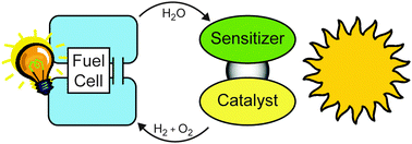 | ||
| Fig. 2 A perfect cycle of water which converts solar radiation into electrical energy. | ||
2.3 In vitro application of PS I and PS II
The first step is to immobilize the protein on the electrode surface. Gold electrodes can be modified with heterobifunctional molecules, which bind to the surface via a thiol-group and expose a second functional group to the bulk. A Ni-NTA (nitrilotriacetic acid)-terminated surface allows binding of any His-tagged protein, modification with streptavidin yields an affinity for Strep-tagged proteins, and exposed lysine residues may bind terminal aldehydic groups of surface modifiers.7–9 The chemical structure of a Ni-NTA-terminated surface with a bound His-tag is shown in Fig. 3B. In addition, it is an option to introduce cysteine residues into the sequence which can bind directly to a bare gold electrode.10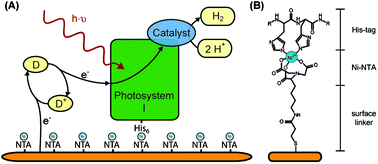 | ||
| Fig. 3 (A) Schematic view of photosystem I immobilized on a chemically-modified solid electrode. Electrons are provided to the photosystem by a soluble electron donor (D). The oxidized form (D+) diffuses to the surface and is electrochemically re-reduced. In this example, the electrons are directly transferred to the catalyst, which is bound to photosystem I, where protons are reduced to molecular hydrogen. (B) Chemical structure of the Ni-NTA-terminated surface with the His-tag of the protein ligating the Ni2+. | ||
Photosystems I and II have previously been used in electrochemical setups to convert light energy into electrical energy.10,11 Yet, to our knowledge, direct electron transfer between photosystem I or II and a solid electrode has not been achieved so far. Soluble electron carriers are used to bridge the gap between protein and electrode. Fig. 3A depicts the electron transfer around immobilized PS I. The electrons can either be used by a tethered catalyst or transferred to the counter electrode (via a soluble carrier).
In order to compare different catalytic surfaces the activity is commonly normalized to the number of reaction centers or the surface area. Here, it is important to distinguish between two different surface areas: (1) the real surface area is the exposed surface area and takes all hills and valleys into account. (2) The geometrical surface is macroscopically measured and only equals the real surface area for an atomically flat surface.
Optimization approaches in this field aim at increasing the surface area, i.e. a higher real surface area per geometrical surface area and, thus, a higher concentration of photosensitizers per geometrical area. Terasaki et al. increase the real surface area by a factor of 26 by sedimentation of gold nano particles on a planar gold substrate and the photocurrent of immobilized PS I increases from 290 nA cm−2 to 1600 nA cm−2 (per geometrical surface area).12 Ciesielski et al. prepare nanoporous gold electrodes by dealloying silver from a gold/silver leaf. The real surface area increases (5–12-fold) and the PS I photocurrent is enhanced by a factor of 3 to 6.9Chemical deposition of gold on a silicon surface is another way to increase the real surface area and yields surfaces with a surface roughness of approximately 2.5.13
All of the previous approaches were performed on protein monolayers. However, the surface concentration of active sensitizers is also increased when embedded in a redox-active hydrogel. The photocurrent from PS II was increased by a factor of ∼10 in a hydrogel, as compared to PS II monolayers.11,14 These optimization approaches are schematically summarized in Fig. 4.
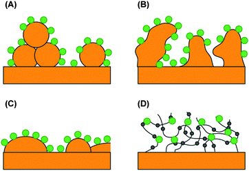 | ||
| Fig. 4 Electrodes with an increased number of catalytic centers per geometrical surface area. The large dots represent immobilized photosynthetic centers on (A) the gold nanoparticle electrode, (B) the nanoporous gold leaf electrode, (C) the gold island film electrode, and (D) the redox hydrogel electrode. The small dots are embedded, redox-active Os(bipy)2Cl groups. | ||
2.4 Drawback—the stability of isolated proteins
Photoinhibition occurs in all oxygen evolving photosynthetic organisms and the main targets and self-repair mechanisms have been intensively investigated, particularly for PS II.15When purified protein is employed in an in vitro device, the cellular self-repair machinery is typically not present. Thus, photodamages to the sensitizer are no longer repaired. In the absence of the cellular protein factory, damaged protein is not replaced by freshly synthetized proteins. Some surfaces offer the option to desorb the sensitizers (e.g. desorb protein that was bound viaNi-NTA–His-Tag interaction by imidazole) and regenerate the surface by binding fresh sensitizers. Since each individual operation adds up to the total costs and renders the sensitizer less economical, the aim must be to drastically increase the stability of isolated proteins to avoid frequent replacement, once these systems are used in large-scale applications. Stability and efficiency have to compensate the costs for protein isolation and surface modification.
An important step towards increased stability is to mimic the native environment. For the membrane protein PS I, the stability in the detergent-solubilized form (as isolated) is compared to the stability when the protein is embedded in a lipid bilayer. We immobilized the recombinant PS I fused to a hydrogenase catalyst on a gold surface and detected the photocurrent as a measure of the activity of the protein.16Fig. 5 depicts the decrease of the photocurrent with time. After 1 h of illumination the photocurrent of detergent-stabilized PS I drops to 20% of the initial value, while 40% of the activity is retained for the fusion construct stabilized by the lipid bilayer.
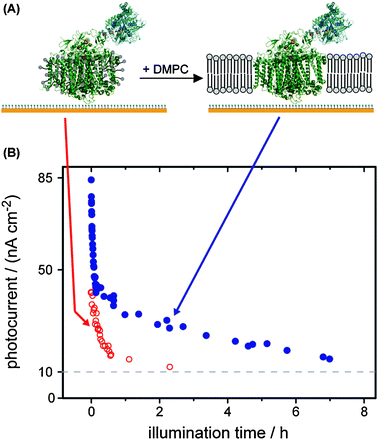 | ||
| Fig. 5 (A) A fusion protein of PS I and a hydrogenase catalyst is immobilized on a modified gold electrode.16 Upon addition of dimyristoyl-phosphatidylcholine (DMPC) and slowly removing the detergent a lipid bilayer forms around PS I. (B) The photocurrents of detergent-stabilized (as isolated) PS I (open circles) and lipid bilayer-stabilized PS I (full circle) are plotted versus illumination time. | ||
As a major step towards the application of such a device, a high level of activity was recently reported for platinized PS I during >2000 hours of operation.17
2.5 Synthetic sensitizers
While nature uses two photosystems, the exposition of synthetic sensitizers is vast and literally hundreds of potential catalysts could be considered. Apart from obvious factors like synthetic feasibility and thermodynamic and photolytic stability, other functional factors need to be considered when choosing a sensitizer. These are: (1) light absorption should occur in the visible region, not in the UV or near IR. (2) Excited state lifetime should be sufficiently long to allow for electron transfer to an acceptor site and ultimately to a catalytic unit. (3) The light-induced state of the sensitizer needs to have sufficient driving force to allow for electron transfer at an appreciable rate.The primary charge separated state in PS I results from a set of chlorophylls. Synthetic mimics of these structural units have fascinated chemists for centuries and exist in the form of porphyrinoids, i.e.porphyrins, phthalocyanines and corroles, that absorb light in the same green region of the visible spectrum as PS I. Advantages of porphyrinoids are their synthetic versatility and the fact that they often contain non-toxic and cheap metal centers or are even metal-free. Disadvantages with these sensitizers lie in the general low yields in their preparation and the general low lifetime of their high energy singlet excited states.
Since 1970, (poly-)pyridine complexes of transition metals, in particular, those of heavier elements like Ru, Os, Re, Ir have been in the center of interest. Their photophysics has been studied in great detail and is often characterized by high energy excited states with long lifetimes and light absorption over large parts of the visible spectrum. While most of these properties can be tuned by varying the metal and an appropriate ligand set, a major problem with these systems is that they employ heavy rare metals.
2.6 Synthetic sensitizers mimicking PS II
The mechanism of the catalytic process of PS II is very intricate as four oxidation equivalents have to be accumulated within the confined space of a few atoms to afford water oxidation. Nature has thus developed a highly complex machinery, the so-called oxygen evolving complex (OEC) consisting of four manganese and one calcium cations. The electrostatic repulsion that would be caused by a buildup of electron holes is counter-balanced by charge compensation reactions through deprotonation and ligand rearrangements.Synthetic molecular systems, that are true mimics of PS II and are able to perform the photo-sensitized oxidation of water, are still scarce. Light-induced hole transfer events from a Ru-based sensitizer to a manganese complex were reported already in 1997,18 but a complete water-oxidizing system based on such a Ru–Mnxassembly is still elusive. A major difficulty in supramolecular homogenous catalysis is that such systems are often prone to oxidative degradation that limits complex stability and turnover numbers. The catalytic units in multi component arrays that are currently explored consist of IrO2,19Co3O4,20 or even CaMn2O421nanoparticles. Structurally more defined inorganic coordination compounds, which contain organic ligands, often employ noble metals such as Ru22 or Ir.23
In an approach that avoids the use of organic ligands, Hill and co-workers have developed all-inorganic polyoxometallates as ligands to ruthenium and could show that such a construct is able to photocatalytically oxidize water with high turnover numbers.24 Most recently, also a polyoxometallate ligated to more abundant cobalt has been shown to be a catalyst for water oxidation.25 With these advances, it's a question of time when functional light-driven systems that show appreciable turnover numbers and that are based on abundant earth metals will be reported.
3. Catalysts
3.1 Criteria for “good” catalysts
Similar to sensitizers, the catalyst must be stable as long as possible to be economically feasible. Furthermore, the activity of the catalyst should be high to make use of all electrons provided by the sensitizer. Moreover, the produced hydrogen should not inhibit the catalyst, in order to maintain a constantly high hydrogen evolution rate.Many catalysts for proton reduction are (more or less irreversibly) inhibited by oxygen. A higher oxygen tolerance will result in a higher long-term stability and will make the catalyst cheaper to handle, because the requirements for the anaerobic environment are lower. It is also an advantage if the inhibition by oxygen is reversible, because an anaerobic environment could be avoided for purification/synthesis.
Another important parameter of the catalyst is its overpotential for proton reduction. A higher (more positive) overpotential means that we need more energy to produce a molecule of hydrogen. If we can lower the overpotential, the potential gap between sensitizer and catalyst becomes larger, and, thus, the driving force for electron transfer increases.
3.2 Noble metal catalysts
The best overpotentials among homogenous metal catalysts are found for noble metals, in particular palladium, platinum, rhodium.26,27But the noble metals are too expensive and too rare to supply the world with the necessary amount of proton reduction catalyst. We need a catalyst which is based on a cheaper, more abundant metal and provides similar or better activity, overpotential, and stability.
3.3 Hydrogenases
Nature has solved the problem to use iron (and nickel) for the production of highly efficient H2 evolving catalyst—a family of enzymes called hydrogenases. In the metabolic pathway, hydrogenases are alternative electron acceptors instead of oxygen, and they are likely to have evolved in a pre-photosynthetic, reducing atmosphere.28 Hydrogenases have been discovered in 1930 and at the present time heterologous and recombinant expression, as well as in vitro maturation systems are established.29,30Two classes of proton-reducing hydrogenase enzymes are distinguished here: (1) [FeFe]-hydrogenases, which overall have the highest hydrogen evolution rates up to 9000 mol H2 s−1 mol hydrogenase−1, but suffer from high oxygen sensitivity.31–33 (2) [NiFe]-hydrogenases have a lower hydrogen evolution activity, but they are active in O2-containing atmosphere or the inhibition by oxygen is at least reversible.32,34,35
For future application it is important to identify or produce the best catalyst. The catalytic mechanisms and the inhibition by oxygen are under investigation and might allow us to produce a highly active and oxygen-tolerant hydrogenase.36,37 But besides the question of activity and stability, we also have to consider how a hydrogenase can be connected to the different sensitizers. So far little is known about the characteristics of the electron transfer pathway in hydrogenases and their impact on sensitizer–catalyst systems.
3.4 In vitro application of hydrogenases
The biological catalyst hydrogenase can be immobilized on an appropriate electrode and reduces the overpotential to a value close to zero. Hydrogen can be produced at a higher potential (= lower energy) than on a platinum electrode. This has been demonstrated for a variety of hydrogenase enzymes including the [NiFe]-hydrogenases of Ralstonia species and [FeFe]-hydrogenases of Desulfovibrio desulfuricans and Clostridium acetobutylicum on graphite electrodes.34,38,39 The turnover number of [NiFe]-hydrogenases are comparable with Pt catalysts.40While affinity to graphite electrodes seems a conserved property of hydrogenases, the binding to gold electrodes has to be mediated by heterobifunctional linker molecules. But the use of a gold surface allows the application of surface-enhanced infrared spectroscopy (SEIRAS) and surface plasmon resonance (SPR) while studying electrochemistry—as shown for the [FeFe]-hydrogenase CrHydA1 of Chlamydomonas reinhardtii on a carboxy-terminated gold electrode.41 The use of SPR allows us to determine the surface coverage and the number of catalytic centers. In this study the surface activity was 1% of the activity in solution and the soluble electron carrier methyl viologen was necessary to achieve activity. Nonetheless, with further optimization of the immobilization protocol and progress from the methodical side, it seems possible to monitor changes of the catalytic center (i.e. the IR signature of the CO and CN− ligands) time-resolved during an electrochemical experiment and understand the immobilized enzyme.
3.5 First synthetic H2-producing photocatalytic systems
First reports of multi-component systems which were capable to catalyze the light-driven reduction of water appeared as early as in the late 1970s. In perhaps the most prominent example [Ru(bpy)3]2+ is employed as the photosensitizer.42–44 Once excited by the absorption of a photon, *[Ru(bpy)3]2+ is capable of reducing methyl viologen which functions as an electron mediator (eqn (1)). The reduced methyl viologen radical cation can now react with water on the surface of a platinum dioxide catalyst to form hydrogen and thereby regenerate its (oxidized) dicationic form (eqn (2)). The catalytic cycle is closed and the photosensitizer regenerated after reduction of the photo-oxidized ruthenium complex by triethanol amine (TEOA), which acts as a sacrificial electron donor (eqn (3)).| *[Ru(bpy)3]2+ + MV2+ → [Ru(bpy)3]3+ + MV+˙ | (1) |
 | (2) |
| TEOA + [Ru(bpy)3]3+ → TEOA+ + [Ru(bpy)3]2+ | (3) |
3.5 Bio-inspired NiFe compounds
The heterometallic character of the [NiFe] hydrogenase active site makes the preparation of close structural models a great challenge. Since the X-ray structure determination of the enzymes, a number of more or less close structural mimics have been reported.47 The current state-of-the-art is a model of the CO-inhibited form of the enzyme's active site (Fig. 6A and B).48 Although some closer mimics of the [NiFe]-hydrogenase active site have been reported to show H2-evolution activity in electrochemical assays, the systems usually suffer from high overpotentials, low turnover numbers and rapid decompositions.![(A) Active site of [NiFe]-hydrogenases in the CO-inhibited state. The four cysteine (S–Cys) ligands connect the cluster to the protein scaffold. (B) Selected biomimetic model complex of the [NiFe]-active site.48 tBu abbreviates the tert-butyl substituent. (C) H-cluster of [FeFe]-hydrogenases. (D) Example for a biomimetic model of the H-cluster. SR denotes a tripodal chelating ligand.51](/image/article/2011/CP/c0cp01163k/c0cp01163k-f6.gif) | ||
| Fig. 6 (A) Active site of [NiFe]-hydrogenases in the CO-inhibited state. The four cysteine (S–Cys) ligands connect the cluster to the protein scaffold. (B) Selected biomimetic model complex of the [NiFe]-active site.48 tBu abbreviates the tert-butyl substituent. (C) H-cluster of [FeFe]-hydrogenases. (D) Example for a biomimetic model of the H-cluster. SR denotes a tripodal chelating ligand.51 | ||
In contrast, mononuclear Ni complexes that are coordinated by bidendate bis-phosphane ligands which contain nitrogen bases can catalyze the reduction of proton and the oxidation of hydrogen close to the thermodynamic potential.49 These Ni complexes, developed by DuBois and co-workers, have recently been immobilized on a carbon nanotube and could be shown to be catalysts for the electrochemical reduction of protons at an overpotential of 20 mV and achieve turnover rates as high as 100.000 per Ni complex.50
3.6 Bio-inspired Fe2 compounds
First model complexes of the [FeFe]-hydrogenase active site were reported in the late 90s—shortly after the first structure elucidation of the enzyme by X-ray crystallography. Milestones in the modelling community are the synthesis of the complete H-cluster (Fig. 6C) that consists of 6 Fe and 6 S centers, and the realization of structures with bridging CO and terminal hydride ligands.51 From a functional viewpoint, first biomimetic homogenous catalysts for electrochemical proton reduction were reported at the start of this millennium.52,53 Since then, the field has literally exploded with more than 250 catalysts and catalyst candidates having been reported until 2009.54 One example is shown in Fig. 6D. Almost all catalyze the electrochemical reduction of protons although none of them as fast and at similarly mild potential as the enzymes.In analogy to the charge compensation reactions discussed for the PS II mimics, the reduction potential of a [FeFe]-complex and its basicity are inter-connected. Reduction of the complex will increase its basicity and the reactivity of the hydride intermediates towards protons. In turn, initial protonation will lead to a decrease of the potential required for reduction. Complexes with strong donor ligands (cyanides, phosphines) are initially harder to reduce but can be protonated prior to reduction, at least with stronger proton donors. On the other hand, complexes without particular donor ligands or complexes, that contain even electron-withdrawing ligands are reduced at a mild potential, can however only be protonated after initial reduction. The sequence of reduction and protonation events in the catalytic cycle thus strongly depends on the ligand set of the [FeFe]-site, the proton activity of the medium, and the available reduction potential. Alterations of the latter two can lead to a situation where the same complex may engage in different catalytic cycles.55,56
3.7 Other synthetic systems
Synthetic molecular catalysts for the reduction of protons are developed also outside structural biomimicry.57 Apart from numerous reports that are based on precious and noble metals, such as Pt, Pd, Rh or Re, macrocycle-stabilized cobalt complexes are frequently encountered. Electrocatalytic hydrogen evolution was reported for cobalt complexes with a BF2-bridged diglyoxime or tetraimine ligands.584. “Wires”—coupling of sensitizer and catalyst
We distinguish two basic strategies for the coupling process. Indirect coupling describes systems where the electrons are transferred between the catalyst and sensitizer either via an electrode system or by diffusion of a soluble electron carrier (Fig. 7A and B). Direct coupled systems comprise all other possibilities—i.e. hybrid complexes of sensitizer and catalyst in solution or on electrodes. Possible coupling concepts are illustrated in Fig. 7C and D.4.1 Indirect coupling
The simplest example for a “sensitizer–wire–catalyst” system, which we can imagine, is a photovoltaic anode, which is connected to a bare platinum cathode. The photovoltaic half cell provides electrons, which are conducted through a normal cable and used to reduce protons at the platinum surface.Different photoanodes and catalytic cathodes can replace the different half cells and provide a large number of possible combinations. The fundamental requirement for the single half cells is efficient electron transfer between electrode and sensitizer or catalyst, respectively. For the indirect coupling it is necessary that the half cell potential of the sensitizer half cell is lower (more negative) than the one of the catalyst half cell—in order to move electrons towards the catalyst.
Separation of catalyst and sensitizer is both advantage and disadvantage. The separation allows us to use the optimal environment (buffer, pH,…) for both components without the need for a compromise. For example, a low pH can be used for the catalyst to provide high concentrations of the substrate H+ and the pH for the sensitizer can be optimized for its stability at the same time. It is also easily possible to couple a chosen catalyst with different sensitizers in order to adjust the system to different regional conditions, like average light intensity. And if high stability is achieved for one component, it can remain untouched when the other component is replaced/regenerated.
A disadvantage is that the electron transfer between sensitizer and catalyst is at least divided into two steps—transfer from sensitizer to electrode and from electrode to catalyst (illustrated in Fig. 7A). Thus, the driving force, which is given by the potential difference, is lower for each individual step.
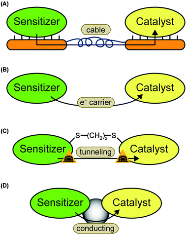 | ||
| Fig. 7 Possible electron transfer pathways: (A) sensitizer and catalyst are immobilized on different electrodes. The electrons are indirectly transferred via the electrode system. (B) The sensitizer transfers one or more electrons to a soluble carrier. The carrier diffuses towards the catalysts and provides the electron(s) for proton reduction. This is the second way of indirect electron transfer. (C) A molecular wire is used to bring the electron donor site of the sensitizer close to the electron acceptor site of the catalyst. The electrons can tunnel directly. The case of a dithiol linker is chosen as an example. Another option are one-component systems where the wire is part of the molecule. (D) Sensitizer and catalyst are connected by a molecular wire which mediates the electron transfer. | ||
The second option for indirect coupling is the use of a soluble energy carrier (Fig. 7B). In these systems the sensitizer and catalyst must be located in the same compartment and, thus, be able to work in the same environment. The redox potential must be located between the ones of the electron donor site of the sensitizer and the electron acceptor site of the catalyst. For example ferredoxin and methyl viologen are both able to transfer electrons between PS I and some hydrogenases.16,41
4.2 Direct coupling
Among protein sensitizers, PS I has been in the focus of research for some years. The potentials of the terminal iron–sulfur clusters FA and FB (−0.54 V and −0.59 V) are sufficiently negative to transfer electrons to a catalyst and drive hydrogen production. In addition, they are located close to the protein surface and can be accessed for different coupling techniques, as described in the next chapters.4.3 Platinized PS I
Ferredoxin, the native electron acceptor of PS I, binds to a positively charged area located in the subunit PsaD on the stromal close to the terminal iron–sulfur cluster FB. It has been demonstrated that this area can be chemically modified with colloidal platinum particles. [PtCl6]2− can be used as the Hill oxidant and accept four electrons consecutively from PS I at the reducing site of PS I.59 Another possibility is photoprecipitation. Platinization has been shown for PS I in thylakoid membranes and isolated PS I, as depicted in Fig. 8A and B. Rates up to 5.5 μmol H2 mg Chl−1 h−1 were reported with Cyt c6 as an electron donor.17 Similar experiments with [OsCl6]2− have shown light-driven hydrogen production as well at significant lower rate.59,60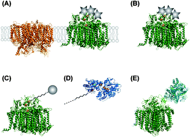 | ||
| Fig. 8 Different coupled systems between PS I and proton reducing catalysts. Metal nanoparticles are illustrated as grey circles, colloid particles as grey stars. (A) Thylakoid membranes are modified by precipitation of metallocatalysts (platinum or osmium). PS II (left) is included as an example for other membrane proteins within the thylakoid membrane. (B) Isolated PS I is metallized by precipitation of Pt or Os. (C) Au or Pt nanoparticles are connected to the terminal FB cluster of PS I by a molecular wire (e.g.1,6-hexanedithiol). For the sake of clarity, the molecular wire is not scaled to the same dimension as the proteins. (D) Molecular wires are also used to connect PS I to the distal cluster of hydrogenases. (E) A hydrogenase is genetically fused to the PsaE subunit of PS I. | ||
Using “wire” as a very elastic term, the Coulomb interactions are the one in this system. The catalyst comes close enough to the FB cluster to accept electrons via tunneling (Fig. 8C) and use them for proton reduction.
4.4 PS I–molecular wire–noble metal
Pioneering work to specifically bind gold and platinum nano particles to PS I have been performed by the lab of Golbeck (Fig. 7C).The native cysteine ligand on the solvent exposed position of FB in the PS I subunit PsaC was mutated into a cysteine. This apo-enzyme was then in vitro reconstituted with mercaptoethanol-stabilized [4Fe–4S] clusters. Mercaptoethanol can be replaced by dithiol molecules which allow binding of noble metal nano particles via the second sulfhydryl group (see Fig. 8C).61 Different molecular wires have been used to optimize the hydrogen production rate. Very short molecular wires resulted in low rates, either by inefficient coupling or by their inability to shield the protein from denaturation by the metal surface. Aliphatic wires longer than six C atoms resulted in lower rates, while aromatic wires resulted in higher rates.62,63
4.5 PS I–molecular wire–hydrogenase
The same technique as described before can be used to couple PS I to hydrogenase enzymes (see Fig. 8D), if the coordination sphere of the distal iron–sulfur cluster of the hydrogenase is prepared by a similar Cys → Gly mutation.63Another approach is to directly fuse PS I and hydrogenase to each other. The PS I subunit PsaE is genetically attached to a hydrogenase which can assemble with the PsaE-deletion mutant of PS I (see Fig. 8E). For in vitro studies, the deletion mutant of PS I is immobilized on a chemically modified gold electrodevia His-tag–Ni-NTA interaction. The surface is then incubated with a solution of the PsaE–hydrogenase fusion protein, which assembles the complete hybrid complex. The advantage of this system is that all components can be produced within the cell. This coupling is promising to direct electrons towards hydrogen production instead of competing pathways like NADP+ reduction and, thus, increase cellular hydrogen production.16,64
4.6 Ru(bpy)3–TiO2–hydrogenase
TiO2 forms semiconducting particles which can act as a wire between sensitizers and catalysts which are immobilized on the particle's surface (see Fig. 7D and Fig. 8D).The sensitizer [RuII(bpy)2(4,4′-(PO3H2)2-bpy)] binds to the TiIV sites of the surface via its phosphonic acid groups. And it has been shown that some hydrogenases spontaneously attach to the TiO2 surface. Upon excitation by visible light in the presence of an artificial electron donor an electron is transferred from the Ru-sensitizer via the conducting band of the TiO2 particle to the distal cluster of the hydrogenase.65 Activities up to 14.2 μmol H2 h−1 cm−2 have been reported.66
4.7 Sensitizer—artificial catalyst
Provided that the electronics for electron transfer from the light-induced high-energy state at the sensitizer to the catalytic site is adequately chosen,55 all catalysts that have been discussed in Section 3 can be combined with suitable sensitizers to drive the light driven reduction of protons.67The currently reported proton reduction schemes can mainly be divided into two classes: (1) multi component schemes where the sensitizer encounters the catalytic moiety in a diffusion controlled reaction and (2) discrete dyads where the two functional units are connected through a covalent or supramolecular bond.
An advantage of the former approach lies in the possibility to screen many potential catalyst candidates without the need of elaborate synthetic efforts. Furthermore, the bimolecular system offers the possibility to alter the sensitizer-to-catalyst ratio since a rise of the sensitizer concentration may for instance be advantageous in cases where the availability of reducing equivalents is limiting.68 The advantage of covalently linked systems is that the kinetics of the electron transfer steps can be fine-tuned by careful choice and implementation of the bridging unit. Control of electron transfer kinetics is crucial in biological electron transfer reactions and may also prove superior in synthetic artificial systems despite severe synthesis challenges.69,70
Apart from reports that utilize noble metal-based catalysts, the most prominent reports of homogenous multi-component systems are based on cobaloxime and diiron catalysts. Lehn and co-workers used cobaloximes as early as in 1983 together with [Ru(bpy)3]2+ as the sensitizer and triethanolamine as the sacrificial electron donor for the light-driven reduction of protons.71 Recently, this multi-component system has been revisited and cobaloxime-based catalysts have now been reported to photocatalytically produce hydrogen when combined not only with a noble metal-based PS, but remarkably also with organic dyes.72 It is worthwhile noting that this report is the first of its kind that reports photocatalytic proton reduction without the need of any noble metals as the sensitizer or in the catalyst. Multi-component systems that employ model complexes of the [FeFe]-hydrogenase active site in conjunction with ruthenium73 or iridium74 based sensitizers have recently been shown to produce H2 with 100s of turnovers (Fig. 9A). Interesting to note that a turnover number in the same order of magnitude has recently been reported for relatively simple Fe0n(CO)m (n = 1–3; m = 5, 9, 12) catalyst in combination with an iridium sensitizer.75
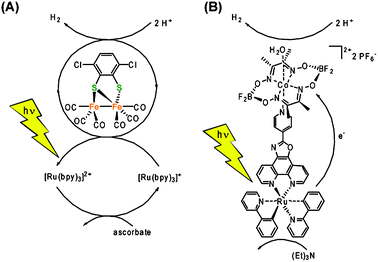 | ||
| Fig. 9 (A) Multi component system utilizing an Fe2 complex as the catalyst and Ru(bpy)3 as the sensitizer.73 (B) A Ru–cobaloxime dyad as an example of a linked sensitizer–catalyst system using supramolecular interactions.80 | ||
Over the last five years, numerous supramolecular or covalently linked dyads for the light-driven reduction of protons have been reported. Ru–Pt76 and Ru–Pd77 based dyads are typical examples of molecular systems that are based on noble metal catalysts. Molecular dyads comprised of a photo sensitizer and a catalyst moiety that is inspired by the [FeFe]-hydrogenase's active site have been reported.55 Early works focused on the covalent linking of the potential [FeFe]-catalyst to a sensitizer through an often unsaturated organic linker.78 Unfortunately, the elaborate dyads did not show the desired function due to a number of reasons. A paper using an appealing supramolecular approach showed a few turnovers of light driven H2 evolution. The most elegant approach to-date was recently reported by Pickett and co-workers, who fabricated a nanophotocathode consisting of InP nanocrystals that are coated with biomimetic [FeFe]-catalysts and immobilized on a gold substrate.79 The aforementioned cobalt glyoximes performed much better in supramolecular schemes with turnovers over 100 being reported (Fig. 9B).80
In summary, it has to be stated that despite the relatively large number and variety of photocatalytic systems that have been investigated, none achieves turnover numbers that are above 10.000.
5. Comparing hydrogen production rates
All reported hydrogen production rates obviously tell how much hydrogen is produced in a defined time interval by a hydrogen producing unit, either by a number of reaction centers or a defined surface area. But still a comparison on-first-view easily leads to wrong conclusions, because the rates are measured under different experimental conditions and different approaches are used to normalize the rates.5.1 Example: hydrogen production using PS I
The best comparison can be made among experiments performed in the same laboratory. Golbeck and coworkers used different aliphatic and aromatic molecular wires to connect platinum nano particles to PS I and measured rates between 2.5 and 312 μmol H2 mg Chl−1 h−1. Using the same coupling method, they connected the [FeFe]-hydrogenase from C. acetobutylicum to PS I and yielded a rate of 3.9 μmol H2 mg Chl−1 h−1. These rates can be compared straight ahead and we can conclude which linker is the most efficient and that the hydrogenase is not perfectly coupled yet.Iwuchukwu et al. reported a rate of ∼5.5 μmol H2 mg Chl−1 h−1 for platinized PS I. Instead of the PS I from spinach they used PS I from Thermosynechococcus elongatus, which has a significant lower chlorophyll content. If we would normalize the rates to the number of reaction centers the hydrogen production rate of systems with spinach PS I would be 3-times increased—compared to the normalization on chlorophyll. In addition the T. elongatusPS I allows operation at higher temperature. Thus, we are comparing optimal rates, but if we think about application it might be more important to compare the rates at RT—in order to minimize heating costs.
In a previous publication, we reported a hydrogen evolution rate of 3 mmol H2 mg Chl−1 h−1 for the fusion protein of PS I and [NiFe]-hydrogenase from Ralstonia eutropha. The chlorophyll content is similar to T. elongatus, and, thus, the rate is still 3-times higher than the one of the best PS I–molecular wire–Pt nanoparticle system, if we normalize the rate per reaction center. Still the comparison is not ideal, the latter rate is normalized to the number of assembled PS I–hydrogenase centers, while the former ones take all PS I centers into account—whether or not coupled to a catalyst.16,63,64
5.2 Different ways to define stability
There is no established, standard way to describe stability. The PS I–molecular wire–hydrogenase constructs from the Golbeck laboratory showed more or less constant activity when stored for greater than 2 months at room temperature under anoxic conditions, Iwuchukwu et al. reported a high level of hydrogen production over more than 2.000 h of illumination and we have shown the fast comparable fast decay of the hydrogen production activity of the fusion protein in Fig. 5. For the synthetic compounds the turn-over-number, the total number of produced hydrogen molecules per catalyst, is commonly measured.All values give important information, we want to know (1) how long we can store a sensitizer–catalyst system before the activity decreases significantly, (2) how much hydrogen can be produced by the system before we have to replace it, (3) and how much time the hydrogen production needs.
A billion turnovers at a rate of 1 H2 year−1 would be as useless as 100 turnovers which happen in a millisecond.
6. Perspective
Many different approaches have succeeded to utilize solar radiation for hydrogen production. Synthetic systems based on non-noble metals promise to be sufficiently cheap to be used for large-scale hydrogen production—given that the rate and turn-over-number will increase drastically in the future. A first example that is beyond the above mentioned two classes is a hybrid nanostructure–molecular catalyst that functions as a nanophotocathode for H2 production.79In vitro systems with isolated proteins will not be the solution to the world's energy and climate problem. The isolation of proteins is too expensive and we don't see the slightest chance to build a power plant based on isolated proteins which works economically. But cellular systems are promising for the future.70Cyanobacteria and green algae perform oxygenic photosynthesis and are able to release some of their excess energy in the form of molecular hydrogen.81–83 We believe that in vitro systems will play an important role to improve cellular hydrogen production. The efficiency of the sensitizer–catalyst coupling can be optimized in vitro and the influence of competitive electron acceptors can be investigated.
No energy source will be “the” solution. It will depend on the local environment which sensitizers and catalysts are promising to combine to stand the economical comparison to other renewable energy sources. Nonetheless, light-driven-hydrogen production can be used to make fuel available from sunlight without going the long way round via electricity.
Interesting sidetrack of this research is that the sensitizers may also be used to provide the driving force for other catalytic processes and the catalysts could be used to translate electric energy into chemical energy, e.g. to smooth out the temporal fluctuations of renewable energies (wind or solar).
Notes and references
- H. B. Gray, Nat. Chem., 2009, 1, 7 CrossRef CAS.
- D. Crommelynck and S. Dewitte, Sol. Phys., 1997, 173, 177–191 CrossRef.
- M. Wang, Y. Na, M. Gorlov and L. C. Sun, Dalton Trans., 2009, 6458–6467 RSC.
- N. Armaroli and V. Balzani, Angew. Chem., Int. Ed., 2007, 46, 52–66 CrossRef CAS.
- R. Eisenberg and D. G. Nocera, Inorg. Chem., 2005, 44, 6799–6801 CrossRef CAS.
- M. C. W. Evans and P. Heathcote, Biochim. Biophys. Acta, 1980, 590, 89–96 CAS.
- K. Ataka, F. Giess, W. Knoll, R. Naumann, S. Haber-Pohlmeier, B. Richter and J. Heberle, J. Am. Chem. Soc., 2004, 126, 16199–16206 CrossRef CAS.
- X. Jiang, A. Zuber, J. Heberle and K. Ataka, Phys. Chem. Chem. Phys., 2008, 10, 6381–6387 RSC.
- P. N. Ciesielski, A. M. Scott, C. J. Faulkner, B. J. Berron, D. E. Cliffel and G. K. Jennings, ACS Nano, 2008, 2, 2465–2472 CrossRef CAS.
- I. Carmeli, L. Frolov, C. Carmeli and S. Richter, J. Am. Chem. Soc., 2007, 129, 12352–12353 CrossRef CAS.
- A. Badura, B. Esper, K. Ataka, C. Grunwald, C. Woll, J. Kuhlmann, J. Heberle and M. Rogner, Photochem. Photobiol., 2006, 82, 1385–1390 CrossRef CAS.
- N. Terasaki, N. Yamamoto, T. Hiraga, I. Sato, Y. Inoue and S. Yamada, Thin Solid Films, 2006, 499, 153–156 CrossRef CAS.
- H. Miyake, S. Ye and M. Osawa, Electrochem. Commun., 2002, 4, 973–977 CrossRef CAS.
- A. Badura, D. Guschin, B. Esper, T. Kothe, S. Neugebauer, W. Schuhmann and M. Rogner, Electroanalysis, 2008, 20, 1043–1047 CrossRef CAS.
- N. Adir, H. Zer, S. Shochat and I. Ohad, Photosynth. Res., 2003, 76, 343–370 CrossRef CAS.
- H. Krassen, A. Schwarze, B. Friedrich, K. Ataka, O. Lenz and J. Heberle, ACS Nano, 2009, 3, 4055–4061 CrossRef CAS.
- I. J. Iwuchukwu, M. Vaughn, N. Myers, H. O'Neill, P. Frymier and B. D. Bruce, Nat. Nanotechnol., 2010, 5, 73–79 CrossRef CAS.
- A. Magnusson, H. Berglund, P. Korell, L. Hammarström, B. Åkermark, S. Styring and L. Sun, J. Am. Chem. Soc., 1997, 119, 10720–10725 CrossRef CAS.
- W. J. Youngblood, S.-H. A. Lee, Y. Kobayashi, E. A. Hernandez-Pagan, P. G. Hoertz, T. A. Moore, A. L. Moore, D. Gust and T. E. Mallouk, J. Am. Chem. Soc., 2009, 131, 926–927 CrossRef CAS.
- F. Jiao and H. Frei, Angew. Chem., Int. Ed., 2009, 48, 1841–1844 CrossRef CAS.
- M. M. Najafpour, T. Ehrenberg, M. Wiechen and P. Kurz, Angew. Chem., Int. Ed., 2010, 49, 2233–2237 CrossRef CAS.
- L. Duan, A. Fischer, Y. Xu and L. Sun, J. Am. Chem. Soc., 2009, 131, 10397–10399 CrossRef CAS.
- J. F. Hull, D. Balcells, J. D. Blakemore, C. D. Incarvito, O. Eisenstein, G. W. Brudvig and R. H. Crabtree, J. Am. Chem. Soc., 2009, 131, 8730–8731 CrossRef CAS.
- Y. V. Geletii, Z. Huang, Y. Hou, D. G. Musaev, T. Lian and C. L. Hill, J. Am. Chem. Soc., 2009, 131, 7522–7523 CrossRef CAS.
- Q. Yin, J. M. Tan, C. Besson, Y. V. Geletii, D. G. Musaev, A. E. Kuznetsov, Z. Luo, K. I. Hardcastle and C. L. Hill, Science, 2010, 328, 342–345 CrossRef CAS.
- J. M. Lehn and J. P. Sauvage, Nouv. J. Chim., 1977, 1, 449–451 Search PubMed.
- N. Toshima, M. Kuriyama, Y. Yamada and H. Hirai, Chem. Lett., 1981, 793–796 CAS.
- K. A. Vincent, A. Parkin and F. A. Armstrong, Chem. Rev., 2007, 107, 4366–4413 CrossRef CAS.
- M. Stephenson and L. H. Stickland, Biochem. J., 1931, 25, 205–214 CAS.
- C. M. English, C. Eckert, K. Brown, M. Seibert and P. W. King, Dalton Trans., 2009, 9970–9978 RSC.
- M. Frey, ChemBioChem, 2002, 3, 153–160 CrossRef CAS.
- R. Cammack, M. Frey and R. Robson, Hydrogen as a Fuel: Learning from Nature, Routledge, UK, 2001, pp. 201–230 Search PubMed.
- M. W. W. Adams, Biochim. Biophys. Acta, 1990, 1020, 115–145 CAS.
- G. Goldet, A. F. Wait, J. A. Cracknell, K. A. Vincent, M. Ludwig, O. Lenz, B. Friedrich and F. A. Armstrong, J. Am. Chem. Soc., 2008, 130, 11106–11113 CrossRef CAS.
- S. P. Albracht, Biochim. Biophys. Acta, 1994, 1188, 167–204 CAS.
- S. T. Stripp, G. Goldet, C. Brandmayr, O. Sanganas, K. A. Vincent, M. Haumann, F. A. Armstrong and T. Happe, Proc. Natl. Acad. Sci. U. S. A., 2009, 106, 17331–17336 CrossRef CAS.
- H. Ogata, W. Lubitz and Y. Higuchi, Dalton Trans., 2009, 7577–7587 RSC.
- K. A. Vincent, A. Parkin, O. Lenz, S. P. J. Albracht, J. C. Fontecilla-Camps, R. Cammack, B. Friedrich and F. A. Armstrong, J. Am. Chem. Soc., 2005, 127, 18179–18189 CrossRef CAS.
- C. Baffert, M. Demuez, L. Cournac, B. Burlat, B. Guigliarelli, P. Bertrand, L. Girbal and C. Leger, Angew. Chem., Int. Ed., 2008, 47, 2052–2054 CrossRef CAS.
- A. K. Jones, E. Sillery, S. P. J. Albracht and F. A. Armstrong, Chem. Commun., 2002, 866–867 RSC.
- H. Krassen, S. Stripp, G. von Abendroth, K. Ataka, T. Happe and J. Heberle, J. Biotechnol., 2009, 142, 3–9 CrossRef CAS.
- J.-M. Lehn and J.-P. Sauvage, Nouv. J. Chim., 1977, 1, 449–451 Search PubMed.
- K. Kalyanasundaram, J. Kiwi and M. Grätzel, Helv. Chim. Acta, 1978, 61, 2720–2730 CrossRef CAS.
- A. Moradpour, E. Amouyal, P. Keller and H. Kagan, Nouv. J. Chim., 1978, 2, 547–549 Search PubMed.
- A. Harriman and M. A. West, Photogeneration of Hydrogen, Academic Press, New York, 1982 Search PubMed.
- E. Amouyal, Sol. Energy Mater. Sol. Cells, 1995, 38, 249–276 CrossRef CAS.
- C. Tard and C. J. Pickett, Chem. Rev., 2009, 109, 2245–2274 CrossRef CAS.
- Y. Ohki, K. Yasumura, M. Ando, S. Shimokata and K. Tatsumi, Proc. Natl. Acad. Sci. U. S. A., 2010, 107, 3994–3997 CrossRef CAS.
- A. D. Wilson, R. K. Shoemaker, A. Miedaner, J. T. Muckerman, D. L. DuBois and M. R. DuBois, Proc. Natl. Acad. Sci. U. S. A., 2007, 114, 6951–6956 CrossRef.
- A. LeGoff, V. Artero, B. Jousselme, P. D. Tran, N. Guillet, R. Métayé, A. Fihri, S. Palacin and M. Fontecave, Science, 2009, 326, 1384–1387 CrossRef CAS.
- C. Tard, X. Liu, S. K. Ibrahim, M. Bruschi, L. D. Gioia, S. C. Davies, X. Yang, L.-S. Wang, G. Sawers and C. J. Pickett, Nature, 2005, 433, 610–613 CrossRef CAS.
- F. Gloaguen, J. D. Lawrence and T. B. Rauchfuss, J. Am. Chem. Soc., 2001, 123, 9476–9477 CrossRef CAS.
- S. Ott, M. Kritikos, B. Åkermark, L. Sun and R. Lomoth, Angew. Chem., Int. Ed., 2004, 43, 1006–1009 CrossRef CAS.
- G. A. N. Felton, C. A. Mebi, B. J. Petro, A. K. Vannucci, D. H. Evans, R. S. Glass and D. L. Lichtenberger, J. Organomet. Chem., 2009, 694, 2681–2699 CrossRef CAS.
- R. Lomoth and S. Ott, Dalton Trans., 2009, 9952–9959 RSC.
- J.-F. Capon, F. Gloaguen, F. Y. Pétillon, P. Schollhammer and J. Talarmin, Coord. Chem. Rev., 2009, 253, 1476–1494 CrossRef CAS.
- V. Artero and M. Fontecave, Coord. Chem. Rev., 2005, 249, 1518–1535 CrossRef CAS.
- X. Hu, B. S. Brunschwig and J. C. Peters, J. Am. Chem. Soc., 2007, 129, 8988–8998 CrossRef CAS.
- J. F. Millsaps, B. D. Bruce, J. W. Lee and E. Greenbaum, Photochem. Photobiol., 2001, 73, 630–635 CrossRef CAS.
- E. Greenbaum, J. Phys. Chem., 1988, 92, 4571–4574 CrossRef CAS.
- R. A. Grimme, C. E. Lubner, D. A. Bryant and J. H. Golbeck, J. Am. Chem. Soc., 2008, 130, 6308–6309 CrossRef CAS.
- R. A. Grimme, C. E. Lubner and J. H. Golbeck, Dalton Trans., 2009, 10106–10113 RSC.
- C. E. Lubner, R. Grimme, D. A. Bryant and J. H. Golbeck, Biochemistry, 2010, 49, 404–414 CrossRef CAS.
- M. Ihara, H. Nishihara, K. S. Yoon, O. Lenz, B. Friedrich, H. Nakamoto, K. Kojima, D. Honma, T. Kamachi and I. Okura, Photochem. Photobiol., 2006, 82, 676–682 CrossRef CAS.
- E. Reisner, J. C. Fontecilla-Camps and F. A. Armstrong, Chem. Commun., 2009, 550–552 RSC.
- E. Reisner, D. J. Powell, C. Cavazza, J. C. Fontecilla-Camps and F. A. Armstrong, J. Am. Chem. Soc., 2009, 131, 18457–18466 CrossRef CAS.
- M. Wang, Y. Na, M. Gorlov and L. Sun, Dalton Trans., 2009, 6458–6467 RSC.
- D. Streich, Y. Astuti, M. Orlandi, L. Schwartz, R. Lomoth, L. Hammarstrom and S. Ott, Chem.–Eur. J., 2010, 16, 60–63 CrossRef CAS.
- R. Lomoth and S. Ott, Dalton Trans., 2009, 9952–9959 RSC.
- A. Magnuson, M. Anderlund, O. Johansson, P. Lindblad, R. Lomoth, T. Polivka, S. Ott, K. Stensjo, S. Styring, V. Sundstrom and L. Hammarstrom, Acc. Chem. Res., 2009, 42, 1899–1909 CrossRef CAS.
- J. Hawecker, J.-M. Lehn and R. Ziessel, New J. Chem., 1983, 7, 271–277 Search PubMed.
- T. Lazarides, T. McCormick, P. Du, G. Luo, B. Lindley and R. Eisenberg, J. Am. Chem. Soc., 2009, 131, 9192–9194 CrossRef CAS.
- D. Streich, Y. Astuti, M. Orlandi, L. Schwartz, R. Lomoth, L. Hammarström and S. Ott, Chem.–Eur. J., 2010, 16, 60–63 CrossRef CAS.
- P. Zhang, M. Wang, Y. Na, X. Li, Y. Jiang and L. Sun, Dalton Trans., 2010, 39, 1204–1206 RSC.
- F. Gärtner, B. Sundararaju, A.-E. Surkus, A. Boddien, B. Loges, H. Junge, P. H. Dixneuf and M. Beller, Angew. Chem., Int. Ed., 2009, 48, 9962–9965 CrossRef.
- H. Ozawa, M. Haga and K. Sakai, J. Am. Chem. Soc., 2006, 15, 4926–4927 CrossRef.
- S. Rau, B. Schäfer, D. Gleich, E. Anders, M. Rudolph, M. Friedrich, H. Görls, W. Henry and J. G. Vos, Angew. Chem., Int. Ed., 2006, 45, 6215–6218 CrossRef CAS.
- S. Ott, M. Kritikos, B. Åkermark and L. Sun, Angew. Chem., Int. Ed., 2003, 42, 3285–3288 CrossRef CAS.
- T. Nann, S. K. Ibrahim, P.-M. Woi, S. Xu, J. Ziegler and C. J. Pickett, Angew. Chem., Int. Ed., 2010, 49, 1574–1577 CAS.
- A. Fihri, V. Artero, M. Razavet, C. Baffert, W. Leibl and M. Fontecave, Angew. Chem., Int. Ed., 2008, 47, 564–567 CrossRef CAS.
- M. L. Ghirardi, A. Dubini, J. Yu and P. C. Maness, Chem. Soc. Rev., 2009, 38, 52–61 RSC.
- P. Tamagnini, E. Leitao, P. Oliveira, D. Ferreira, F. Pinto, D. J. Harris, T. Heidorn and P. Lindblad, FEMS Microbiol. Rev., 2007, 31, 692–720 CrossRef CAS.
- S. T. Stripp and T. Happe, Dalton Trans., 2009, 9960–9969 RSC.
| This journal is © the Owner Societies 2011 |
