Bending Deformation Mechanism and Defective Properties of Liquid Crystalline Carbon Nanotubes in Evaporating Droplets†
Chunrui
Chang
abc,
Luhua
Lu
ac,
Jinghai
Liu
ac and
Wei
Chen
*a
aSuzhou Institute of Nano-tech and Nano-bionics, CAS, i-lab, Suzhou, 215123, China. E-mail: wchen2006@sinano.ac.cn.; Fax: +86-0512-6287-2551; Tel: +86-0512-6287-2528
bInstitute of Semiconductors, CAS, Beijing, 100049, China
cGraduate University of the Chinese Academy of Sciences, CAS, Beijing, 100049, China
First published on 10th August 2011
Abstract
Here, we explore the liquid crystalline behavior of carbon nanotubes (CNTs) through two types of commonly physical parameters (the Frank elastic constants kii (i = 1, 2, 3) in the liquid crystal field that typically describe the nature of molecular orientation, and the Young's modulus E that characterizes the peculiar mechanical properties of CNTs). Droplets of aqueous multiwall carbon nanotube (MWNT) suspensions are evaporated on silica wafer at room temperature in air and the resultant deposits exhibit the hallmark property of liquid crystalline formation, birefringence. And scanning electron microscopic (SEM) characterization further presents the concentric bending arrangement of MWNTs along the circumference at the edge. Then in analogy with liquid crystals, based upon the restraint of circular boundary as in the model of droplets, the CNTs' Frank elasticity is introduced and expresses the relationship with E, showing the dependence of nanotube rigidity and dimensions. By comparing the values of plane parameters k11 and k33, defective properties about CNT-assemblies are provided, with Frank elastic constant anisotropy (k11 ≠ k33) contributing to their various distortion structures in the central core of the defects.
Introduction
Much of the excitement on CNTs has grown out of their striking and unique mechanical, electrical, and thermal properties. While the realization and application of these prospect potentials are confronted with great challenges, including size polydispersity, type diversity, difficulties of purification and dispersion, as well as easily induced surface defects. Fortunately, recent findings on CNTs' liquid crystalline behavior1–13 are intriguing. Such behavior, accepted to be an effective route to achieve the remarkable properties for CNTs, is attracting great interest due to the recognized practical applications. Nevertheless, these endeavors still possess many uncertainties and have difficulties to arrive at a consensus, which largely limits the practical fabrication of the liquid crystalline materials on CNTs and the relevant application.However, it is well known that Frank elasticity is the theoretical basis in the liquid crystal science, and this elastic effect of nanotube orientations on their ordered assemblies has not yet been investigated concretely. So we are determined to explore such elastic mechanism that is believed to greatly affect the liquid crystalline behavior of nanotubes and to contribute to the understanding of the liquid crystallinity of nanotubes.
Three types of deformation occurring in liquid crystals are splay, twist and bend, whose corresponding curvature elastic constants can be denoted by K11, K22 and K33, respectively. The Frank elastic moduli Kii are responsible for (or a reflection of) the unusual sensitivity of liquid crystals to external stimuli and boundary conditions, and are therefore of fundamental importance from both theoretical and experimental points of view.14 And as we know, the most distinct characteristic of those fascinating liquid crystalline phenomena for CNTs is the formation of a Schlieren texture typical of lyotropic nematic liquid crystals under the cross-polar optical microscope. Again, with ordered-nanotube-structures, the image of splay and bend distortions of the director field can also be visually displayed under SEM.1,15 The Frank elastic constants in the liquid crystal science, particularly the involved plane parameters K11 and K33, can just indicate such macroscopic optical textures and reveal the microscopic distortion field (defects). In detail, the attracting orientation defects can reflect the effect of elastic anisotropy associated with K11 and K33 (K11 ≠ K33), and conversely the anisotropic features can be measured from the observed various defects. Therefore, analogously for CNTs, this kind of relationship between Frank elasticity and the defective properties is believed to be embodied and acquired. In this work, we are trying to explore the comparison between K11 and K33 belonging to nanotubes and thereby to explain how they will be arranged in the central core of the defects. Finally, we find that the high Young's modulus E of nanotubes makes them have the special liquid crystalline behavior by means of an obtained large Frank bend constant K33 (the E-related) and then a unique defective morphology.
Enlightened by the fact that CNTs may show two orientations in a ring deposit, with one parallel to the tangential direction and the other normal to it in the interior by drop drying,16,17 so here, in analogy with liquid crystals, we utilize such aggregation and liquid crystalline bending state of MWNTs along the droplet edge to obtain the values of K11 and K33 for CNTs. Then, the differential distributive morphology of CNTs in relation to K11 and K33 will be analyzed.
Experimental section
Raw CNTs were obtained from Chengdu Organic Chemicals Co. Ltd., Chinese Academy of Science, synthesized by Chemical Vapor Deposition (CVD) method. CNTs were initially treated in ∼40% (wt%) nitric acid for ∼48 h following a typical purification method,18 and then multiple filtration, redispersion and centrifugation till no spherical impurity could be observed. The well purified soluble CNTs were mostly micrometer long and redispersed in deionized water, forming stable suspensions of CNT concentration ∼0.1 mg/ml.The experiments were conducted using the above stable suspensions. A desired volume of the suspension at the microlitre scale (e.g., 2.5 μL) were dropped onto a weak hydrophilic silicon substrate (contact angle between 60° and 90°) and then left to slowly evaporate and concentrate under the room conditions for days. During the evaporation process, the solid–liquid–vapor circular interfaces (contact lines) were pinned, and MWNTs driven by the evaporation flux were transported from the interior of the droplet to its perimeter, compensating for the evaporation losses. Simultaneous dynamical observations were made by a polarizing microscope. Then gradually, the lyotropic liquid crystalline phase could be observed during evaporation at the droplet edge, where assembled MWNTs were bending and orienting crookedly along the contact line.
As is shown in [Fig. 1], the birefringence image under cross-polar [Fig. 1(b)] shows the clear and bright annular deposit in contrast to the dark ring display without cross-polar [Fig. 1(a)], indicating the formation of ordered CNT structures.
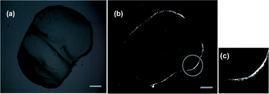 | ||
| Fig. 1 A typical polarized optical microscopy image of the periphery of a dried drop: (a) without cross-polar, (b) under cross-polar and on the right side (c), a specific magnified zone is shown. The scale bars in both (a) and (b) express 100 μm. | ||
Corresponding SEM characterization further reveals the details of such ordered MWNT-assemblies [Fig. 2]. We predict that the shown uniform bending orientation close to the edge of the deposit results from a geometrical constraint,16 i.e. the edge effect, which forces flexible MWNTs at the edge to arrange along the arc shaped triple-phase contact line [Fig. 2(c)].
 | ||
| Fig. 2 SEM images of the MWNT deposit formed at the circular rim from a droplet for different amplified times are represented in (a), (b) and (c), respectively. The scale bars correspond to 5 μm, 2 μm, and 1 μm respectively. | ||
For simplicity, in the following we only concentrate on the bending morphology of CNTs along the circular edge as is shown in Fig. 2(c), without deeply considering the surface anchoring functions. The geometrical anchoring plays an important role in the director orientation of the nematic liquid crystals,19 and thus the corresponding detailed research about CNTs lie in the future. It is the droplet-air and the droplet-substrate interfaces that impose such tangential bending alignment.
Besides, further experimental evidence, as for example the polarized Raman characterization, is provided in the Supporting Information (ESI†).
Theoretical method
During the experiments we noticed that, with time, the birefringent phenomenon appeared without the complete evaporation and could remain until the end, indicating the existence of liquid crystalline states in the last representation structures.So based upon the above experimental results for CNTs, reported like an extremely long semi-rigid macromolecular as discussed in ref. 13, 20–22, it is reasonable to analyze their liquid crystalline behavior via the well-known Frank elastic theory in the liquid crystal field (i.e. the Frank elastic constants kii related excess physical distortion free energy, f = K11/2 (▽·n)2 + K22/2 (n·(▽ × n))2 + K33/2 (n × (▽ × n))2, 23,24). Therefore we measured the Frank elastic constants K11 and K33 of the nanotubes from the concentric bending arrangement.
As is shown in [Fig. 3], we consider a certain position r in the liquid crystalline range ΔR labeled in the model (the model qualitatively reveals the evaporation-induced self organizing tendency in droplets of CNTs).
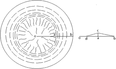 | ||
| Fig. 3 Schematic of CNT orientation in a dried droplet illustrating the bend arrangement along the circular edge in the range of ΔR (the distance between point a and b) and the radial direction distribution with graphic different densities inside the circle of radius R (R = R0 − ΔR, in which, R is the distance between point o and a, and R0 is the distance between o and b). Therein r denotes any position in the drying-formed liquid crystalline wedge ΔR (also with graphic different densities). And the right diagram describes the cross section through the origin in droplets, which illustrates that the highest nanotube distributive densities lie in the dividing line between radial and concentric regions and the distance between o and d denotes the rare nanotube distributive densities. | ||
As shown in the picture, CNTs have a concentric bending orientation along the circumference, and the involved elastic energy density contains the bending-deformation part of the CNT itself,15,25
| fconc (r) ≈ ED2/(96r2), | (1) |
| f′conc ≈ K33 / (2r2), | (2) |
| fradial(r) ≈ K11/2(1/r−1/(r−R0))2, | (3) |
| K11 ≈ (KBT) / (4D)·(L/D) | (4) |
To compute the total energies of the above two orientation conditions in the liquid crystalline wedge ΔR, we set α∼2° (the contact angle between the droplet-air and the droplet-substrate interfaces) for convenience.26 And then we deduce the total energies,
| Fradial ≈ παK11R0ln(ΔR/δ), | (5) |
| Fconc ≈ (παED2/48) [R0ln(R0/R) − ΔR] | (6) |
| F′conc ≈ (παK33) [R0ln(R0/R) − ΔR] | (7) |
Results and discussion
Measurements of Frank elastic constants K11 and K33 to nanotubes from concentric bending arrangement
For experimental R0 ≈ 288.28 μm and ΔR ≈ 5 μm noted in [Fig. 1(c), magnified area from the prominent zone in Fig. 1(b)] or in [Fig. 2], and additionally taking typical Young's modulus E ≈ 1011 Pa, length L ≈ 3 × 10⁻⁶ m and diameter D ≈ 1 × 10⁻⁸ m for our nanotubes, we obtain| Fradial ≈ 3.50 × 10⁻¹³J, | (8) |
| Fconc ≈ 5.73 × 10⁻¹⁴J, | (9) |
| F′conc ≈ 1.38 × 10⁻¹⁸J, | (10) |
Simultaneously, it is noticed that F′conc ≪ Fconc, so replacing the preset value of K33, in another perspective, we are trying to make CNTs' own bending elastic energy Fconc (E) equal to the new undetermined Frank bend free energy F′conc (K33′), in which K33′, different from K33, is unknown beforehand. And then we conclude K33′ ≈ ED2/48 (∼10−7 N), showing the E-relation.
From here we see that comparing CNTs with polymer liquid crystals, the behavior of CNTs in evaporating droplets becomes clear. And by neglecting the traditional much smaller K33 related Frank bend free energy in liquid crystals, we have examined the new introduced Frank curvature moduli K33′, which specifically emphasizes the CNTs' rigidity, relating the high Young's modulus E. Hence combining eqn (4), we have obtained the values of plane Frank elastic constants K11 and K33 (or K33′) to CNTs. Both of them come from the intertube interactions. They describe the splaying and bending distortions in defects of CNT-assemblies, respectively.
Certainly as we all know the interactions between molecules in the liquid crystal phase are very weak; and generally, the corresponding Frank elastic constants are also extremely weak, of the same order of magnitude (∼10−12 N). But here due to the high Young's modulus E-associated, the above estimated K33′ for CNTs is much larger. However, this is not surprising. In this work, we make experiments by evaporating dilute droplets slowly in order to ensure obtaining the ultimate dried equilibrium state, and then introduce a simple mathematical model (Fig. 3) so as to explore their Frank elasticity. Thus, under such circular restraint, it is believed that the obtained Frank bend moduli K33′ can reflect the nanotubes' bending deformations to some extent, and also this point will be further proved based upon studies of its related plane defects in the next section.
Effects of elastic anisotropy (K11 ≠ K33) on defects
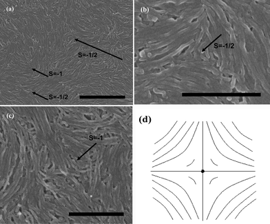
Because of the fact that K33′ ≫ K11 (∼10−11, calculated from eqn (4)), negative strength defects will be predominant and stable, as is shown in [Fig. 4]. Close to the central core of the −1/2 defects, CNTs bend conversely and arrange in the form of evident splay distortions [Fig. 4(c)]. This indicates the energy stability. First of all, the bending energy of individual nanotubes with enough length has been computed lower than the corresponding radial splaying one between tubes. And from a mathematical viewpoint, similar curves to Fig. 4(d) always have a tendency to bend and orient themselves conversely inward in order to obtain a differentiable nonzero vector field in the centre,27 which is also assumed to be one of the reasons for CNTs' bending like this. In addition, we have also observed the 1/2 defects [Fig. 4(a)], but it can be seen that their combined trends help to form the −1/2 splaying core.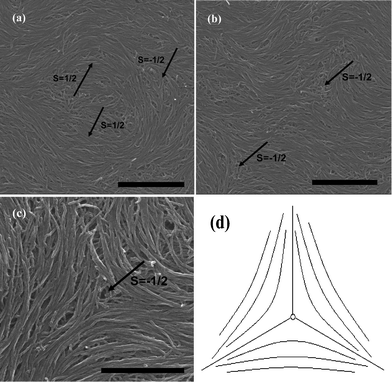 | ||
| Fig. 4 SEM images of splaying defective cores formed by long MWNTs during the end of the evaporation are represented in (a), (b) and (c), the scale bars correspond to 2 μm, 2 μm, and 1 μm respectively. (d) Denotes the mathematic model showing the field of the directions. | ||
Likewise, we take single-wall carbon nanotubes (SWNTs) in nearly the same length region as MWNTs to represent the above conclusions [Fig. 5]. It is not negligible that the defective characterization of SWNTs is much more perfect than that of MWNTs [Fig. 5(a) and 5(b)]. The result is important due to its implication for facilitating the formation of liquid crystalline structures on nanotubes. We believe that this is mainly because SWNTs have lower bending rigidity and stronger attractive inter-tube van der Waals (vdW) interactions. Besides, [Fig. 5(c)] exhibits the combination of ±1/2 defects, as is schematically shown in [Fig. 5(d)]. Similar to nematic polymers, it is a consequence of the defect interactions that two alike repel one another and two unlike attract one another. Considering the effect of elastic constant anisotropy, the director pattern in [Fig. 5(c)] just reveals the deduced result that K33′ ≫ K11 (the relationship for SWNTs are valued consistent with that for MWNTs in our experiments), with the central region rich in splay.28–30 Similar observations can also be detected from [Fig. 4(b)].
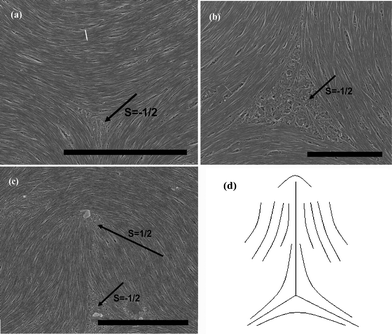 | ||
| Fig. 5 SEM images of splaying defective cores formed by long SWNTs during the end of the evaporation are represented in (a), (b) and (c), the scale bars correspond to 5 μm, 2 μm, and 5 μm respectively. (d) Denotes the schematic diagram of (c). | ||
As indicated above, the exploration of Frank elasticity to nanotubes can be extended to examine their liquid crystalline defective structures. It is clearly proved that magnitude relations of K11 and K33 can provide detailed informations about the geometry of these defects. In fact, from previous calculations, we find that variations in the tube dimensions and rigidity will easily produce differences between K11 and K33, leading to different types of defects. Frank elastic constants can concisely reflect how individual nanotubes will be arranged in the defects. Here, compared to regular liquid crystals,14 the new definition of K33′, associated with the high Young's modulus E, is believed to have common physical significance, reflecting the rigidity of nanotubes. The larger K33′ results in the appearing probability of splay deformations over that of the bending one between CNTs.
In contrast, we have also considered short MWNTs of the length ∼200 nm to make further investigations. From [Fig. 6], we still observe the known evident negative strength defects, especially for the occurrence of higher strength defects (s = −1 [Fig. 6(c) and 6(d)]). We can see that short nanotubes nearly keep straight. This is because following above analysis, the radial energy Fradial ≈ 2.33 × 10⁻¹⁴ J with the current K11 (∼2.07 × 10⁻¹² N, still existing K33′ ≫ K11), which is lower than the concentric bending energy Fconc. So it is obtained that short MWNTs do not bend and thereupon facilitate the −1 defect.
 | ||
| Fig. 6 SEM images of splaying defective cores formed by short MWNTs during the end of the evaporation are represented in (a), (b) and (c), the scale bars correspond to 1 μm, 500 nm, and 500 nm respectively. (d) Denotes the schematic diagram of (c). | ||
Overall, comparison between K11 and K33′ can explain these observed interesting defects, although their values are first touched like this. Especially, the large value of K33′ seems to be unreasonable originally, but the opposite may be true. First of all, the result fully originates from the solid experimental data. And next, the peculiarity is just the unique mechanical representations to CNTs. Only due to the unconsidered strong vdW attractions between tube walls, the real value of K33′ may be relatively smaller, as certain attractive interactions probably prompt the formation of liquid crystalline phases for rod-like molecules. But on the basis of our above analysis, it can be safely accepted that the value of K33′ is more likely to be larger than that of K11.
At last undeniably, close values of K11 and K33, and even K11 > K33, may also give a similar defect core structure.31 However, our analysis here does not contradict the statement in that reference, as various defects may occur with a certain value relationship between K11 and K33. The difference lies in that when K33 > K11, the negative strength defects will be stable and have a higher occurring probability, which is just consistent with our observations. Nevertheless, the values of Frank elastic constants K11 and K33 are still required to be further justified due to the existing uncertainties. We believe that the exploration of Frank elasticity and the defective properties of CNTs will contribute to their liquid crystalline formation and applications, especially for their successful combination with liquid crystals in displays.
Conclusions
Based upon the analogy between CNTs and liquid crystals, the Frank elasticity belonging to CNTs has been preliminarily studied, which has manifested related liquid crystalline defective properties as do ordinary liquid crystals. Short nanotubes behave like rigid rods, and longer ones are more like flexible polymers. However, CNTs have unique mechanical characteristics, which make them behave distinctively. The above studies on Frank elasticity of CNTs with enough length as well as the defective properties conclude that they can bend differently from rigid rods and can not form random coils like flexible polymers. As is shown in [Fig. 7(a) and (b)], CNTs can bend to achieve the large-area densely packed ordered structures. This indicates that it is advantageous for CNTs to form splay distortions, because they can easily maintain the conservation of the density of the system by means of bending.14 Thus, comparing with the outline [Fig. 7(c)], CNTs can increase the limitation of length for the occurrence of splay.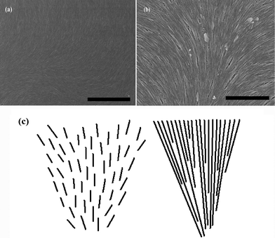 | ||
| Fig. 7 SEM images of the aggregating arrangement of long SWNTs with high density in their dried films are represented in (a) and (b). The scale bars correspond to 5 μm and 2 μm, respectively. (c) Schematically shows splay deformations separate for short and long rigid rod-like molecules. | ||
In summary, similarly to conventional liquid crystals, CNTs can also exist in the liquid crystalline state provided the control factors are properly regulated. We speculate that CNT solubility and dispersibility, purification, and interaction between tubes are all key parameters for the production of nano-ordered structures. Importantly, here we have explored the cause and effect from Frank elastic constants Kii and the vector fields of their liquid crystalline orientation defects, by which we may obtain more precise values of Kii. It is predicted that the determination of Kii will provide theoretical basis for the application of CNT orientation in many fields including carbon nano-composites in the liquid crystalline states, carbon nano-array production and electronic devices. Finally, we should mention that, based upon the introduced Frank continuum elastic theory, the analogy between CNTs and liquid crystals may be somewhat too drastic as far as real CNT systems are concerned. Such application does give quantitative analysis of the experimental phenomenon and order of magnitude comparison about Frank elastic constants K11 and K33, however. Herein, our work proves to be useful as a starting point for the exploration of the formation mechanism on liquid crystalline CNTs, and is worthwhile to be further studied.
Acknowledgements
We acknowledge discussions with Professor Ivan I. Smalyukh and Professor W. Jiang. This project is supported by the following foundations: National Science Foundation of China (10704051), Suzhou Nano Special Project (ZXG0713), Special Foundation of President of The Chinese Academy of Sciences, Science and Technology Support Project of Jiangsu Province (BE2009643), and Ministry of Science and Technology of the People's Republic of China (2010CB934700). Polarizing and SEM works were performed at the testing platform of Suzhou Institute of Nano-tech and Nano-bionics, Chinese Academy of Sciences.References
- W. H. Song, I. A. Kinloch and A. H. Windle, Science, 2003, 302(5649), 1363 CrossRef CAS.
- W. H. Song and A. H. Windle, Macromolecules, 2005, 38(14), 6181 CrossRef CAS.
- S. J. Zhang, I. A. Kinloch and A. H. Windle, Nano Letters, 2006, 6, 568 CrossRef CAS.
- P. K. Rai, A. N. G. Parra-Vasquez, J. Chattopadhyay, R. A. Pinnick, F. Liang, A. K. Sadana, R. H. Hauge, W. E. Billups and M. Pasquali, Journal of Nanoscience and Nanotechnology, 2007, 7(10), 3378 CrossRef CAS.
- V. A. Davis, L. M. Ericson, A. N. G. Parra-Vasquez, H. Fan, Y. H. Wang, V. Prieto, J. A. Longoria, S. Ramesh, R. K. Saini, C. Kittrell, W. E. Billups, W. W. Adams, R. H. Hauge, R. E. Smalley and M. Pasquali, Macromolecules, 2004, 37(1), 154 CrossRef CAS.
- P. K. Rai, R. A. Pinnick, A. N. G. Parra-Vasquez, V. A. Davis, H. K. Schmidt, R. H. Hauge, R. E. Smalley and M. Pasquali, Journal of the American Chemical Society, 2006, 128(2), 591 CrossRef CAS.
- S. Ramesh, L. M. Ericson, V. A. Davis, R. K. Saini, C. Kittrell, M. Pasquali, W. E. Billups, W. W. Adams, R. H. Hauge and R. E. Smalley, Journal of Physical Chemistry B, 2004, 108(26), 8794 CrossRef CAS.
- V. A. Davis, A. N. G. Parra-Vasquez, M. J. Green, P. K. Rai, N. Behabtu, V. Prieto, R. D. Booker, J. Schmidt, E. Kesselman, W. Zhou, H. Fan, W. W. Adams, R. H. Hauge, J. E. Fischer, Y. Cohen, Y. Talmon, R. E. Smalley and M. Pasquali, Nature Nanotechnology, 2009, 4(12), 830 CrossRef CAS.
- G. Scalia, C. von Buhler, C. Hagele, S. Roth, F. Giesselmann and J. P. F. Lagerwall, Soft Matter, 2008, 4(3), 570 RSC.
- S. D. Bergin, V. Nicolosi, S. Giordani, A. de Gromard, L. Carpenter, W. J. Blau and J. N. Coleman, Nanotechnology, 2007, 18(45), 455705 CrossRef.
- S. E. Moulton, M. Maugey, P. Poulin and G. G. Wallace, Journal of the American Chemical Society, 2007, 129(30), 9452 CrossRef CAS.
- S. Badaire, C. Zakri, M. Maugey, A. Derre, J. N. Barisci, G. Wallace and P. Poulin, Advanced Materials, 2005, 17(13), 1673 CrossRef CAS.
- C. Zakri and P. Poulin, Journal of Materials Chemistry, 2006, 16(42), 4095 RSC.
- H. Gleeson, Liquid Crystals Today, 1995, 5, 5 CrossRef.
- W. H. Song and A. H. Windle, Advanced Materials, 2008, 20(16), 3149 CrossRef CAS.
- Q. Li, Y. Zhu, I. Kinloch and A. H. Windle, J. Phys. Chem. B, 2006, 110(28), 13926 CrossRef CAS.
- S. Zhang, Q. Li, I. Kinloch and A. H. Windle, Langmuir, 2009, 26, 2107 CrossRef.
- Y. Lin, A. M. Rao, B. Sadanadan, E. A. Kenik and Y. P. Sun, J. Phys. Chem. B, 2002, 106(6), 1294 CrossRef CAS.
- O. D. Lavrentovich, Physical Review A, 1992, 46, 722 CrossRef.
- S. J. Zhang and S. Kumar, Small, 2008, 4(9), 1270 CrossRef CAS.
- C. Zakri, Liquid Crystals Today, 2007, 16(1), 1 CrossRef CAS.
- A. Somoza, C. Sagui and C. Roland, Physical Review B, 2001, 63(8), 081403 CrossRef.
- P. De Gennes, Molecular Crystals and Liquid Crystals, 1977, 34(8), 177 CrossRef CAS.
- A. Ciferri, W. Krigbaum, R. Meyer, Polymer liquid crystals. Academic PressNew York: 1982 Search PubMed.
- F. Frank, Discussions of the Faraday Society, 1958, 25, 19 RSC.
- I. I. Smalyukh, O. V. Zribi, J. C. Butler, O. D. Lavrentovich and G. C. L. Wong, Physical Review Letters, 2006, 96(17), 177801 CrossRef.
- P. Manfredo do Carmo., Differential Geometry of Curves and Surfaces, 2004, 175 Search PubMed.
- G. S. Ranganath, Molecular Crystals and Liquid Crystals, 1983, 97, 77 CrossRef CAS.
- W. Song, H. Tu, G. Goldbeck-wood and A. H. Windle, Liquid Crystals, 2003, 30, 775 CrossRef CAS.
- W. Song, H. Tu, G. Goldbeck-wood and A. H. Windle, J. Phys. Chem. B, 2005, 109, 19234 CrossRef CAS.
- D. H. Steven and L. T. Edwin, Physical Review Letters, 1989, 62, 1993 CrossRef.
Footnote |
| † Electronic supplementary information (ESI) available. See DOI: 10.1039/c1ra00303h |
| This journal is © The Royal Society of Chemistry 2011 |
