Mechanical actuation of ion channels using a piezoelectric planar patch clamp system
Eric
Stava†
*a,
Minrui
Yu
a,
Hyun Cheol
Shin
b,
Hyuncheol
Shin
a,
Jonathan
Rodriguez
a and
Robert H.
Blick
a
aDepartment of Electrical and Computer Engineering, University of Wisconsin-Madison, 1415 Engineering Drive, Madison, WI 53706, USA
bMaterials Science Program, University of Wisconsin-Madison, 1415 Engineering Drive, Madison, WI 53706, USA
First published on 21st October 2011
Abstract
High-throughput screening of ion channels is now possible with the advent of the planar patch clamp system. This system drastically increases the number of ion channels that can be studied, as multiple ion channel experiments can now be conducted in parallel. However, due to tedious, usually pressure-driven mechanotransduction techniques, there has been a slow integration of this technology into the field of mechanosensitive ion channels. By implementing a piezoelectric quartz substrate into a planar patch clamp system, we show that the patch clamp substrate itself can be used to mechanically actuate ion channels. The piezoelectric substrate transduces an external, applied electric field into a mechanical tension, so precise actuation of the membrane can be accomplished. By applying this electric field only to the outer edges of the substrate, no ulterior electric field is created in the vicinity of the membrane during actuation. Further, with resonant frequencies ranging from 1 kHz to 200 MHz, quartz substrates can be used to apply a wide range of time-varying tensions to cell membranes. This will allow for new and instructive investigations into the dynamic mechanotransductive properties of ion channels.
Introduction
Patch clamping is the traditional method for investigating the electrical properties of ion channels.1,2 Under this technique, the experimenter uses a microcontroller to position a micropipette in close proximity to the ion channel-containing cell. Suction control is used to form a tight seal between the cell membrane and the micropipette, and electrodes inside the micropipette and in the cell bath measure ionic currents flowing across the cell membrane. Fluctuations in these electrical recordings correspond to changes in the conductance state of ion channels embedded in the cell membrane, and fluctuations from a single ion channel can be resolved.While this method has been widely successful,2 a more efficient method, known as planar patch clamping, has been developed to streamline the investigation of ion channels.3 With this technique, the aforementioned micropipette is replaced with a pore-containing planar substrate. Instead of using a micromanipulator to bring a micropipette in close proximity to a cell, suction is used to guide the cell directly to the micron-sized pore. Electrodes immersed in baths on either side of the substrate can then electrically detect ion channel activity.
Planar patch clamping can be done quickly, requires minimal training, and commercially available arrays of planar patch clamping systems are now capable of performing multiple patch clamp experiments in parallel.4 These technological advances make ion channel research much more efficient and have enhanced the overall throughput of ion channel experiments.5
We now show that this technology can be used to streamline the investigation of mechanosensitive ion channels (MSCs). MSCs are ion channels that respond to an applied mechanical stress through a change in their conductance state, altering the flux of ions across their cell membrane.6–10 By transducing mechanical energy into an electrical response, MSCs constitute the fundamental biological units responsible for mechanosensation. Examples of their function include touch, hearing, and osmoregulation. Studies involving reconstituted MSCs and other ion channels into lipid bilayers reveal that tension in the lipid bilayer itself induces mechanotransduction.11–15
Common techniques for mechanically stimulating MSCs in vitro include: applying positive and negative pressures;16–18 mechanically pulling or pushing the cell membrane with patch pipettes,19–21 glass capillaries,22 glass styluses23 or carbon fibers;24,25cell swelling by hypoosmotic media26 or direct pressure;27insertion of amphipaths;28 and manipulating magnetic beads embedded in the cell membrane.29,30 Most of these techniques require visualization of the cell (pressure application and cell swelling require visualization to calculate the level of tension applied; mechanical stretching requires visualization to make contact with the cell without rupturing it), which does not allow these methods to be integrated into a high-throughput system. Also, when using integrins and amphipaths, the exact quantity and location of the molecules used to apply tension is not directly controllable, so the profile of the applied tension is not well-defined.
In contrast to these techniques, piezoelectric actuation of the substrate itself requires no visualization (since tension is induced in the plane of the membrane), no insertion of particles, and is directly controllable with a voltage source. It has already been shown that ion channel experiments can be performed with planar lipid bilayers supported by a quartz substrate.31 Here, we show that these substrates will deform in the presence of an applied electric field, and that this deformation will induce tension to the lipid bilayer.
In the experiments outlined below, the piezoelectric material used is single-crystal quartz. Single-crystal quartz has a lower dielectric loss factor and dielectric constant over borosilicate glass, and in ion channel experiments it has been shown that quartz yields drastically reduced noise levels over borosilicate glass.31,32
Single-crystal quartz consists of silicon dioxide molecules arranged in a crystalline formation. The piezoelectric nature of this material is due to the fact that oxygen has a higher electronegativity over silicon. Electrons naturally displace from the center of the silicon-oxygen bond, tending toward the oxygen molecules, and form an electric dipole within each unit cell of the crystal. In the presence of an applied electric field, this dipole causes the silicon and oxygen molecules to displace from their original locations (see Fig. 1). The level of molecular displacement corresponds precisely with the strength of the electric field. This displacement can cause the crystal to stretch, compress, or shear, depending on the orientation of the crystal with respect to the field. This ability to mechanically deform in the presence of an electric field is known as the converse piezoelectric effect.33,34
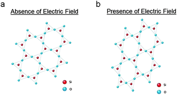 | ||
| Fig. 1 A simplified 2-D representation of a quartz crystalline lattice in the (a) absence and (b) presence of an applied electric field. Mechanical stretching is due to the converse piezoelectric effect. | ||
By confining this electric field solely to the outer edges of the substrate, the entirety of the substrate will still deform, though the electric field will be negligible near the center of the substrate. In this way, a micron-sized pore formed in the center of the substrate can mechanically deform without incurring any ulterior electric fields in its vicinity. Any lipid bilayer fixed over the pore can then actuate mechanically while another, separate pair of electrodes can be used to excite it electrically. Mechanical and electrical probing of ion channels embedded in the lipid bilayer can thus be performed independently.
Further, as this mechanical tension is voltage-controlled, a wide range of time-varying mechanical waveforms can be applied to the cell membrane. With resonant frequencies ranging from 1 kHz to 200 MHz,35 piezoelectric quartz substrates can be used to investigate the dynamic mechanotransductive properties of cell membranes, membrane-embedded proteins, and MSCs.
Materials and methods
Piezoelectric patch clamp system
The fabrication of micron-sized pores in single-crystal quartz is reported elsewhere.36 Briefly, a UV absorbent liquid confined to the backside of the quartz substrate absorbs energy when pulsed by an excimer laser. This increase in energy is accompanied by a jump in temperature and pressure at the liquid/substrate interface, inducing pore formation.Quartz substrates drilled in this manner are fixed to a block of polydimethylsiloxane (PDMS), which itself contains embedded electrodes. Electrodes are integrated by placing them inside a partially cured PDMS block, and then allowing the curing to finalize. A PDMS o-ring is fixed above the quartz substrate, which is used to confine the electrolyte solution above the quartz substrate. Another electrode-embedded PDMS block is placed above the o-ring. The overall structure is then fixed to a TwistTop Vial Cap (Dot Scientific, Inc., Burton, MI, USA), which connects to a Nanion Port-A-Patch System (Nanion Technologies GmbH, Munich, Germany). Millimetre-sized holes in the cap and both electrode-embedded PDMS blocks confine the electrolyte solution and allow for electrical contact to the patch clamp amplifier (HEKA EPC 10 Single, HEKA Electronik GmbH, Lambrecht, Germany).
Quartz substrates with resonant frequencies of 10 MHz were used, corresponding to a substrate thickness of 186 μm. Quartz substrates were extracted from quartz resonators (IQD Frequency Products Ltd, Palo Alto, CA, USA), after which micron-sized pores were drilled.36 Prior to fixing a quartz substrate to the PDMS system, the quartz was cleaned and made hydrophilic by 20 min of immersion in a heated piranha solution (3![[thin space (1/6-em)]](https://www.rsc.org/images/entities/char_2009.gif) :
:![[thin space (1/6-em)]](https://www.rsc.org/images/entities/char_2009.gif) 1 ratio of H2SO4:(30%)H2O2).
1 ratio of H2SO4:(30%)H2O2).
Physiological system
Lipid bilayers were formed via bursting of giant unilamellar vesicles (GUVs). The GUVs were formed by the electroformation technique,37 using a Vesicle Prep Pro (Nanion Technologies GmbH, Munich, Germany). 1,2-Diphytanoyl-sn-Glycero-3-Phosphocholine (DPhPC; Avanti Polar Lipids, Inc., Alabaster, AL, USA) was used as the lipid, and droplets of 5 mg mL−1 of lipid in chloroform were used in the electroformation technique. 1 M KCl was used as the electrolyte solution, which was placed inside the o-rings of each PDMS block, above and below the quartz chip. Once the bilayer formed, Alamethicin (Sigma-Aldrich, St. Louis, MO, USA) was injected into the electrolyte solution. Voltage clamping was achieved viaAg/AgCl electrodes immersed in each electrolytic chamber, and were connected to the patch clamp amplifier. Shortly after Alamethicin injection, distinct current bursts were detected, verifying the creation of Alamethicin ion channels. We then applied voltages to the PDMS-embedded electrodes to induce piezoelectric actuation of the quartz substrate and recorded the resulting current responses.Results and discussion
Quartz actuation
The substrate used for actuation is made of AT-cut single-crystal quartz. This is a common cut of quartz, owing to its high temperature-frequency stability and its lack of stray coupling between vibrational modes. It is fabricated by cutting a quartz crystal at 35° 15` to the optical axis (Fig. 2a). An electric field applied across the thickness of this crystal will activate its thickness shear mode of vibration (Fig. 2b). The resonant frequency of this mode is dependent on the thickness of the substrate, and is calculated as f = v/(2t), where f is the resonant frequency, ν is the mode velocity, and t is the substrate thickness. When exciting the thickness shear mode of AT-cut quartz, the mode velocity can be calculated using the following: , where ρ is the density of quartz and C′66 is the rotated stiffness constant for the thickness shear mode. For AT-cut quartz, ρ = 2.65 g cm−3 and C′66 = 3.59 × 10¹⁰ N m−1, yielding a mode velocity of approximately 3680 m s−1. For a 10 MHz AT-cut quartz crystal, then, the thickness of the substrate is 184 μm.38,39
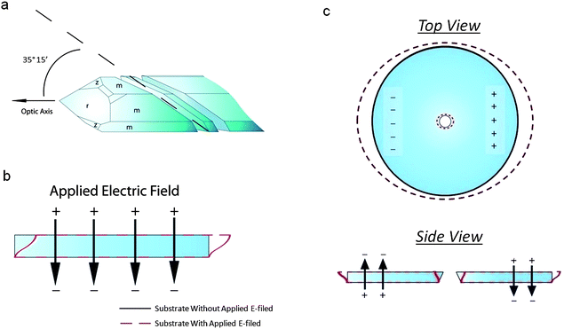 | ||
| Fig. 2 (a) Crystallographic orientation of an AT-cut quartz substrate. The crystal is cut 35° 15′ to the optical axis. (b) Thickness shear mode of an AT-cut quartz substrate. When an electric field is applied across the thickness of the substrate, the top face moves laterally with respect to the bottom face. When the bottom face is fixed, only the top face moves. (c) Side and top views of the piezoelectric actuation of a pore in an AT-cut quartz substrate. Two electric fields of opposite direction across the thickness of the substrate are used to induce opposing thickness shear modes. This causes a deformation in the pore, located in the center of the substrate. | ||
By applying a single, static electric field normal to the substrate, we excite the thickness shear mode of the substrate. However, since the electric field is static, the substrate does not vibrate as it would under resonance. Instead, the upper face of the substrate simply displaces by an amount dependent on the magnitude of the field with respect to the fixed, lower face (Fig. 2b). By applying two DC fields opposite in polarity but equal in magnitude to the outer edges of the substrate, we excite opposing thickness shear modes in the substrate (Fig. 2c). Since we have formed our pores through the center of the top face of each substrate, each of our pores are located directly between these two thickness-shear modes. Depending on the polarity of the applied fields, this will result in either an expansion or a contraction of the top face of the quartz pore. As such, any membrane fixed to the top face of our pore will undergo a compressive or tensile strain.
To quantify the mechanical effects an electric field has on this quartz system, we applied various levels of static voltage to a single-crystal quartz substrate while visualizing it with a scanning electron microscope. Fig. 3 shows the effect of applying 5.2 × 10⁶ V m−1 across a quartz substrate containing a pore approximately 35 μm in diameter. In the presence of the electric field, opposing thickness-shear modes are excited in the substrate, stretching the pore. We found that the pore increases in diameter by 0.9 μm in the x-direction and 2.0 μm in the y-direction. The inequivalent values of expansion in the x- and y-directions are due to the fact that the thickness shear mode of the substrate is at an angle to the x- and y-axes.
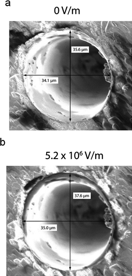 | ||
| Fig. 3 SEM images of a ∼ 35 μm diameter quartz pore in the (a) absence and (b) presence of applied electric fields. Electric fields were applied in the configuration shown in Fig. 2c. Increasing the electric field increases the diameter of the pore. The disparate increase in diameter in the x- and y-directions is due to the fact that the thickness shear mode was excited at an angle to the x- and y-axes. | ||
We applied multiple values of electric fields to the quartz substrate and measured each expansion under a scanning electron microscope. The results are shown in Fig. 4. We found that the pore diameter increases in a nearly linear fashion with electric field magnitude. In the x-direction, this corresponds to an increase of 0.11 μm/(MV m−1); in the y-direction, 0.36 μm/(MV m−1).
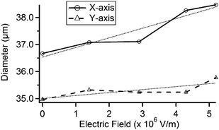 | ||
| Fig. 4 Plot of the x-axis and y-axis diameters at multiple applied electric fields using the pore shown in Fig. 3. The x- and y-axes are defined as the horizontal and vertical directions in Fig. 3, respectively. Lightly-dashed lines represent linear fits. | ||
Piezoelectric planar patch clamp system
Given that the mechanical properties of single-crystal quartz are precisely controlled by an electric field, we now consider its use as a substrate in an ion channel system. It has already been shown that these substrates are capable of suspending lipid bilayers with high seal resistances, and that low-noise ion channel recordings are possible with quartz.31,32 We now provide a technique for actuating the quartz piezoelectrically while simultaneously measuring the conductance properties of the ion channels. In contrast with previous results from ion channels formed over a quartz substrate, where lipids immersed in an organic solvent formed the bilayer, this technique uses GUV bursting to form the bilayer. This is due to the fact that, in the previous experiment, the organic solvent/lipid mixture formed a lipid-filled annulus surrounding the bilayer. In this previous experiment, any increase in pore diameter would result in additional lipids entering the bilayer–and minimal increase in bilayer tension. Using GUV bursting, however, ensures that the lipid bilayer adheres to the quartz substrate via hydrophillic interactions. Therefore, no lipid-filled annulus surrounds the lipid bilayer. When the quartz pore expands, tension will now be placed on the lipid bilayer.For an AT-cut single-crystal quartz substrate containing a laser-drilled, micron-sized pore, one must apply two electric fields, opposite in polarity, to either side of the substrate in order to excite opposing thickness shear modes (see Fig. 2c). This excitation will have the effect of stretching or compressing the top face of the pore. Any lipid membrane fixed to this top face, then, will incur a stress due to this effect.
The piezoelectric patch clamp system is shown in Fig. 5. We confine the electric fields used to actuate the quartz to the outer edges of the quartz substrate. This was done to minimize any electrical effects these fields may have on the lipid bilayer. To further separate these fields from the lipid bilayer, electrodes embedded in blocks of PDMS were used to create the electric field. Since these electrodes make no physical contact with the quartz substrate, the effect from any stray currents arising from the electrodes is negligible.
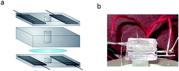 | ||
| Fig. 5 (a) Piezoelectric planar patch clamp system. Two blocks of PDMS with embedded electrodes are used to apply the electric fields. The quartz substrate is fixed between these blocks. A PDMS o-ring is placed atop the quartz substrate and is used to confine the electrolytic solution above the quartz. (b) Photograph of the setup described in (a). | ||
To confine the electrolyte solution used for ion channel analysis, we use small o-rings formed in the center of each electrode-embedded PDMS block. This electrolyte confinement allows for simple integration of the ion channel system with our piezoelectric substrate. By placing an electrolyte-containing, electrode-embedded PDMS block above and below the quartz substrate, we can piezoelectrically actuate the quartz substrate while simultaneously making electrical measurements with the electrolyte solution. Details regarding the development of this system are found in the Materials and methods section.
Electrical simulation results
The setup shown in Fig. 5 was simulated to investigate the magnitude of the electric field in the vicinity of the quartz pore. This simulation was conducted to gauge the effect that stray electric fields may have on the membrane over the pore. We approximate 0.2 MV m−1 to be an appropriate upper limit for electrical influence in the vicinity of the pore, since this would correspond to 1 mV across a 5 nm bilayer.Comsol Multiphysics software (Comsol, Inc., Burlington, MA, USA) was used to construct the finite element method (FEM) simulation. The structure shown in Fig. 5a was constructed for our electrodynamic simulation. A static voltage of 200 V was applied to two diagonally facing PDMS-embedded metal electrodes, while the two other electrodes were held at ground (Fig. 6a,b). All other materials were left floating, allowing electric fields to penetrate them. Proper values were given for the dielectric properties all of the materials.
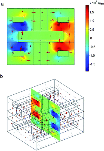 | ||
| Fig. 6 Finite element simulation results of the electric field in the system shown in Fig. 5. Results are shown in (a) front and (b) angled views. A voltage of 200 V is applied to two diagonally-located electrodes, while the other two electrodes are held at ground. The electric fields on the outer edges of the quartz substrate are on the order of 104 V m−1. The electric field in the vicinity of the pore, however, is approximately 0.45 V m−1. This is equivalent to applying 2.25 nV across a 5 nm lipid membrane, which is very much negligible. This indicates that voltages capable of deforming the quartz pore will have no impact on the electric field in the vicinity of the pore. This is crucial for isolating electrical and mechanical effects on membrane-bound proteins. | ||
The results of this simulation are shown in Fig. 6. We found that the application of 200 V across the PDMS-embedded electrodes yields approximately 0.01 MV m−1 across the outer edge of the substrate. Using our experimentally-derived linear fits (see Fig. 4), this accounts for a shift in pore area by approximately 3 Å2. This is just an order of magnitude lower than that necessary for significant mechanotransduction of Alamethicin ion channels11 and, in the following section, we show that this value is sufficient for noticeable changes in ion channel conduction.
This change in area, which is accomplished by applying 0.01 MV m−1 to the outer edges of the substrate, yields an electric field of only 0.45 V m−1 in the vicinity of the pore. This is seven orders of magnitude lower than our previously-specified upper limit (i.e., this is seven orders of magnitude less than the electric field formed by applying 1 mV across a 5 nm thick membrane). Therefore, we can safely assume that any stray fields created by the PDMS-embedded electrodes for the range of voltages used have a negligible effect on the membrane or any ion channels embedded within.
Ion channel results
To ensure that any deformation in the quartz substrate will result in an applied tension in the lipid bilayer, it is crucial to fix the bilayer to the top face of the quartz substrate surrounding the pore. We accomplished this in two steps. First, the quartz substrate was made hydrophilic prior to experimentation by treating it with a piranha solution (details given in Materials and methods section). This ensures that any polar lipid headgroups in the vicinity of the top face of the substrate will be attracted to the substrate via hydrophilic interactions. Second, we formed the bilayer by bursting a GUV over the pore. This is in contrast to other bilayer formation techniques (e.g., the painting and folding methods), which create an annulus of lipid molecules surrounding the pore. Instead, by using the GUV bursting technique, a single bilayer of lipid molecules lies over the pore and the surrounding top face of the substrate.To test the stability of the lipid bilayer under piezoelectric actuation, we measured the change in leakage current across the bilayer while applying an electric field to the outer edges of the substrate. Fig. 7a shows the leakage current across the bilayer under a 50 mV holding potential before and after the application of 1 × 10⁴ V m−1 to the outer edges of the quartz substrate. An electric field of this magnitude is sufficient to affect the conductance probabilities of ion channels embedded in the lipid bilayer (see results below). However, in the absence of ion channels, we found that this field results a shift of only 280 fA, which is much less than the response from a single channel. Further, since the leakage currents in these cases were approximately 1 pA, the seal resistance of the system is ∼50 GΩ. This seal resistance is large enough to resolve single channel conductances.
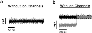 | ||
| Fig. 7 (a) The black and gray traces correspond to leakage current across a lipid bilayer before and after piezoelectric actuation, respectively. These recordings were made in the absence of embedded ion channels. To induce piezoelectric actuation, an electric field of 1 × 10⁴ V m−1 is applied to the substrate. The holding potential is 50 mV, giving a seal resistance of ∼ 50 GΩ. The change in current with piezoelectric actuation is 280 fA, which is less than the noise level of the system. (b) Black and gray traces correspond to recorded current before and after piezoelectric actuation, respectively, from a lipid bilayer with embedded Alamethicin ion channels. In this case, the system is under a negative holding potential. The current traces shows that, while the conductance of the system increases with piezoelectric actuation, it also occasionally reaches levels found prior to actuation. This is a result of increasing the probability of occupying larger conductance states, while not affecting the actual values of the conductance states. | ||
In order to detect the influence of this piezoelectric actuation on ion channels embedded in a lipid bilayer, we inserted the ion channel Alamethicin into the system. We chose this ion channel because it can form by simple insertion into the electrolyte solution. Therefore, we were able to test the effect of the piezoelectric system on the same bilayer, with and without embedded ion channels.
Considerable research has already been conducted on the ion channel Alamethicin.40–42 Some of this research concerns the influence of membrane tension on embedded Alamethicin ion channels, which was accomplished by applying pressure to a patch pipette.11 This research shows that, although a change in membrane tension does not significantly affect the individual conductance states of the ion channel, it will affect the probability of forming these states. It has been shown that the probability of an Alamethicin ion channel occupying the next highest conductance state (that is, the probability of the ion channel containing a single, additional Alamethicin monomer) increases exponentially with membrane tension.11
To test the effect of our piezoelectric patch clamp system on a collection of these ion channels, we inserted a solution of Alamethicin peptides into the electrolyte solution following the formation of a lipid bilayer. After a few minutes, in the absence of any piezoelectric actuation, distinct current bursts were identified, verifying ion channel formation. We recorded these current traces, and then varied the electric field applied to the outer edges of the quartz substrate.
Noticeable variations in the current bursts are apparent with piezoelectric actuation, as shown in Fig. 8. Fig. 8a is a current trace from a collection of Alamethicin ion channels before and after piezoelectric actuation. This figure shows that the macroscopic current slowly increases once 5 × 10³ V m−1 is applied to the outer edges of the substrate. Since the magnitude of this electric field is less than that which was applied to the bilayer in the absence of ion channels (see Fig. 7a), this increase in current is due to a change in the ion channel conductance and not the lipid bilayer. Also, since an electric field of this magnitude is negligible in the vicinity of the pore (see Fig. 6), we must conclude that this change in conductance is due to the increased probability of Alamethicin ion channels to occupy larger conductance states with increased tension.
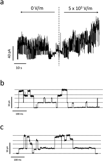 | ||
| Fig. 8 (a) Sample current trace of Alamethicin ion channels before and after applying a voltage bias to the PDMS-embedded electrodes used to induce piezoelectric actuation. The time of voltage application is indicated by the dashed, vertical line. Due to the piezoelectric nature of the quartz substrate, the electric field created by the electrodes mechanically actuates the substrate, inducing tension in the lipid membrane. This increase in tension increases the probability of Alamethicin ion channels to form larger conductance states, which is apparent in this trace. (b) and (c) represent zoomed-in current traces of Ala ion channel formation before and after applying piezoelectric deformation, respectively. Dashed gray lines represent discrete conductance states (note that some of these states represent combinations from multiple ion channels). A comparison of (b) and (c) reveals an increased tendency for the Ala ion channels to exist in excited, non-ground level states with piezoelectric deformation. | ||
Fig. 8b and 8c further evidence this fact. Fig. 8b and 8c show detailed traces of the current before and after piezoelectric actuation, respectively. It is apparent from the figures that duration spent in larger conductance states increase with increased piezoelectric actuation. This, again, demonstrates the preference for the ion channels to occupy larger conductance states with increased bilayer tension.
Fig. 9 shows current histograms at different levels of applied electric field, all under a negative holding potential. These histograms show that the conductance of the system increases with increased applied electric field. Also, the system does return to the same lower conductance levels with increased electric field; this is also shown in Fig. 7b. This indicates that only the probability to occupy larger conductance states increases with electric field, and not the value of the conductance states themselves.
 | ||
| Fig. 9 Current histograms due to the Alamethicin ion channels when different levels of electric field are applied, all under the same negative holding potential. The ion channels are more likely to occupy larger conductance states with increased electric field. This is due to the increase in membrane tension on the ion channels, which itself is due to the piezoelectric actuation of the system. | ||
It should also be noted that the values of the electric fields used in Fig. 9 are similar to those shown for a lone bilayer in Fig. 7a, as well as the FEM simulation shown in Fig. 6. In other words, the change in current given by these histograms is not only due to the ion channels themselves, but, since the stray fields in these cases are so small, it is due to a change in the mechanical tension applied to these ion channels.
Conclusions
We have shown that a laser-drilled, single-crystal quartz substrate can be used to probe the mechanotransductive properties of ion channels. By exciting opposing thickness-shear modes in the substrate, one can finely tune the diameter of the pore. This mechanically actuates the lipid membrane fixed over the pore, which can then be transduced into an electrical signal by embedded mechanosensitive ion channel proteins.Finite element simulations show that electrical fields sufficient to induce tension in the substrate yield negligible stray fields in the vicinity of the pore. This guarantees the independence of electrical and mechanical effects applied to the system. Further, changes in the dimensions of the pore can easily be visualized with SEM. These images have allowed us to quantify the relationship between pore dimension and applied static field. Due to the linear nature of this relationship, field effects can be scaled down to predict Angstrom-sized mechanical displacements in the substrate.
The incorporation of Alamethicin ion channels into this system has further verified its capability to mechanically perturb membrane-bound proteins. We show that the probability of finding these channels in larger conductance states increases with increased applied static voltage, owing to increased mechanical tension in the substrate. This effect has been shown before, but only when tension was applied via changes in pipette pressure. In our system, an in-plane tension is applied to the membranevia on-chip patch clamping.
Our piezoelectric patch clamp system requires little additional fabrication when compared to conventional planar patch clamp systems. Currently, high-throughput planar patch clamp systems have already begun streamlining the investigation of voltage- and ligand-gated ion channels. It is anticipated that our piezoelectric system will introduce this advantage to the field of mechanosensitive ion channels as well.
Acknowledgements
The authors would like to acknowledge funding by NSF (MRSEC) as well as NIH (NIBIB 1R01EB009103-01) and WID (135A045).The authors are grateful to Justin Williams, Robert Pearce, and Ching Kung for their help and assistance. The authors are also grateful to Niels Fertig (Nanion Technologies) for helpful discussions.
References
- O. P. Hamill, A. Marty, E. Neher, B. Sakmann and F. J. Sigworth, Pfluegers Arch., 1981, 391, 85–100 CrossRef CAS.
- Ion channels of excitable membranes, ed. B. Hille, Sinauer, Sunderland, 3rd edn, 2001 Search PubMed.
- N. Fertig, R. H. Blick and J. Behrends, Biophys. J., 2002, 82, 3056–3062 CrossRef CAS.
- A. Brüggemann, S. Stoelzle, M. George, J. C. Behrends and N. Fertig, Small, 2006, 2, 840–846 CrossRef.
- C. Wood, C. Williams and G. J. Waldron, Drug Discov., 2004, 9, 434–441 CAS.
- C. E. Morris, J. Membr. Biol., 1990, 113, 93–107 CrossRef CAS.
- C. Kung, Nature, 2005, 436, 647–654 CrossRef CAS.
- B. Martinac, J. Cell Sci., 2004, 117, 2449–2460 CrossRef CAS.
- E. Perozo, Nat. Rev. Mol. Cell Biol., 2006, 7, 109–119 CrossRef CAS.
- Mechanosensitive ion channels, ed. O. P. Hamill, Academic Press, San Diego, 2007, vol. 58, part A Search PubMed.
- L. R. Opsahl and W. W. Webb, Biophys. J., 1994, 66, 71–74 CrossRef CAS.
- M. Goulian, O. N. Mesquita, D. K. Fygenson, C. Nielsen, O. S. Andersen and A. Libchaber, Biophys. J., 1998, 74, 328–337 CrossRef CAS.
- F. Sachs, Physiology, 2010, 25, 50–56 CrossRef CAS.
- E. Perozo, A. Kloda, D. M. Cortes and B. Martinac, Nat. Struct. Biol., 2002, 9, 696–703 CrossRef CAS.
- P. Wiggins and R. Phillips, Biophys. J., 2005, 88, 880–902 CrossRef CAS.
- F. Guharay and F. Sachs, J. Physiol., 1984, 352, 685–701 CAS.
- O. P. Hamill, Single-Channel Recordings, Plenum, New York, 1983, pp. 451–471 Search PubMed.
- P. Brehm, R. Kullberg and F. Moody-Cobett, J. Physiol., 1984, 350, 631–648 CAS.
- M. J. Davis, J. A. Donovitz and J. D. Hood, Am. J. Physiol. Cell Physiol., 1992, 262, C1083–C1088 CAS.
- N. Sasaki, T. Mitsuiye and A. Noma, Jpn. J. Physiol., 1992, 42, 957–970 CrossRef CAS.
- F. Sachs and C. E. Morris, Rev. Physiol., Biochem., Pharmacol., 1998, 132, 1–77 CrossRef CAS.
- T. Zeng, G. C. L. Bett and F. Sachs, Am. J. Physiol. Heart Circ. Physiol., 2000, 278, H548–H557 CAS.
- A. Kamkin, I. Kiseleva and G. Isengerg, Cardiovasc. Res., 2000, 48, 409–420 CrossRef CAS.
- J.-Y. L. Guennec, E. White, F. Gannier, J. A. Argibay and D. Garnier, Exp. Physiol., 1991, 76, 975–978 Search PubMed.
- E. White, J.-Y. L. Guennec, J. M. Nigretto, F. Gannier, J. A. Argibay and D. Garnier, Exp. Physiol., 1993, 78, 65–78 CAS.
- G. N. Tseng, Am. J. Physiol. Cell Physiol., 1992, 262, C1056–C1068 CAS.
- N. Hagiwara, H. Masuda, M. Shoda and H. Irisawa, J. Physiol., 1992, 546, 285–302 Search PubMed.
- B. Martinac, J. Adler and C. Kung, Nature, 1990, 348, 261–263 CrossRef CAS.
- M. Glogauer, J. Ferrier and C. A. G. McCulloch, Am. J. Physiol. Cell Physiol., 1995, 269, C1093–C1104 CAS.
- Mechanosensitivity in Cells and Tissues, ed. A. Kamkin and I. Kiseleva, Springer, New York, 2008 Search PubMed.
- E. Stava, M. Yu, H. C. Shin and R. H. Blick, IEEE Trans. NanoBiosci., 2010, 9, 307–309 CrossRef.
- R. A. Levis and J. L. Rae, Biophys. J., 1993, 65, 1666–1677 CrossRef CAS.
- G. Lippman, Journal de Physique, 1881, 10, 381–394 Search PubMed.
- J. Curie and P. Curie, C.R. Acad. Sci., 1880, 91, 294–295 Search PubMed.
- A. P. Gnädinger, Advances in electronics and electron physics, Academic Press, New York, 1980, vol. 51 Search PubMed.
- M. Yu, H. C. Shin, E. J. Stava, D. J. Kreft and R. H. Blick, submitted.
- M. I. Angelova, Giant Vesicles, John Wiley Sons Ltd., West Sussex, England, 2000 Search PubMed.
- Piezoelectricity, ed. W. J. Cady, Dover Publications, New York, 1964 Search PubMed.
- Handbook of Piezoelectric materials, ed. J. P. Buchanan, Philco Co., 1954 Search PubMed.
- G. A. Wooley and B. A. Wallace, J. of Memb. Biol., 1992, 129, 109–136 Search PubMed.
- J. E. Hall, I. Vodyanoy, T. M. Balasubramanian and G. R. Marshall, Biophys. J., 1984, 45, 233–247 CrossRef CAS.
- D. S. Cafiso, Annu. Rev. Biophys. Biomol. Struct., 1994, 23, 141–165 CrossRef CAS.
Footnote |
| † Present address: Institut für Angewandte Physik und Zentrum für Mikrostrukturforschung, Universität Hamburg, Jungiusstrasse 11, D-20355 Hamburg, Germany. Tel: ++49 (0)40-42838-2910; E-mail: estava@physnet.uni-hamburg.de. |
| This journal is © The Royal Society of Chemistry 2012 |
