Converting steady laminar flow to oscillatory flow through a hydroelasticity approach at microscales†
H. M.
Xia
*,
Z. P.
Wang
,
W.
Fan
,
A.
Wijaya
,
W.
Wang
and
Z. F.
Wang
Singapore Institute of Manufacturing Technology, 71 Nanyang drive, Singapore 638075. E-mail: hmxia@SIMTech.a-star.edu.sg
First published on 3rd November 2011
Abstract
We report a hydroelasticity-based microfluidic oscillator that converts otherwise steady laminar flow to oscillatory flow. It incorporates an elastic diaphragm to enhance nonlinearity of the flow. Negative differential flow resistance is observed. High-frequency oscillatory flow is produced passively through interactions among hydrodynamic, elastic and inertial forces, without resorting to external actuators and control equipment. Driven by fluid flow and pressure, this device can operate in either steady laminar flow or oscillatory flow states, or work as a valve. Its applications for flow control and operation, and mixing enhancement are demonstrated.
The flow involved in microfluidics and microfabricated chemical systems is typically characterized by low Reynolds numbers (Re), usually below 100.1,2 At a Re of O(1), the inertia is negligible compared to the viscous effect. At moderate Re from tens to 100, the inertial force still plays a role while the flow remains laminar.3–5 For certain applications such as diffusive separation,6 laminar flow is a useful feature. But for many other cases it could be a big obstacle, especially where fast fluid mixing or heat transfer is critical. Microactuators can be applied for fluid manipulation at microscales.7,8 External (electrical, optical or acoustic, etc.) sources and control equipment are commonly required. Passively, chaotic advection9 is an important strategy for mixing enhancement2,3,10 at microscales. Relevant designs usually involve complex 3-dimensional structures, and relatively long channel is necessary to efficiently reduce the size of flow structures. For viscoelastic fluids, elastic stresses in the flow grow nonlinearly with the shear rate, which can result in elastic instability.11 Microfluidic flip-flops12 and micromixers13,14 were built based on this property, but it is not suitable for Newtonian fluids. Using stimuli-responsive hydrogels, autonomous flow control can be achieved depending on the liquid properties.15 The responsive time is at the level of several seconds. Coanda effect16 and colliding jet flows17 were reported to produce oscillatory flows at low Re. But the oscillation frequency is low that may limit their applications.
Hydroelasticity is another important method to introduce nonlinearity into microfluidic devices. Originally, soft membrane was used to build valves and pumps through pneumatic or hydraulic actuations.18,19 In these applications, the mass and inertial forces of the membrane do not play an important role. Recently, relevant studies have been extended to the dynamic hydroelasticity field. Elastic response was utilized to build microfluidic circuits for frequency-specific flow control20 and autonomous flow regulation.21 The operating frequency relates to the responsive time of the elastic membrane and the geometry of the components.
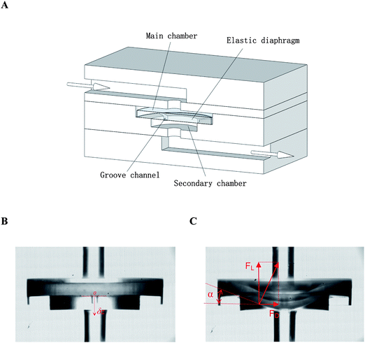
In this work, we designed a microfluidic oscillator through the hydroelasticity approach, which is capable of converting steady laminar flow to oscillatory flow at moderate Re. The design is illustrated in Fig. 1A. It consists of an inlet, outlet, and circular stepped cavity that houses an elastic diaphragm. The upstream and downstream parts of the cavity are labeled here as main chamber and secondary chamber. In between there is a stair, some small grooves are evenly and circumferentially distributed on its surface. The elastic diaphragm is freely placed in the main chamber and it is supported by the stair. Both the chambers are in a shallow and flat shape: ϕ/d > 4, where ϕ and d are respectively diameter and depth of the chambers. The device was embedded into a chip using 4 layers of PMMA (poly(methyl methacrylate)) substrates. The diaphragm was made of silicone rubber (HT-6240, Rogers Corp.). Micro-milling was used to fabricate the microstructures in each layer. They were then bonded together through thermal bonding (see ESI†, Fig. S1 for more fabrication details). In experiments, a pressure P0 was applied to a pressurized liquid container (Nordson Corp.) to pump liquid through the oscillator device. P0 was controlled by an electronic pressure regulator (ITV1050, SMC Corp.). A measuring cylinder was used to collect the liquid at outlet for calculation of flow rate Q. Thanks to the transparency of PMMA, a high speed video camera (FASTCAM SA5, Photron USA Inc.) was used to record the periodic movement of the diaphragm. The frequency was calculated based on the frame rate, and the diaphragm displacement was measured by the pixel numbers.
 | ||
| Fig. 1 Hydroelasticity-based microfluidic oscillator. (A) Schematic illustration of the device architecture. An elastic diaphragm is embedded inside a stepped cavity, perpendicular to the fluid channel. (B) Natural status of the diaphragm without a flow (P0 = 0). (C) Under the pressure of incoming flow, the diaphragm deflects downstream, altering the angle of attack (α), hydrodynamic drag (FD) and lift (FL) forces. | ||
The working principle of the device is interpreted as follows: the liquid entering the main chamber changes its direction and flows radically towards the chamber wall. Then it flows over the edge and bottom surface of the diaphragm, and enters the secondary chamber. The grooves help to prevent blockage of the conduit. In the natural state without flows, the diaphragm remains flat (Fig. 1B). When pressure P0 is applied to drive liquid through the device, the elastic diaphragm will deflect and become convex downstream. The angle of attack (α in Fig. 1C) increases, changing the hydrodynamic drag (FD) and lift forces (FL). As the structure is symmetrical, FD is neutralized and only FL affects the flow. Deflection of the diaphragm also leads to elastic forces which tend to force it to restore the original shape. Here, the gravity is negligible as the device is independent of the orientation according to our test. At low pressures, all these forces reach the equilibrium and the flow is stable. If P0 is increased, the diaphragm will deflect further downstream to reach a new balance. But once P0 exceeds a threshold pressure PI, this balance will be broken down. When the diaphragm is pushed downstream, the inertial force will carry it pass the balancing point, reaching an overshoot state. Next, the elastic and lift forces will push the diaphragm back, and similarly an inertial overshoot occurs. Then, the diaphragm deflects downstream again under incoming flow. As this process repeats itself, oscillation is produced along with periodic movement of the diaphragm, store and release of elastic energy.
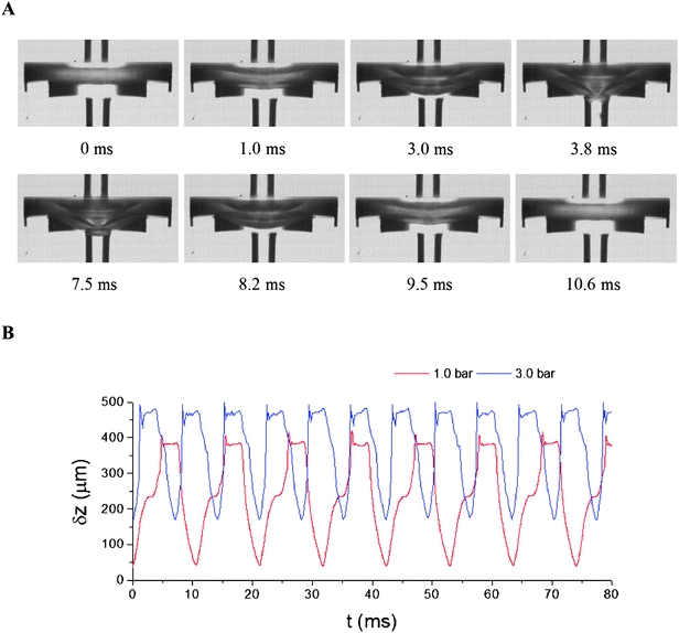
As an example, Fig. 2A presents one typical oscillation cycle (ESI†, Movie S1). At P0 = 1.0 bar, the diaphragm starts to deflect downstream at t = 0 ms, and reaches its maximum position after 3.8 ms. A part of the diaphragm is squeezed into the outlet passage. Then, for the following 3.7 ms (3.8 to 7.5 ms), the diaphragm stays near the bottom of the secondary chamber. Minor vibrations are observed during this stage. After that, it rebounds back to the original position at t = 10.6 ms. Periodic displacement of the diaphragm (δz) is plotted in Fig. 2B. When P0 is increased from 1.0 to 3.0 bar, both δz and the oscillation frequency f are increased (ESI†, Movie S2).
 | ||
| Fig. 2 Oscillation of the diaphragm. Device details are as follows. Diameter and depth of the main chamber: ϕmc = 3000, dmc = 409; for the secondary chamber: ϕsc = 1800, dsc = 304; diameter and thickness of the diaphragm (silicone rubber): ϕdp = 2800, tdp = 250; width and depth of the groove channels: wgv = 150, dgv = 176; diameter of inlet and outlet: ϕin/out = 500 (unit: μm). (A) Snapshots of one oscillation cycle at P0 = 1.0 bar. (B) Diaphragm displacement at 1.0 and 3.0 bar. The coordinate δz points downstream with its origin at the centre of the bottom surface of the diaphragm at P0 = 0 bar (see Fig. 1B). | ||
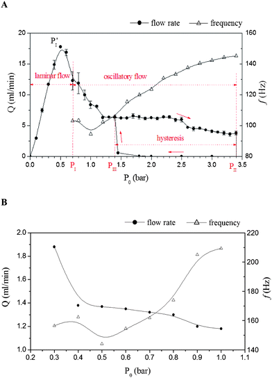
From Fig. 3A, it exhibits striking nonlinearity in the flow resistance (R = P0/Q). Flow rate Q (Q measures the averaged flow rate in the oscillation stage) initially increases with P0. After reaching a maximum value at pressure PI′ (∼0.5 bar), it decreases afterwards. For the differential flow resistance Rdf (=dP0/dQ), PI′ is a critical point across which Rdf changes its sign from positive to negative. Positive Rdf indicates a stable system and the energy input will be dissipated. For negative Rdf, any small perturbation in Q will be magnified to trigger the oscillation. Theoretically, this should be the transition point from stable laminar flow to oscillatory flow. In the testing, the initiation pressure PI is ∼0.7 bar, slightly behind PI′. The delay is believed to relate to the damping effects of the channel. At P0 ≈ 0.7–0.9 bar, the oscillation is not very stable as large variations in Q are observed. With a further increase in P0, the oscillation remains stable in a wide range until a second critical point PII (∼3.4 bar) is reached, beyond which the diaphragm blocks the channel and stops the oscillation. When the pressure is gradually released from the blockage state, hysteresis occurs as the oscillation cannot be restored instantly. This is because in the oscillatory flow state, when the liquid flows over the bottom surface of the diaphragm, it will produce a lift force. The collision of the diaphragm with the bottom surface of the secondary chamber will also produce a force pushing it back. In contrast, both the forces are absent in the steady blockage state. As a result, only at a pressure (PIII) much lower than PII, can the oscillatory flow be restored. For the current case, PIII ≈ 1.4 bar. PI, PII and PIII are critical parameters that determine flow states. The oscillation frequency (f) changes with P0. It is 103.1 Hz at the initiation pressure 0.7 bar. It drops slightly to 94.5 Hz at 1.0 bar and then increases smoothly to 145.3 Hz at 3.4 bar.
 | ||
| Fig. 3 Influence of pressure P0 on flow rate Q and oscillation frequency f. (A) Results of the device as described in Fig. 2. The error bar in Q shows the variation between two measurements. (B) Results of a miniaturized device at sub-millimetre scale. Its dimensions are: ϕmc = 1000, dmc = 226; ϕsc = 600, dsc = 148; ϕin/out = 300. It contains three grooves evenly distributed on the stair surface at 120° separation, wgv = 150, dgv = 86. The diaphragm is latex rubber, ϕdp = 975, tdp = 82 (unit: μm). | ||
Preliminary testing showed that the main operating parameters are determined by the geometry of the device and properties of the elastic diaphragm. For example, reducing the depth of the secondary chamber dsc, increasing the diameter ratio of the two chambers (ϕsc/ϕmc), or using thinner diaphragm will all result in a reduction in the threshold pressure PI. This is because with above changes, R will increase more sharply with P0 due to the rapid deflection of the diaphragm. When its influence on Q exceeds that of the increase in P0, Rdf will become negative. Thus the oscillation starts at a lower pressure. Results also showed that Q increases with the depth of the main chamber dmc. For the oscillation frequency, it is believed to be more related to the natural frequency of the system, and hence the properties of the diaphragm such as Young's modulus, density, etc. However, further investigation is necessary for better understanding.
As the nonlinearity of the flow mainly attributes to the elasticity of the diaphragm, the design is less dependent on the fluid inertial forces. To examine the lower limit of applicable Re, a viscous 50% glycerol–50% water solution is used (see ESI†, Movie S3 as an example), for which the kinetic viscosity (ν) is ∼6.1 × 10⁻⁶ m2 s−1 (at 18.7 °C). For a similar device as tested in Fig. 3A (dmc = 346, dsc = 261, dgv = 168 (μm), other parameters remain the same), the minimum flow rate is obtained to be 1.38 ml min−1 at 1.23 bar. Re (averaged value) is calculated with  , where ū is estimated as the averaged radical velocity flow over the top surface of the diaphragm, ϕdp is the diameter of the diaphragm, v is the kinetic viscosity of the fluid. At Qmin = 1.38 ml min−1,
  . A smaller device at the sub-millimetre scale was further tested. Relevant results are plotted in Fig. 3B. In the operating pressure range from 0.3 to 1.0 bar, Q decreases from 1.88 to 1.18 ml min−1. The corresponding
  is 89.4. The applicable Q and Re range could be further extended through optimization of the geometry of the device, and selection of elastic materials as well.
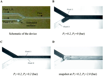
Besides a laminar-to-oscillatory flow converter, the device also works as a check valve. In normal working conditions, when the diaphragm deflects downstream, the groove channels are open allowing the liquid to flow through the device. When pressure is applied in the opposite direction, the diaphragm is forced to attach to the ceiling of the main chamber and block the channel. A similar check valve design and relevant discussions can be found in Truong and Nguyen.22 This additional function can be used for complex flow control. One example is given in Fig. 4. In the Y-shaped fluidic element, an oscillator is embedded in one branch channel. Different pressures, labeled as P1 and P2, are respectively applied to pump fluid 1 and fluid 2. In the test, P1 is fixed at 0.2 bar. Through controlling P2, different flow states can be achieved. (1) At P2 = 0 bar, only fluid 1 can flow through the downstream channel. No flow is observed in the second branch channel, despite the presence of a back pressure. (2) At P2 = 0.2 bar, the valve is open. Both the fluids flow downstream and they remain parallel to each other as the flow is laminar. (3) When P2 is increased to 2.0 bar, it exceeds the threshold pressure PI and falls in the range of oscillatory flow, which leads to sequential segmentation23 and rapid chaotic mixing of the two fluids. Once fluid 2 is released from the side channel, it is instantly mixed with fluid 1 (ESI†, Movie S4).
 | ||
| Fig. 4 Flow control using the oscillator to achieve different flow states. (A) The Y-shaped element used for flow control. Channel width: 500; depth: 400 (μm). (B) At P2 = 0 bar, the oscillator works as a check valve preventing fluid 1 from flowing into the second branch channel. (C) Laminar co-flow of two fluid streams occurs in the pressure range of P1 ≤ P2 < PI. (D) At P2 ≥ PI, oscillatory flow leads to rapid mixing of the liquids. | ||
The influences of elastic hysteresis were observed in the test. The elastic diaphragm will become softer after long time operation, leading to a shift of the operation pressure range towards the lower end. The flow rate is also reduced under same pressure. The influence relates to the dimension of the diaphragm. For silicone rubber of ϕdp = 2.8, tdp = 0.25 (mm), stable oscillation can last 7–8 hours. After that, it becomes more sensitive to external perturbations. As one potential improvement, we are currently examining the feasibility to replace the elastic diaphragm with spring metal foils (e.g., Copper–Beryllium foil).
In summary, we developed a microfluidic oscillator using a hydroelasticity method. Incorporation of elastic materials enhances the nonlinearity of the flow system. As a result, the device is less dependent on the fluid inertial force. The steady to oscillatory flow conversion can be passively realized at moderate Re from 10's to 100. It may be used for high-flow-rate and high-throughput applications. Through controlling upstream pressure of the device, different flow states can be obtained. Oscillatory flow can be used for mixing/heat transfer enhancement,24 chemical process intensification,25,26 fouling reduction and filtration improvement,27etc. It may also be integrated with other fluidic components to gain sophisticated flow control and operation.
Acknowledgements
Thanks to Prof. Ding Hang from University of Science and Technology of China for valuable discussions. The authors gratefully acknowledge the Singapore Institute of Manufacturing Technology, under the Agency for Science, Technology and Research (A*STAR, Singapore) for support of this work.References
- T. M. Squires and S. R. Quake, Rev. Mod. Phys., 2005, 77, 977–1026 CrossRef CAS.
- A. D. Stroock, S. K. W. Dertinger, A. Ajdari, I. Mezic, H. A. Stone and G. M. Whitesides, Science, 2002, 295, 647–651 CrossRef CAS.
- R. H. Liu, M. A. Stremler, K. V. Sharp, M. G. Olsen, J. G. Santiago, R. J. Adrian, H. Aref and D. J. Beebe, J. Microelectromech. Syst., 2000, 9, 190–197 CrossRef.
- X. Mao, J. R. Waldeisen and T. J. Huang, Lab Chip, 2007, 7, 1260–1262 RSC.
- D. Di Carlo, Lab Chip, 2009, 9, 3038–3046 RSC.
- J. P. Brody, T. D. Osborn, F. K. Forster and P. Yager, Sens. Actuators, A, 1996, 54, 704–708 CrossRef.
- S. M. Langelier, D. S. Chang, R. I. Zeitoun and M. A. Burns, Proc. Natl. Acad. Sci. U. S. A., 2009, 106, 12617–12622 CrossRef CAS.
- F. Fahrni, M. W. J. Prins and L. J. van IJzendoorn, Lab Chip, 2009, 9, 3413–3421 RSC.
- H. Aref, J. Fluid Mech., 1984, 143, 1–21 CrossRef.
- H. M. Xia, S. Y. M. Wan, C. Shu and Y. T. Chew, Lab Chip, 2005, 5, 748–755 RSC.
- A. Groisman and V. Steinberg, Nature, 2000, 405, 53–55 CrossRef CAS.
- A. Groisman, M. Enzelberger and S. R. Quake, Science, 2003, 300, 955–958 CrossRef CAS.
- A. Groisman and V. Steinberg, Nature, 2001, 410, 905–908 CrossRef CAS.
- J. A. Pathak, D. Ross and K. B. Migler, Phys. Fluids, 2004, 16, 4028–4034 CrossRef CAS.
- D. J. Beebe, J. S. Moore, J. M. Bauer, Q. Yu, R. H. Liu, C. Devadoss and B.-H. Jo, Nature, 2000, 404, 588–590 CrossRef CAS.
- J. T. Yang, C. K. Chen, I. C. Hu and P. C. Lyu, J. Microelectromech. Syst., 2007, 16, 826–835 CrossRef.
- V. Tesar, Chem. Eng. J., 2009, 155, 789–799 CrossRef CAS.
- M. A. Unger, H.-P. Chou, T. Thorsen, A. Scherer and S. R. Quake, Science, 2000, 288, 113–116 CrossRef CAS.
- T. Thorsen, S. J. Maerkl and S. R. Quake, Science, 2002, 298, 580–584 CrossRef CAS.
- D. C. Leslie, C. J. Easley, E. Seker, J. M. Karlinsey, M. Utz, M. R. Begley and J. P. Landers, Nat. Phys., 2009, 5, 231–235 CrossRef CAS.
- B. Mosadegh, C.-H. Kuo, Y.-C. Tung, Y.-S. Torisawa, T. Bersano-Begey, H. Tavana and S. Takayama, Nat. Phys., 2010, 6, 433–437 CrossRef CAS.
- T. Q. Truong and N. T. Nguyen, J. Micromech. Microeng., 2004, 14, 632–638 CrossRef CAS.
- N. T. Nguyen and X. Y. Huang, Lab Chip, 2005, 5, 1320–1326 RSC.
- E. M. Benavides, J. Appl. Phys., 2009, 105, 094907 CrossRef.
- A. N. Phan, A. Harvey and J. Lavender, Chem. Eng. Process., 2011, 50, 254–263 CrossRef CAS.
- M. Z. Zheng and M. R. Mackley, Chem. Eng. Sci., 2008, 63, 1788–1799 CrossRef CAS.
- B. Olayiwola and P. Walzel, J. Membr. Sci., 2009, 345, 36–46 CrossRef CAS.
Footnote |
| † Electronic supplementary information (ESI) available. See DOI: 10.1039/c1lc20667b |
| This journal is © The Royal Society of Chemistry 2012 |
