Long term cycling studies of electrospun TiO2 nanostructures and their composites with MWCNTs for rechargeable Li-ion batteries†
Peining
Zhu‡
ab,
Yongzhi
Wu‡
bcd,
M. V.
Reddy
*d,
A.
Sreekumaran Nair
*b,
B. V. R.
Chowdari
d and
S.
Ramakrishna
abce
aDepartment of Mechanical Engineering, National University of Singapore, Singapore, 117574
bHealthcare and Energy Materials Laboratory, Nanoscience and Nanotechnology Initiative, National University of Singapore, Singapore, 117581
cNUS Graduate School for Integrative Sciences and Engineering, Singapore, 117456
dDepartment of Physics, National University of Singapore, Singapore, 117542. E-mail: phymvvr@nus.edu.sg (M. V. Reddy), nniansn@nus.edu.sg (A. S. Nair)
eKing Saud University, Riyadh, 11451, Kingdom of Saudi Arabia
First published on 11th November 2011
Abstract
Nanofiber- and rice grain-shaped TiO2 nanostructures and their composites with functionalized multiwalled carbon nanotubes were fabricated by electrospinning and subsequent sintering process for applications in Lithium ion batteries. The fabricated nanostructures were characterized by X-ray diffraction, Raman spectroscopy, X-ray photoelectron spectroscopy, scanning-and transmission electron microscopy and surface area measurements. All nanostructured materials showed average discharge-charge plateaux of 1.75 to 1.95V. The nanofibrous- and rice grain-shaped TiO2 nanomaterials showed stable performances of 136 (± 3) mAh g−1 and 140 (± 3) mAh g−1, respectively, at the end of 800 cycles in the cycling range of 1.0–2.8 V vs.Li at a current rate of 150 mA g−1. TiO2–CNT (4 wt.%) composites showed a slightly lower capacity value but better capacity retention (8% capacity loss between 10–800 cycles). We believe that the present long term cycling materials would have wide interests in lithium ion batteries research.
Introduction
Electrospinning, as a very simple and convenient means to mass fabricate one-dimensional (1-D)/anisotropic nanostructures has been widely researched and utilized to fabricate advanced functional materials such as nanofibers of polymers,1 metal oxides,2 and composites.3 Electrospun materials find widespread applications in different fields such as photovoltaics,4,5 energy storage,6,7water treatment,8 regenerative medicine9–11, etc. Compared to other fabrication methods for 1-D nanostructures, electrospinning has several advantages such as a simple setup comprising a spinneret with a polymeric precursor, a high voltage power supply and a collector, low cost, and feasibility for mass production. With proper selection of polymer, solvent, and other experimental parameters such as working distance and applied voltage, the morphology and hence the properties of the electrospun materials can be easily controlled.12,13 For the above reasons, a large number of metal oxides with desired 1-D nanostructures have been synthesized by electrospinning.6,7,14,15Titanium dioxide (TiO2) is one of the candidates for anode materials in lithium-ion batteries (LIBs) in view of its properties such as low cost, environmental friendliness,16–18 and higher Li-insertion potential (1.5–1.8 V vs. Li+/Li) than the commercialized carbon anode materials.19,20 However, the low electronic conductivity of TiO2 limits its applications in LIBs.16,21,22 To solve this problem and increase the Li-cycling performance of TiO2, many approaches have been considered including the fabrication of one dimensional nanostructures and TiO2/carbon composites. One-dimensional TiO2 nanostructures such as nanowires,23nanotubes,19 and nanoribbons,24 have been reported to demonstrate good performance owing to higher electrode/electrolyte contact area and shorter transport path lengths for electrons and Li ions and are considered as promising anode materials. The carbon/TiO2 composites have also been reported with enhanced electrochemical performance.25,26
In our previous work, we have utilized the electrospinning technique to fabricate 1-D TiO2 nanofibers, rice grain shaped nanomaterials, and their composites with carbon nanotubes. The TiO2 nanostructures showed good performance in photocatalysis and dye-sensitized solar cells.27–29 The present paper explores the utility of the TiO2 nanofibers and rice grain-shaped TiO2 and their composites with CNTs as the anode materials for the LIBs. The rice grain- and fiber-shaped TiO2 nanostructures showed long term stable performances of 140 mAh g−1 and 136 mAh g−1, respectively, in the cycling range of 1.0–2.8 V vs.Li and the stable performance remains even after 800 cycles, at a current rate of 150 mA g−1. The TiO2–CNT (4 wt.%) composites showed a slightly lower capacity value but better capacity retention (8% capacity fade between 10–800 cycles).
Experimental
a. Materials
Titanium isopropoxide (TIP, 97%), N,N-dimethyl acetamide (DMAc, 99.8%), polyvinylpyrrolidone (PVP, Mn = 10![[thin space (1/6-em)]](https://www.rsc.org/images/entities/char_2009.gif) 000), and polyvinyl acetate (PVAc, Mn = 500000) were purchased from Aldrich. Multiwalled carbon nanotubes (MWCNTs, purity >98%, outer diameter between 10 to 20 nm and length between 1 to 2 μm) were purchased from Shenzhen (China). Acetic acid (99.7%) was from LAB-SCAN Analytical Sciences, Thailand. Methanol (CHROMASOLV, Aldrich), ethanol (absolute, Fischer scientific, Leicestershire, UK), acetone (AR grade, Fisher Scientific, UK), lithium hexafluorophosphate (99%, Merck), 1 M LiPF6, ethylene carbonate (EC), diethyl carbonate (DEC) (Merck) (1:1 by volume), carbon black (Super P carbon, Merck), polyvinylidene fluoride copolymer (Kynar 2801), N-methyl 2-pyrrolidinone (Alfa asesar), Lithium metal foil (Kyokuto metal Co., Japan) and glass microfiber filter membrane (Whatmen Aldrich) were used as received.
000), and polyvinyl acetate (PVAc, Mn = 500000) were purchased from Aldrich. Multiwalled carbon nanotubes (MWCNTs, purity >98%, outer diameter between 10 to 20 nm and length between 1 to 2 μm) were purchased from Shenzhen (China). Acetic acid (99.7%) was from LAB-SCAN Analytical Sciences, Thailand. Methanol (CHROMASOLV, Aldrich), ethanol (absolute, Fischer scientific, Leicestershire, UK), acetone (AR grade, Fisher Scientific, UK), lithium hexafluorophosphate (99%, Merck), 1 M LiPF6, ethylene carbonate (EC), diethyl carbonate (DEC) (Merck) (1:1 by volume), carbon black (Super P carbon, Merck), polyvinylidene fluoride copolymer (Kynar 2801), N-methyl 2-pyrrolidinone (Alfa asesar), Lithium metal foil (Kyokuto metal Co., Japan) and glass microfiber filter membrane (Whatmen Aldrich) were used as received.
b. Fabrication of rice grain-shaped TiO2 and TiO2-MWCNT composites
The electrospinning solution was prepared from PVAc, DMAc, acetic acid, TIP and –COOH functionalized CNTs using a typical procedure previously reported.30 Briefly, taking TiO2–CNT (4 wt.%) as an example, 5 mg –COOH functionalized CNTs was dispersed in 10 mL DMAc by sonication for 3 h. The PVAc (1.2 g) was then added into the solution with stirring. After stirring for 15 min, 2 mL of glacial acetic acid and 1 mL of TIP respectively, were added. The solution was kept under stirring for 12 h when the dark viscous solution became homogeneous. The solutions were then subjected to electrospinning using a commercial machine (NANON, MECC Japan) with an applied voltage of 25 kV, working distance of 14 cm and a flow rate of 1.5 mL h−1. The humidity level inside the electrospinning chamber was maintained at around 50%. The electrospun fibers were collected on an aluminum foil wrapped around a rotating drum collector. The deposited fibers were removed in the form of a freestanding sheet after five batches of polymeric solutions were electrospun and were sintered at 450 °C for 1 h in air with a heating rate of 2 °C min−1 to get the rice grain-shaped composites.30,31 Solutions without CNTs were also electrospun under the same conditions to obtain rice grain-shaped TiO2 nanostructures.c. Fabrication of TiO2 nanofibers
TiO2 nanofibers were fabricated according to literature reports.32 First, 0.6 g polyvinylpyrrolidone (PVP) was dissolved in 7 mL ethanol. Two millilitre each of acetic acid TIP were added into the as-prepared solution. After stirring for 1 h, the solution was electrospun at an applied voltage of 20 kV, a flow rate of 1.5 mL h−1 and a working distance of 15 cm. After 5 batches of solutions were electrospun, the obtained composite fibers were removed and annealed at 500 °C for 1 h in air to obtain the TiO2 nanofibers.d. Fabrication of lithium ion batteries
Electrochemical performance was studied using electrospun TiO2 nanomaterials as working electrode together with carbon black and binder (Kynar 2801) keeping their weight ratio at 70:15:15. The Li-metal foil was utilized as the counter-and the reference electrodes. The polyvinylidene fluoride copolymer (Kynar 2801) dissolved in N-methyl-2-pyrrolidinone was used as the solvent to disperse the TiO2/TiO2–CNT nanostructures, carbon black. The viscous slurry was coated on an etched Cu-foil (as a current collector) by doctor blade technique. The geometrical area of the electrode was 2.0 cm2 with a thickness of ∼10 μm. Electrolyte was fabricated by dissolving 1M LiPF6 in a 1:1 (v/v) mixture of ethylene carbonate and diethyl carbonate. Glass microfibre filter membrane was the separator. Coin-type test cells (CR2016) were fabricated in an Ar-gas filled glove box. More details on cell fabrication can be found in our previous papers.33–36
e. Characterization and measurements
The morphology of the electrospun nanomaterials was investigated by scanning electron microscopy (SEM) (Quanta 200 FEG operated at 5∼15 kV and JEOL JSM-6701F operated at 5∼15 kV, respectively). The morphology/structure was investigated by transmission electron microscopy (TEM, JEOL 3010, operated at 300 kV). The X-ray diffraction (XRD) patterns were recorded using a Philips X'pert unit with Cu-Kα radiation (1.54 Å). The Brunauer-Emmett-Teller (BET) surface area measurements were carried out using a Micromeritics (USA). Discharge–charge cycling was carried out using a bitrode battery tester (Model SCN, USA) and further details on the instrumentation are reported previously.37Results and discussion
a. Structure and morphology
Fig. 1(a) and 1(b) show the SEM images of the rice grain-shaped TiO2 nanostructures in low and high magnifications, respectively. From the SEM images, we can see a well connected TiO2 network with uniform rice grain-shaped nanostructures. The average dimensions of the TiO2 nanostructures were 450 nm in length and 150 nm in diameter. Fig. 1(c) shows the SEM image of the composite electrode made of the TiO2, the carbon black and the PVDF, revealing well-dispersion of the TiO2 nanostructures in the carbon black matrix.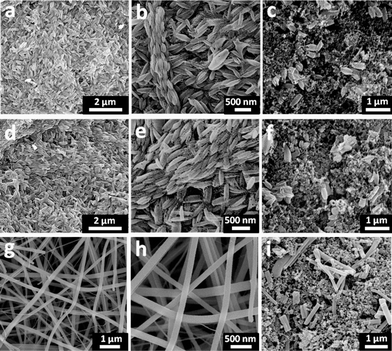 | ||
| Fig. 1 SEM images of electrospun rice grain shaped-TiO2nanostructures in low (a) and high (b) magnifications, rice grain shaped TiO2–CNT (4 wt.%) nanostructures in low (d) and high (e) magnifications, and TiO2 nanofibers in low (g) and high (h) magnifications. SEM images of the composite electrodes made of carbon black, PVDF, and the rice grain-shaped TiO2 nanostructures (c), rice grain-shaped TiO2–CNT (4 wt.%) nanostructures (f), and TiO2 nanofibers (i). | ||
Similarly, Fig. 1(d) and (e) show the rice grain-shaped morphology for the electrospun TiO2–CNT (4 wt.%) nanocomposites. From the SEM images; it is clear that the composite has the same rice grain morphology. The average dimensions of the nanostructures were nearly the same as that for the bare TiO2. At such low loadings, the CNTs were not visible in the SEM images; however, the presence of CNTs was confirmed by TEM (see below), Raman, and X-ray photoelectron spectroscopy, respectively (see supporting information SI 1–2 also†). The signatures of C1s peak in XPS (SI 1) and the peaks of CNTs in the Raman spectrum (SI 2) of the composite demonstrate the presence of CNTs into the TiO2 network. The SEM image of the TiO2–CNT, carbon black composite electrode is also shown in Fig. 1(f). Fig. 1(g) and 1(h) show the SEM images of the electrospun TiO2 nanofibers showing their typical continuous nature. The average diameter of the fibers was 150 nm. Due to the grinding process employed for the slurry preparation, the continuous nanofibers break into nanorods and were dispersed into the carbon black and polymer matrix as shown in the Fig. 1(i).
The rice grain shaped TiO2 and TiO2–CNT nanostructures were further investigated by the high-resolution transmission electron microscopy (HR-TEM). Fig. 2(a) and 2(d), respectively, show the TEM images of pure TiO2 and TiO2–CNT nanocomposite, showing the rice grain morphology for both. It is clear from the TEM images that each rice grain-shaped TiO2 is made of spherical/elliptical nanoparticles with an average diameter of 20 nm and most of the rice grain nanostructures were also hollow. In the case of TiO2–CNT composite, CNTs were seen sticking out of the nanostructures thus demonstrating the formation of composites between the two, which is needed to improve the electronic conductivity of TiO2. The lattice-resolved images and the selected area electron diffraction (SAED) patterns of both TiO2 and TiO2–CNT nanocomposite shown in Fig. 2(b), 2(c), 2(e) and 2(f) indicate that the rice grain-shaped TiO2 nanostructures were single crystalline anatase phase.
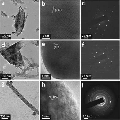 | ||
| Fig. 2 TEM images: (a) high resolution TEM image; scale bar, 100 nm, (b) high resolution lattice resolved image; scale bar, 5 nm, and (c) SAED pattern of electrospun rice grain shaped-TiO2nanostructures. (d) High resolution TEM image; scale bar, 100 nm, (e) high resolution lattice resolved image; scale bar, 5 nm, and (f) SAED pattern of electrospun rice grain shaped-TiO2–CNT (4 wt.%) nanocomposite. (g) High resolution TEM image; scale bar, 200 nm, (h) high resolution lattice resolved image; scale bar, 5 nm, and (i) SAED pattern of a bare electrospun TiO2 nanofiber. | ||
Fig. 2(g) shows the TEM image of a single TiO2 nanofiber, indicating the smooth surface and an average diameter of 140 nm. Fig. 2(h) and 2(i) show the lattice-resolved image and the SAED pattern, revealing the anatase phase and the polycrystalline nature of the TiO2 nanofibers, respectively.
Crystal structure of the rice grain shaped TiO2 was further investigated by XRD. The respective XRD pattern is shown in Fig. 3 and is indexed (hkl) to pure anatase phase. The anatase phase of TiO2 was retained in the composite case. However, for the TiO2–CNT composites, no peak of CNT was identified, for the overlap of the 002 peak of CNT with the 101 peak of anatase38 and also due to its low concentration. The lattice parameters of the TiO2 nanostructures were a/Å = 3.787 and c/Å = 9.503. The average crystallite size (Lorentzian) was 20 (± 2) nm; similar to the results determined form the TEM images. For the TiO2–CNT composites, the lattice parameters and the crystallite sizes remained the same. The Fig. 3(d) shows the XRD pattern of the TiO2 nanofibers, indicating the existence of both anatase (87.7%) and rutile phases (12.3%) (Table 1). The lattice parameters for the TiO2 nanofibers were a/Å = 3.787; c/Å = 9.504 for anatase and a/Å = 4.594; c/Å = 2.598 for rutile. The crystallite size in TiO2 nanofibers was 18 (± 2) nm for anatase and 19 (± 2) nm for rutile, which was similar to the size determined from the TEM measurements. More details on the Rietveld parameters and particle sizes were presented in Table 1. The BET values were in the range of 34–39 m2 g−1 (Table 1).
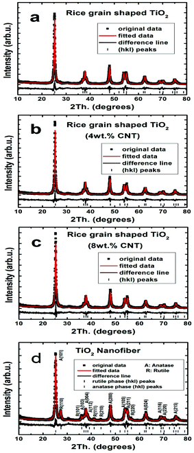 | ||
| Fig. 3 X-ray diffraction patterns of rice grain-shaped TiO2 nanostructures (a), TiO2–CNT (4 wt.%) nanocomposite (b), TiO2–CNT (8 wt.%) nanocomposite (c), and TiO2 nanofibers (d). | ||
| Compound | Lattice Parameter | Rietveld parameters (%) | BET surface area (± 0.2) (m2 g−1) | Crystallite size ((± 2) nm) | ||
|---|---|---|---|---|---|---|
| TiO2 rice grains | a/Å = 3.787(7) | R-Bragg = 3.4 | Rexp. = 13.9 | 34.1 | 20 | |
| Rwp = 18.7 | ||||||
| c/Å = 9.503(4) | Rp = 13.9 | |||||
| GOF = 1.3 | ||||||
| TiO2 rice grains (4wt.% CNT) | a/Å = 3.789(2) | R-Bragg = 3.2 | Rexp = 13.9 | 34.2 | 21 | |
| Rwp = 19.6 | ||||||
| c/Å = 9.504(3) | Rp = 14.2 | |||||
| GOF = 1.4 | ||||||
| TiO2 rice grains (8wt.% CNT) | a/Å = 3.789(7) | R-Bragg = 3.4 | Rexp. = 14.1 | 38.6 | 20 | |
| Rwp = 19.5 | ||||||
| c/Å = 9.504(3) | Rp = 14.3 | |||||
| GOF = 1.4 | ||||||
| TiO2 nanofiber | Anatase 88% | a/Å = 3.787(9) | R-Bragg = 2.9 | Rexp. = 14.3 | 37.2 | 18 |
| c/Å = 9.504(0) | Rwp = 18.7 | |||||
| Rutile 12% | a/Å = 4.594(1) | R-Bragg = 5.7 | Rp = 13.8 | 19 | ||
| c/Å = 2.958(9) | GOF = 1.3 | |||||
b. Galvanostatic cycling
Galvanostatic discharge-charge cycling and capacity vs. cycle number (n) plots of rice grain-shaped TiO2 nanostructures, TiO2–CNT nanocomposites and the TiO2 nanofibers are shown in Fig. 4 and Fig. 5, at a current density of 150 mA g−1 (0.45C rate, assuming 1C = 335 mA g−1) and potential range of 1.0–2.8 V vs.Li. We note Chen et al.39,40 defined 1C = 167.5 mA g−1 and Reddy et al.,33 Dambournet et al.,41 Sarvanan et al.42 assumed 1C =335 mA g−1. In many reports in the literature it is demonstrated that in the case of nanostructured TiO2 at low current is possible to react 1 mole of lithium per mole of TiO2. In a similar case with the cathode LiFePO443 many reports showed one Li can be removed from the host compound, where it is assumed a C-rate based on the theoretical capacity (1C = 170 mA g−1). Other electrode materials namely, LiCoO244, bare and doped-LiMn2O445,46,47 and Li(Ni1/3Co1/3Mn1/3)O2,48LiVPO4F,49 (V1/2Sb1/2Sn)O4,50Co3O451 and CoN52 assumed and defined the C-rate based on the operating voltage and reversible capacity. In the present work, for clarity, we fixed 1C = 335 mA g−1 based on the well known equation TiO2+xLi+xe−→LixTiO2 (x = 1). We can also define the C-rate based on the reversible capacity of TiO2.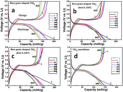 | ||
| Fig. 4 Galvanostatic discharge-charge cycling curves (voltage vs. capacity profiles) of rice grain shaped TiO2, TiO2–CNT nanostructures, and TiO2 nanofibers. Current rate: 150 mA g−1 (0.45 C rate; assumed 1 C = 333 mA g−1). Li metal was the counter and reference electrodes. Potential window: 1.0–2.8 V. Number implies the cycle number. | ||
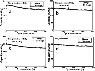 | ||
| Fig. 5 Capacity vs. cycle number of (a) rice grain shaped TiO2, (b,c) 4 and 8wt.% TiO2–CNT nanostructures, and (d) TiO2 nanofibers. Current rate: 150 mA g−1 (0.45 C rate). Li metal was the counter and reference electrode. Potential window: 1.0–2.8 V. | ||
During discharge and charge cycles all compounds (at the end of 100th cycle) show flat potentials at 1.75 and 1.95 V vs.Li. These flat potentials are similar to reported results.33,53–55 For the rice grain-shaped TiO2 nanostructures, the specific capacities during the first discharge and charge cycles were 207 and 162 (± 3) mAh g−1, respectively, which correspond to 0.62 and 0.48 moles of lithium per mole of TiO2 during discharge-charge cycle. The specific capacities for TiO2 nanofibers during the first discharge and charge cycle were lower, i.e., 187 and 144 (± 3) mAh g−1, respectively, which correspond to 0.56 and 0.43 moles of lithium per mole of TiO2 during discharge-charge cycle. The relatively lower discharge-charge capacity of TiO2 nanofibers is most likely due to the presence of rutile phase and differences in the morphologies and the crystal structure compared to that of rice grain-shaped nanostructures. The presence of anatase and rutile phases in TiO2 nanofibers would result in more grain boundaries which would decrease the conductivity and the diffusion of Li ions and further studies are needed to explain above observations.
Interestingly, both the TiO2 nanofibers and rice grain-shaped nanostructures showed long term stable cycling performance. From 10 to 500 cycles, the discharge capacity of TiO2 rice grain nanostructures decreased from 173 to 146 mAh g−1, corresponding to 15% capacity fading (Table 2). Moreover, after 800 cycles, the capacity remained at 140 mAh g−1, demonstrating high performance of 81% retention of the capacity from 10–800 cycles. TiO2 nanofibers also showed stable cycling performance. Form 10–500 cycles, the discharge capacity of nanofibers decreased from 148 to 138 mAh g−1, which is only a 7% capacity fading. The capacity remained at 136 mAh g−1 after 800 cycles, which is a 92% retention of the capacity at 10 cycles. The results demonstrate that the rice grain nanostructures and nanofibers acted as anode materials with a stable performance for Li ion batteries. The details of the capacity values from 1 to 800 cycles are presented in Table 2.
| Compound name | 1st discharge capacity ((± 3) mAh g−1) | 1st charge capacity ((± 3) mAh g−1) | 10th discharge capacity ((± 3) mAh g−1) | 500th discharge capacity ((± 3) mAh g−1) | 800th discharge capacity ((± 3) mAh g−1) | Capacity fading |
|---|---|---|---|---|---|---|
| TiO2 - Rice grain; (150 mA g−1) | 207 | 162 | 173 | 146 | 140 | 15% (10–500 cyc.) 19.0% (10–800 cyc) |
| TiO2 - nanofibers (150 mA g−1) | 187 | 144 | 148 | 138 | 136 | 7% (10–500 cyc) 8.5% (10–800 cyc.) |
| TiO2–CNT (4 wt.%) (150 mA g−1) | 179 | 139 | 149 | 139 | 136 | 7% (10–500 cyc.) 8% (10–800 cyc.) |
| TiO2–CNT (8 wt.%) (150 mA g−1) | 208 | 151 | 153 | 129 | 129 | 15% (10–500 cyc.) 16% (10–800 cyc.) |
The reasons for the good capacity retention for electrospun nanofibers and rice grain nanostructures could be: 1) the one-dimension nanostructured TiO2 nanofibers as well as the rice grain-shaped one would shorten the path lengths for both Li ion and electrons. The high performance of stable capacity could be attributed to the mixed conducting 3-D networks formed by the porous electrospun materials with relatively larger dimension and the conducting carbon black, as revealed by the SEM images (Fig. 1c, f, i). A schematic illustration of the same is shown in Fig. 6a, b. The porous structure of the electrospun materials would be beneficial for the stable performance. Due to the evaporation of the polymers during sintering process, the electrospun nanofibers as well as the rice grain-shaped nanostructures became porous, which would help the de-intercalation/intercalation of lithium during the cycling process.33
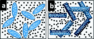 | ||
| Fig. 6 Schematic illustration of the conducting 3 D networks of carbon black with rice grain shaped-TiO2nanostructures (a) and TiO2 nanofibers (b). | ||
The voltage vs. capacity profiles of TiO2–CNT composites are shown in Fig. 4b and 4c with similar discharge-charge plateaus of bare TiO2 nanostructures and slightly lower polarization. At the same time, we noticed that the capacity fading was decreased for the TiO2–CNT composite. The capacity fading for TiO2–CNT (4 wt.%) nanocomposite from 10 to 500 cycles was 6.8% which is less than half of that of pure rice grain-shaped TiO2 nanostructures. After 800 cycles, the capacity fading of the composite was 8%, which showed better capacity retention than the bare TiO2 (19% capacity loss) (Table 2). For the high electronic conductivity, CNTs in the TiO2 nanostructures would provide fast transport channels for the electrons and decrease the volume variation, which would increase the structural stability of the electrodes and then enhance the capacity retention during cycling.56,57 It should be noted that, even without CNTs incorporation, the TiO2 nanofibers showed a high stable performance which is only slightly lower than that of the retention of the TiO2–CNT (4 wt.%) composite. It is reasonable to expect a higher retention for the TiO2–CNT composite nanofibers. However, due to technical problems we failed to fabricate the same, as the introduction of CNTs into the PVP-ethanol solution caused frequent blocking of the needles during the electrospinning process. At the same time, we have found that a still further increase in the concentration of CNTs (i.e. 8 wt.%) would increase the capacity fading. The reason could be that the extra CNTs in the TiO2 matrix would decrease the efficient process of the de-intercalation/intercalation on the surface of TiO2 due to less electroactive element. To verify the capacity contribution due to MWCNTs, we performed electrochemical studies (SI-3) in the cycling range of 1.0–2.8 V vs.Li at current rate of 40 mA g−1, which showed a reversible capacity of ∼10 mAh g−1 and at high current of 150 mA g−1, the capacity contribution due to CNTs was around 0.8 mAh g−1. Thus the lower capacity of the composites compared to the rice grain-shaped TiO2 could be due to lesser active material participation in electrochemical cycling (SI-3)†. The overall observed reversible capacity is slightly higher than that of bare- and Ag- and Au-coated TiO2 nanofibers,58 our previous studies,33 and TiO2 nanoparticles.59 We are not able to compare our long term capacity fading values with literature reports, as to the best of our knowledge; there were not many reports on cycling up to 800 cycles at a current rate 150 mA g−1. The probable reasons for the differences in the electrochemical properties could be the differences in the preparation methods and reaction conditions like temperature and initial reactants which will influence the morphology, crystal structure, surface area and electrochemical properties and other factors like fabrication technology and active material loading and differences in the geometrical area of the electrode.
We further investigated the rate capacities of all the samples. The capacity vs. cycle number profiles are presented in Fig. 7 and the galvanostatic discharge-charge cycling curves of all the samples at different current rates are provided in Fig. 8, which are in agreement with the results discussed above (Fig. 5) and a slight differences in the hystereses between charge-discharge cycles are clearly seen with different current rates (Fig. 8). As shown in Fig. 7, the rice grain-shaped TiO2 showed the highest capacity of 171 mAh g−1, while the TiO2/CNT (4 wt.%), TiO2–CNT (8 wt.%), and TiO2 nanofibers respectively showed relatively lower capacity of 150 mAh g−1, 150 mAh g−1, and 145 mAh g−1 at the current rate of 0.45 C and the end of 8th cycle. During the rate performance, the TiO2–CNT composite showed a better capacity retention when the current eventually increased to high current rate of 4.5 C. The capacities of pure rice grain shaped TiO2 and TiO2 nanofibers reduced to 89 mAh g−1, 73 mAh g−1 at a current rate of 4.5 C (at the end of 8th cycle), which is only 52% and 50% retention of those at the initial stage. The TiO2–CNT (8 wt.%) and TiO2–CNT (4 wt.%) showed the capacities of 85 mAh g−1 and 81 mAh g−1, which are 57% and 54% of the capacities of the initial stage of 0.45 C, indicating the improved rate capacity of TiO2–CNT composite.
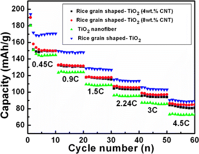 | ||
| Fig. 7 Capacity vs. cycle number plots of bare and TiO2 composites nanostructured materials at different current rates of 150 mA g−1 (0.45 C, assumed 1 C = 333 mA g−1), 300 mA g−1 (0.9 C) , 500 mA g−1 (1.5 C) , 750 mA g−1 (2.24 C) , 1000 mA g−1 (3 C) , and 1500 mA g−1 (4.5 C) . Li metal was the counter and reference electrode. Potential window: 1.0–2.8 V. | ||
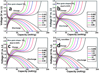 | ||
| Fig. 8 Galvanostatic discharge-charge cycling curves (voltage vs. capacity profiles) of all TiO2 composites materials at different current rates of 150 mA g−1 (0.45 C), 300 mA g−1 (0.9 C) , 500 mA g−1 (1.5 C) , 750 mAg−1 (2.24 C) , 1000 mAg−1 (3 C) , and 1500 mAg−1 (4.5 C) (assume 1C = 333 mA g−1). Li metal was the counter and reference electrode. Potential window: 1.0–2.8 V. For clarity 8th discharge–charge cycle are shown. | ||
Conclusions
In conclusion, we have fabricated 1 D electrospun materials of TiO2 nanofibers and rice grain shaped TiO2 and TiO2–CNT nanocomposites by the electrospinning method. The obtained materials showed a long term cycling stability and a stable performance up to 800 cycles, with capacity retention of 92% (10 to 800 cyc.) and 81% (10 to 800 cyc.) for TiO2 nanofibers and TiO2 rice grain nanostructures, respectively. At the same time, the TiO2–CNT rice grain-like composite nanostructures showed enhancement in the capacity retention (10 to 800 cyc.) by increasing the retention from 81% to 92%. We believe the as-prepared materials would have good applications in stable lithium ion batteries.References
- Z. Sun, E. Zussman, A. L. Yarin, J. H. Wendorff and A. Greiner, Adv. Mater., 2003, 15, 1929 CrossRef CAS.
- I. D. Kim, A. Rothschild, B. H. Lee, D. Y. Kim, S. M. Jo and H. L. Tuller, Nano Lett., 2006, 6, 2009 CrossRef CAS.
- D. Li and Y. Xia, Nano Lett., 2004, 4, 933 CrossRef CAS.
- K. Onozuka, B. Ding, Y. Tsuge, T. Naka, M. Yamazaki, S. Sugi, S. Ohno, M. Yoshikawa and S. Shiratori, Nanotechnology, 2006, 17, 1026 CrossRef CAS.
- H. S. Shim, S. I. Na, S. H. Nam, H. J. Ahn, H. J. Kim, D. Y. Kim and W. B. Kim, Appl. Phys. Lett., 2008, 92, 183107 CrossRef.
- A. L. Viet, M. V. Reddy, R. Jose, B. Chowdari and S. Ramakrishna, J. Phys. Chem. C, 2009, 114, 664 Search PubMed.
- Z. Dong, S. J. Kennedy and Y. Wu, J. Power Sources, 2011, 196, 4886 CrossRef CAS.
- R. Gopal, S. Kaur, Z. Ma, C. Chan, S. Ramakrishna and T. Matsuura, J. Membr. Sci., 2006, 281, 581 CrossRef CAS.
- M. Shin, H. Yoshimoto and J. P. Vacanti, Tissue Eng., 2004, 10, 33 CrossRef CAS.
- Q. P. Pham, U. Sharma and A. G. Mikos, Tissue Eng., 2006, 12, 1197 CrossRef CAS.
- Z. Ma, M. Kotaki, R. Inai and S. Ramakrishna, Tissue Eng., 2005, 11, 101 CrossRef CAS.
- W. Teo and S. Ramakrishna, Nanotechnology, 2006, 17, R89 CrossRef CAS.
- Z. M. Huang, Y. Z. Zhang, M. Kotaki and S. Ramakrishna, Compos. Sci. Technol., 2003, 63, 2223 CrossRef CAS.
- D. Li, J. T. McCann, Y. Xia and M. Marquez, J. Am. Ceram. Soc., 2006, 89, 1861 CrossRef CAS.
- R. Ramaseshan, S. Sundarrajan, R. Jose and S. Ramakrishna, J. Appl. Phys., 2007, 102, 111101 CrossRef.
- B. L. He, B. Dong and H. L. Li, Electrochem. Commun., 2007, 9, 425 CrossRef CAS.
- V. Subramanian, A. Karki, K. Gnanasekar, F. P. Eddy and B. Rambabu, J. Power Sources, 2006, 159, 186 CrossRef CAS.
- M. V.Reddy, G. V. Subba Rao and B. V. R. Chowdari, Chemical Review, 2011 Search PubMed (under revision).
- H. T. Fang, M. Liu, D. W. Wang, T. Sun, D. S. Guan, F. Li, J. Zhou, T. K. Sham and H. M. Cheng, Nanotechnology, 2009, 20, 225701 CrossRef.
- M. A. Reddy, M. S. Kishore, V. Pralong, V. Caignaert, U. Varadaraju and B. Raveau, Electrochem. Commun., 2006, 8, 1299 CrossRef CAS.
- Y. G. Guo, Y. S. Hu, W. Sigle and J. Maier, Adv. Mater., 2007, 19, 2087 CrossRef CAS.
- Z. G. Yang, D. Choi, S. Kerisit, K. M. Rosso, D. H. Wang, J. Zhang, G. Graff and J. Liu, J. Power Sources, 2009, 192, 588 CrossRef CAS.
- H. W. Shim, D. K. Lee, I. S. Cho, K. S. Hong and D. W. Kim, Nanotechnology, 2010, 21, 255706 CrossRef.
- Q. Li, J. Zhang, B. Liu, M. Li, R. Liu, X. Li, H. Ma, S. Yu, L. Wang and Y. Zou, Inorg. Chem., 2008, 47, 9870 CrossRef CAS.
- F. F. Cao, Y. G. Guo, S. F. Zheng, X. L. Wu, L. Y. Jiang, R. R. Bi, L. J. Wan and J. Maier, Chem. Mater., 2010, 22, 1908 CrossRef CAS.
- I. Moriguchi, R. Hidaka, H. Yamada, T. Kudo, H. Murakami and N. Nakashima, Adv. Mater., 2006, 18, 69 CrossRef CAS.
- A. S. Nair, Y. Shengyuan, Z. Peining and S. Ramakrishna, Chem. Commun., 2010, 46, 7421 RSC.
- Y. Shengyuan, Z. Peining, A. S. Nair and S. Ramakrishna, J. Mater. Chem., 2011, 21, 6541 RSC.
- K. Fujihara, A. Kumar, R. Jose, S. Ramakrishna and S. Uchida, Nanotechnology, 2007, 18, 365709 CrossRef.
- Z. Peining, A. S. Nair, Y. Shengyuan and S. Ramakrishna, Mater. Res. Bull., 2010, 46, 588 CrossRef.
- T. Okpalugo, P. Papakonstantinou, H. Murphy, J. Mclaughlin and N. Brown, Carbon, 2005, 43, 2951 CrossRef CAS.
- Y. Shengyuan, A. S. Nair, R. Jose and S. Ramakrishna, Energy Environ. Sci., 2010, 3, 2010 Search PubMed.
- M. V. Reddy, R. Jose, T. Teng, B. V. R. Chowdari and S. Ramakrishna, Electrochim. Acta, 2010, 55, 3109 CrossRef CAS.
- M. V. Reddy, G. V. Subba Rao and B. Chowdari, J. Phys. Chem. C, 2007, 111, 11712 CAS.
- B. Das, M. V. Reddy, G. V. Subba Rao and B. V. R. Chowdari, J. Mater. Chem., 2011, 21, 1171 RSC.
- M. V. Reddy, G. V. Subba Rao and B. V. R. Chowdari, J. Mater. Chem., 2011, 21, 10003 RSC.
- A. Sakunthala, M. V. Reddy, S. Selvasekarapandian, B. V. R. Chowdari and P. C. Selvin, Energy Environ. Sci., 2011, 4, 1712 CAS.
- A. Jitianu, T. Cacciaguerra, R. Benoit, S. Delpeux, F. Beguin and S. Bonnamy, Carbon, 2004, 42, 1147 CrossRef CAS.
- J. S. Chen and X. W. Lou, Electrochem. Commun., 2009, 11, 2332 CrossRef CAS.
- J. S. Chen, Y. L. Tan, C. M. Li, Y. L. Cheah, D. Luan, S. Madhavi, F. Y. C. Boey, L. A. Archer and X. W. Lou, J. Am. Chem. Soc., 2010, 132, 6124 CrossRef CAS.
- D. Dambournet, I. Belharouak and K. Amine, Chem. Mater., 2010, 22, 1173 CrossRef CAS.
- K. Saravanan, K. Ananthanarayanan and P. Balaya, Energy Environ. Sci., 2010, 3, 939–948 CAS.
- K. Saravanan, M. V. Reddy, P. Balaya, H. Gong, B. V. R. Chowdari and J. J. Vittal, J. Mater. Chem., 2009, 19, 605 RSC.
- K. S. Tan, M. V. Reddy, G. V. Subba Rao and B. V. R. Chowdari, J. Power Sources, 2005, 147, 241 CrossRef CAS.
- M. V. Reddy, S. S. Manoharan, J. John, B. Singh, G. V. Subba Rao and B. V. R. Chowdari, J. Electrochem. Soc., 2009, 156, A652 CrossRef CAS.
- A. Sakunthala, M. V. Reddy, S. Selvasekarapandian, B. V. R. Chowdari and P. C. Selvin, Electrochim. Acta, 2010, 55, 4441 CrossRef CAS.
- M. V. Reddy, J. S. Raju, N. Sharma, Poh YuQuan, Shahid Hussain Nowshad, Emmanuel Hsu, V. Peterson and B.V.R. Chowdari, J. Electrochem. Soc., 2011, 158, A1231 CrossRef CAS.
- M. V. Reddy, G. V. Subba Rao and B. V. R. Chowdari, J. Power Sources, 2006, 159, 263 CrossRef CAS.
- M. V. Reddy, G. V. Subba Rao and B. V. R. Chowdari, J. Power Sources, 2010, 195, 5768 CrossRef CAS.
- M. V. Reddy, G. V. Subba Rao and B. V. R. Chowdari, J. Mater. Chem., 2011, 21, 10003 RSC.
- M. V. Reddy, Z. Beichen, L. J. Nicholette, Z. Kaimeng and B. V. R. Chowdari, Electrochem. Solid-State Lett., 2011, 14, A79 CrossRef CAS.
- B. Das, M. V. Reddy, P. Malar, T. Osipowicz, G. V. Subba Rao and B. V. R. Chowdari, Solid State Ionics, 2009, 180, 1061 CrossRef CAS.
- L. J. Hardwick, M. Holzapfel, P. Novak, L. Dupont and E. Baudrin, Electrochim. Acta, 2007, 52, 5357 CrossRef CAS.
- G. Sudant, E. Baudrin, D. Larcher and J. M. Tarascon, J. Mater. Chem., 2005, 15, 1263 CAS.
- M. Wagemaker, W. J. H. Borghols and F. M. Mulder, J. Am. Chem. Soc., 2007, 129, 4323 CrossRef CAS.
- A. L. M. Reddy, M. M. Shaijumon, S. R. Gowda and P. M. Ajayan, Nano Lett., 2009, 9, 1002 CrossRef CAS.
- W. X. Chen, J. Y. Lee and Z. Liu, Carbon, 2003, 41, 959 CrossRef CAS.
- S. H. Nam, H. S. Shim, Y. S. Kim, M. A. Dar, J. G. Kim and W. B. Kim, ACS Appl. Mater. Interfaces, 2010, 2, 2046 CAS.
- E. Baudrin, S. Cassaignon, M. Koelsch, J. P. Jolivet, L. Dupont and J. M. Tarascon, Electrochem. Commun., 2007, 9, 337 CrossRef CAS.
Footnotes |
| † Electronic Supplementary Information (ESI) available. See DOI: 10.1039/c1ra00514f/ |
| ‡ These two authors contributed equally to the research work. |
| This journal is © The Royal Society of Chemistry 2012 |