Bulky mesoporous TiO2 structure
Ja Y.
Cho
ab,
Woo H.
Nam
ac,
Young S.
Lim
*a,
Won-Seon
Seo
a,
Hyung-Ho
Park
b and
Jeong Y.
Lee
c
aGreen Ceramics Division, Korea Institute of Ceramic Engineering and Technology, 233-5 Gasan-dong, Geumcheon-gu, Seoul, 153-801, Korea. E-mail: yslim@kicet.re.kr
bDepartment of Materials Science and Engineering, Yonsei University, 134 Sinchon-dong, Seodaemun-gu, Seoul, 120-749, Korea
cDepartment of Materials Science and Engineering, Korea Advanced Institute of Science and Technology, 291 Daehak-ro, Yuseong-gu, Daejeon, 305-701, Korea
First published on 2nd February 2012
Abstract
We report a bulky mesoporous TiO2 structure fabricated by direct consolidation of mesoporous TiO2 powder. The mesoporous TiO2 powder with an interparticular porosity, which synthesized by a surfactant-mediated sol–gel method, was consolidated by spark plasma sintering at 350–600 °C. A mesoporous structure in the sintered body was revealed by N2 adsorption–desorption isotherms, and the maximum surface area of ∼131 m2 g−1 was obtained with a porosity of ∼44%. Linear grain growth of the primary TiO2 particle size was observed in the bulky mesoporous structure, and the effects of open pores on the grain growth kinetics were discussed.
Introduction
Due to its large surface area, networked pore distribution, and unique band structure, mesoporous TiO2 has attracted explosive attention for photocatalytic applications, such as water splitting, water and air purification, antibacterial and sterilization.1–3 Because the photocatalytic processes occur at the surface of TiO2, the mesoporous structure is essential for the charge transfer between the TiO2 and the surface adsorbed molecules. There have been numerous reports on the successful synthesis of various mesoporous TiO2 structures, however, the resulting structures were mostly in the form of powder, bead, and nanotube, i.e., not a bulky structure.4–6 These structures are not easy to handle in practical usage, so they should have been immobilized on bulk scale supports, such as a thin or thick film.7–11 In this respect, the fabrication of a bulky mesoporous structure is strongly demanded to increase the degrees of freedom in future photocatalytic applications of mesoporous TiO2.Recently, a hydrothermal hot pressing technique has been proposed for the fabrication of a bulky mesoporous structure. By hot pressing of the mesoporous powder with deionized water in a stainless steel mold, the bulky structure of mesoporous silica powder and TiO2 nanotubes were successfully fabricated.12–15 Although the bulky mesoporous silica and TiO2 nanotubes showed excellent surface areas of over 1000 and 200 m2 g−1, respectively, this process needs a relatively long sintering time and a few processing steps for curing and washing of the sintered bodies. In this respect, direct sintering of mesoporous powder can be regarded as the mostly desirable approach for the fabrication of the bulky mesoporous structure. The sintering process consists of two inseperable parts of grain growth and densification, and they determined the surface area and the porosity in the sintered bodies. Therefore, understanding the sintering behavior of nanosized materials is of great importance to achieve the bulky mesoporous structure.
The kinetics of the grain growth can be described by classical Ostwald ripening model in eqn (1).16
| Gn − G0n = kt | (1) |
In this work, we report the bulky mesoporous structure of TiO2 fabricated by the direct sintering of the mesoporous TiO2 powder for the first time. The mesoporous TiO2 powder was prepared by the surfactant-mediated sol–gel method and it showed open interparticular porosity by three-dimensionally interconnected primary TiO2 nanoparticles.17 By the direct sintering of the mesoporous TiO2 powder, we could successfully fabricate the bulky mesoporous TiO2 structure with the surface area of over 100 m2 g−1 in a very short sintering time of 5 min. The mesoporous structure in the sintered body was revealed by N2 adsorption–desorption isotherms, and the maximum surface area of ∼131 m2 g−1 was obtained with a porosity of ∼44%. Primary TiO2 particle size in the bulky mesoporous structure followed linear growth kinetics due to the grain boundary pinning effect of open pores, and it strongly influenced the porosity-related properties.
Experimental
Synthesis of mesoporous TiO2 powder
Mesoporous TiO2 powder was synthesized by using a surfactant-mediated sol–gel process, and all chemicals used in the present work were from Aldrich and were used as received. The precursor solution for the synthesis of the mesoporous TiO2 powder was prepared using titanium tetra isopropoxide (Ti(OCH(CH3)2)4; TTIP), HCl, 1-propanol, and a tri-block copolymer Pluronic F127 (EO106PO70EO106). 45.8 g of concentrated HCl (35 wt%) was quickly added to 63.16 g of TTIP at room temperature under vigorous stirring (600 rpm). Separately, 16.16 g of Pluronic F127 was first dissolved in 104.2 g of 1-propanol, then added to the HCl/TTIP solution. The molar composition of the reactant solution was TTIP:HCl:H2O:F127:1-propanol = 1![[thin space (1/6-em)]](https://www.rsc.org/images/entities/char_2009.gif) :
:![[thin space (1/6-em)]](https://www.rsc.org/images/entities/char_2009.gif) 1.9
1.9![[thin space (1/6-em)]](https://www.rsc.org/images/entities/char_2009.gif) :
:![[thin space (1/6-em)]](https://www.rsc.org/images/entities/char_2009.gif) 7
7![[thin space (1/6-em)]](https://www.rsc.org/images/entities/char_2009.gif) :
:![[thin space (1/6-em)]](https://www.rsc.org/images/entities/char_2009.gif) 0.00575
0.00575![[thin space (1/6-em)]](https://www.rsc.org/images/entities/char_2009.gif) :
:![[thin space (1/6-em)]](https://www.rsc.org/images/entities/char_2009.gif) 13. This solution was stirring at room temperature for 1 h before gelation. The resulting sol solution was gelled in an open Petri dish and underwent solvent evaporation at 25 °C in air for 3 days while the inorganic precursor hydrolyses and polymerizes into a metal oxide network. The resulting powder was annealed at 120 °C for 1 h, then calcined at 350 °C for 3 h, in air, to form a mesoporous TiO2 powder.
13. This solution was stirring at room temperature for 1 h before gelation. The resulting sol solution was gelled in an open Petri dish and underwent solvent evaporation at 25 °C in air for 3 days while the inorganic precursor hydrolyses and polymerizes into a metal oxide network. The resulting powder was annealed at 120 °C for 1 h, then calcined at 350 °C for 3 h, in air, to form a mesoporous TiO2 powder.
Fabrication and characterization of the bulky mesoporous TiO2 structure
Consolidation of the as-prepared mesoporous TiO2 powder was performed by a spark plasma sintering (SPS-515S, Sumitomo Coal Mining) method. 2.2 g of the TiO2 was loaded in a graphite die (diameter = 12.5 mm) and uniaxial pressure of 30 MPa was exerted on it at 350, 400, 450, 500, 550 and 600 °C. In this experiment, the heating rate was fixed to 100 °C min−1 and the dwelling time was 5 min. After holding for the predetermined time, the electric current was stopped and the pressure was released. The compressive strength of the sintered bodies was examined by using a fatigue testing system (Instron, Instron 8871). Structural characterizations of the sintered bodies of the mesoporous TiO2 were carried out by using a transmission electron microscope (JEOL, JEM-2000EX, TEM) and an X-ray diffractometer (Rigaku, DMAX 2500, XRD). Specific surface areas, pore volumes and pore size distributions were measured by a N2 adsorption and desorption isotherms (Micrometrics, ASAP 2420).Results and discussion
The as-prepared mesoporous TiO2 powder has an open interparticular porosity, and this kind of mesoporous structure can be produced by disordered interconnection of primary TiO2 particles (Fig. 1(a)).21 The size of the primary nanoparticle was evaluated by TEM, and its average value was about 6.1 nm. Because the shape of the primary particle was not spherical, we used geometric average of long and short widths measured from 20 different particles to analyze the particle size. The corresponding electron pattern indicated that the as-prepared TiO2 powder was composed of only anatase phase (Fig. 1(b)).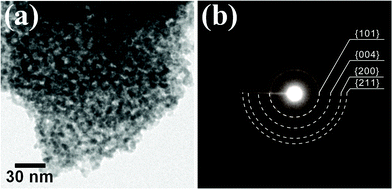 | ||
| Fig. 1 (a) A bright-field TEM micrograph and (b) corresponding electron pattern of the as-prepared mesoporous TiO2 powder. | ||
N2 adsorption-desorption isotherm plot of the as-prepared mesoporous TiO2 powder (Fig. 2) clearly showed a hysteresis loop induced by capillary condensation in the mesoporous channel in the relative pressure (P/P0) range of 0.4–0.8.22 The mean pore diameter was 5.4 nm and the pore size distribution calculated by Barret–Joyner–Halenda (BJH) model (inset). The Brunauer–Emmett–Teller (BET) specific area and the total pore volume of the as-prepared powder were 162 m2 g−1 and 0.218 cm3 g−1, respectively.
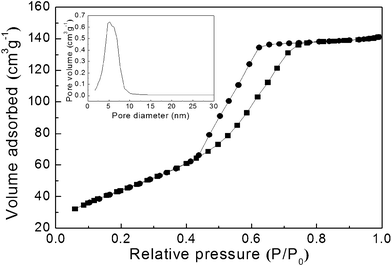 | ||
| Fig. 2 A N2 adsorption–desorption isotherm plot and BJH pore size distribution plot (inset) of the as-prepared mesoporous TiO2 powder. | ||
Prior to the sintering of the as-prepared mesoporous TiO2 powder, its thermal properties were characterized by thermogravimetic and differential scanning calorimeter (TG/DSC) analysis. As shown in Fig. 3, there are two regions of weight loss which is associated with one endothermic DSC peak and a few overlapped exothermic peaks. The first weight loss of ∼5.1% was attributed to the loss of physically adsorbed water, and it could be manifested by a clear endothermic DSC peak at around 100 °C. Between 230 and 570 °C (mostly at around 430 °C), a few overlapped exothermic peaks were observed in DSC accompanying with the second weight loss of ∼2.9% in the TG. In the literature, these overlapped exothermic peaks could originate from the removal of the residual organic surfactant.23,24 Therefore, the TG/DSC analysis indicates that the surfactant was not completely removed from the as-prepared mesoporous TiO2 powder, although it was calcined at 350 °C during the powder synthesis process.
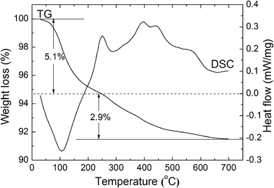 | ||
| Fig. 3 A thermogravimetic and differential scanning calorimeter (TG/DSC) analysis of the as-prepared mesoporous TiO2 powder. | ||
The as-prepared mesoporous TiO2 powder was consolidated by spark plasma sintering under the uniaxial pressure of 30 MPa for 5 min in the temperature range of 350– 600 °C. By the spark plasma sintering, we could obtain the bulky sintered bodies of the mesoporous TiO2 powder. The compressive strength of the sintered bodies monotonously increased with increasing temperature up to ∼25 MPa (Fig. 4). Therefore, it was manifested that the sintered body shown in the inset has a mechanical property of a bulky body, not a simple compact of the mesoporous TiO2 powder.
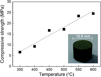 | ||
| Fig. 4 Compressive strength and a photograph (inset) of the bulky sintered body of the mesoporous TiO2 powder. | ||
Fig. 5 shows X-ray diffraction (XRD) patterns of the sintered bodies. Below 600 °C, only the atanase TiO2 phase was observed in the XRD pattern. When the sintering temperature reached 600 °C, a faint (110) peak of the rutile TiO2 phase started to be observed. Because the surface free energy in the anatase phase is lower than that in the rutile phase, the anatase phase is thermodynamically more stable than the rutile phase in TiO2 particles with a size smaller than a certain critical size.25 Banfield et al. proposed that the anatase phase can be transformed to the rutile phase only after growing to the critical size.26 The critical size is highly dependent on the temperature, pressure, and surface complexation condition.27–30 As shown in Fig. 5, we observed the very initial stage of the transformation from the anatase phase to the rutile phase. Therefore, the size of the primary TiO2 particle sintered at 600 °C (25 nm) is supposed to be very close to the critical size for the phase transformation in this experimental condition.
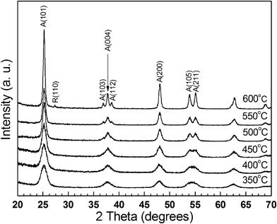 | ||
| Fig. 5 XRD patterns of the bulky mesoporous TiO2 structure consolidated by the spark plasma sintering. | ||
N2 adsorption–desorption isotherm plots of the sintered bodies of the mesoporous TiO2 powder are shown in Fig. 6(a). As well as the as-prepared mesoporous TiO2 powder in Fig. 2, all the samples showed a distinct large hysteresis loop above P/P0 = 0.4 even though they were consolidated by the spark plasma sintering at up to 600 °C. Because such behavior is a typical characteristic of type IV mesoporous materials due to the capillary condensation in the open mesoporous channels, it was confirmed that bulky mesoporous TiO2 structure was successfully fabricated by the direct sintering of the mesoporous powder in this experiment.22 The existence of the mesopores in the consolidated bodies can also be ascertained by BJH pore size distribution in Fig. 6(b). Porosity-related properties, such as specific surface area, total pore volume, porosity and average pore size, of the consolidated bodies were evaluated by BET and BJH models, and are listed in Table 1. The bulky samples sintered at 350 °C showed the largest specific surface area of ∼131 m2 g−1. In this case, the reduction of the specific surface area was less than 20% comparing to the as-prepared mesoporous TiO2 powder. The specific surface area and the total pore volume tend to decrease with the increase of the sintering temperature, while the average pore diameter increases. Because the origin of the porosity is the gap between the interconnected primary TiO2 particles, these properties are closely related with the size of the primary particle.21,31
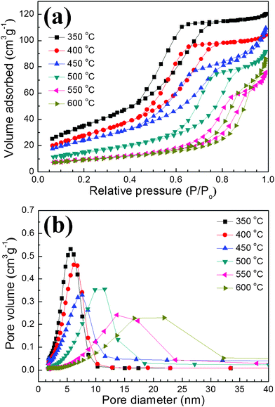 | ||
| Fig. 6 (a) N2 adsorption–desorption isotherm plots and (b) BJH pore size distribution of the bulky mesoporous TiO2 structures. | ||
| TEM crystallite size (nm) | Specific surface area (m2 g−1) | Total pore volume (cm3 g−1) | Porosity (%) | Average pore diameter (nm) | |
|---|---|---|---|---|---|
| As-prepared | 6.1 | 162 | 0.218 | 48 | 5.4 |
| SPS 350 °C | 6.0 | 131 | 0.186 | 44 | 5.7 |
| SPS 400 °C | 9.3 | 104 | 0.160 | 40 | 6.2 |
| SPS 450 °C | 13.0 | 89 | 0.169 | 42 | 7.6 |
| SPS 500 °C | 14.8 | 64 | 0.146 | 38 | 9.0 |
| SPS 550 °C | 20.0 | 33 | 0.102 | 30 | 12.4 |
| SPS 600 °C | 25.0 | 29 | 0.110 | 31 | 14.9 |
The primary particle sizes of the bulky mesoporous structures were characterized by using TEM (Fig. 7). The open interparticular porosity by the aggregation of the primary TiO2 nanoparticles, which originally existed in the as-prepared mesoporous TiO2 powder, was clearly observed in all samples after the sintering process. As the sintering temperature increases, an increase in the size of the primary TiO2 nanoparticle was observed in the TEM micrographs. Because the anatase phase has a truncated pyramidal shape rather than a sphere, the particle sizes were evaluated by the geometric average from 20 different particles.25 They were summarized in Table 1. The particle size in the 350 °C sintered sample (∼6.1 nm) was almost the same to that in the as-prepared powder (∼6.0 nm). Because the as-prepared powder was calcinated at 350 °C for 3 h before the sintering, the growth of the particle during the sintering at the same temperature in a very short process time (5 min) could be negligible.
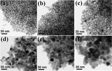 | ||
| Fig. 7 Bright-field TEM micrographs of the bulky mesoporous TiO2 structures consolidated at (a) 350 °C, (b) 400 °C, (c) 450 °C, (d) 500 °C, (e) 550 °C, and (f) 600 °C. | ||
At higher sintering temperatures, the size of the primary TiO2 particle was exponentially increased and the activation energy (ΔE) of the grain growth was ∼0.28 eV (Fig. 8). Interestingly, the activation energy of the increase of the pore diameter shows almost the same to that of the particle size growth above 450 °C. Because the increase of the particle size is accompanied by the expansion of the gap between the particles, the pore diameter shows the same tendency to the particle size. There was a linear relationship between the particle size and the pore diameter (particle size ∼ 1.66 × pore diameter). However, the tendency was not observed below 450 °C. As discussed in Fig. 3, most of DSC peaks were detected at around 430 °C. Therefore, the deviation of the activation energy below 450 °C could be regarded as the effect of the residual surfactant for the synthesis of the mesoporous TiO2 powder.
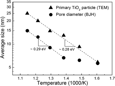 | ||
| Fig. 8 Arrhenius plot of the primary TiO2 particle size and the pore diameter. | ||
From the primary particle sizes in Table 1, we obtained the exponent, n, in eqn (1) with the following relation, and the best fit result was almost unity (n = 0.979).
 | (2) |
Conclusions
In summary, the bulky mesoporous TiO2 structure was fabricated by the direct consolidation of the mesoporous TiO2 powder. The mesoporous TiO2 powder, having disordered interconnections of primary TiO2 nanoparticles, was synthesized by a surfactant-mediated sol–gel method and its specific surface area and the total pore volume were 162 m2 g−1 and 0.218 cm3 g−1, respectively. The as-prepared powder was consolidated by the spark plasma sintering at 350 °C–600 °C. The bulky mesoporous TiO2 structure consolidated at 350 °C showed the largest specific surface area of 131 m2 g−1. Due to the open porosity in the mesoporous powder, bulky mesoporous TiO2 structures could be successfully sintered without significant grain growth. The primary particle size followed the linear grain growth (n = 1), and the porosity-related properties in the bulky mesoporous structure were strongly affected by the primary particle size.Acknowledgements
This research was supported by the Nano Material Technology Development Program through the National Research Foundation of Korea (NRF) funded by the Ministry of Education, Science and Technology (2011-0030147) and also supported by Korea Institute of Ceramic Engineering and Technology. The authors would like to acknowledge the assistance of So. Y. Lee with the TG/DSC and BET measurements.References
- A. Fujishima and K. Honda, Nature, 1972, 238, 37–38 CrossRef CAS.
- A. Wold, Chem. Mater., 1993, 5, 280–283 CrossRef CAS.
- A. Fujishima, X. Zhang and D. A. Tryk, Surf. Sci. Rep., 2008, 63, 515–582 CrossRef CAS.
- P. Yang, D. Zhao, D. I. Margolese, B. F. Chmelka and G. D. Stucky, Nature, 1998, 396, 152–155 CrossRef CAS.
- F. Huang, D. Chen, X. L. Zhang, R. A. Caruso and Y. Cheng, Adv. Funct. Mater., 2010, 20, 1301–1305 CrossRef CAS.
- D. V. Bavykin, V. N. Parmon, A. A. Lapkin and F. C. Walsh, J. Mater. Chem., 2004, 14, 3370–3377 RSC.
- A. Fernández, G. Lassaletta, V. M. Jiménez, A. Justo, A. R. González-Elipe, J.-M. Herrmann, H. Tahiri and Y. Ait-Ichou, Appl. Catal., B, 1995, 7, 49–63 CrossRef.
- J. A. Byrne, B. R. Eggins, N. M. D. Brown, B. McKinney and M. Rouse, Appl. Catal., B, 1998, 17, 25–36 CrossRef CAS.
- E. L. Crepaldi, G. J. de A.A. Soler-Illia, D. Grosso, F. Cagnol, F. Ribot and C. Sanchez, J. Am. Chem. Soc., 2003, 125, 9770–9786 CrossRef CAS.
- S. Y. Choi, M. Mamak, N. Coombs, N. Chopra and G. A. Ozin, Adv. Funct. Mater., 2004, 14, 335–344 CrossRef CAS.
- N. Krins, M. Faustini, B. Louis and D. Grosso, Chem. Mater., 2010, 22, 6218–6220 CrossRef CAS.
- A. Nakahira, T. Kubo and Y. Yamasaki, ACS Appl. Mater. Interfaces, 2010, 2, 136–1140 Search PubMed.
- A. Nakahira, M. Takimura and Y. Yamasaki, J. Non-Cryst. Solids, 2007, 353, 4203–4207 CrossRef CAS.
- A. Nakahira, H. Nagata, T. Onoki and Y. Yamasaki, Res. Chem. Intermed., 2008, 34, 347–352 CrossRef CAS.
- H. Nagata, N. Hirao, T. Onoki, Y. Baba, Y. Yamasaki and A. Nakahira, J. Ceram. Soc. Jpn., 2008, 116, 216–219 CrossRef CAS.
- Z. Z. Fang and H. Wang, Int. Mater. Rev., 2008, 53, 326–352 CrossRef CAS.
- H. Wang, Z. Z. Fang and K. S. Hwang, Metall. Mater. Trans. A, 2011, 42, 3534–3542 CrossRef CAS.
- D. Farkas, S. Mohanty and J. Monk, Phys. Rev. Lett., 2007, 98, 165502 CrossRef.
- C. E. Krill III, L. Helfen, D. Michels, H. Natter, A. Fitch, O. Masson and R. Birringer, Phys. Rev. Lett., 2001, 86, 842–845 CrossRef.
- M. J. Mayo and D. C. Hague, Nanostruct. Mater., 1993, 3, 43–52 CrossRef CAS.
- H. Luo, C. Wang and Y. Yan, Chem. Mater., 2003, 15, 3841–3846 CrossRef CAS.
- W. Y. Gan, M. W. Lee, R. Amal, H. Zhao and K. Chiang, J. Appl. Electrochem., 2008, 38, 703–712 CrossRef CAS.
- Y. Wang, S. Chen, X. Tang, O. Palchik, A. Zabzn, Y. Koltypin and A. Gedanken, J. Mater. Chem., 2001, 11, 521–526 RSC.
- H. Yun, K. Miyazawa, H. Zhou, I. Honma and M. Kuwabara, Adv. Mater., 2001, 13, 1377–1380 CrossRef CAS.
- A. S. Barnard and L. A. Curtiss, Nano Lett., 1997, 5, 1261–1266 CrossRef.
- H. Zhang and J. F. Banfield, J. Mater. Chem., 1998, 8, 2073–2076 RSC.
- W. Li, C. Ni, H. Lin, C. P. Huang and I. S. Shah, J. Appl. Phys., 2004, 96, 6663–6668 CrossRef CAS.
- A. A. Gribb and J. F. Banfield, Amer. Mineral., 1997, 82, 717–728 CAS.
- N. Masahashi, Mater. Sci. Eng., A, 2007, 452–453, 721–726 CrossRef.
- Y. I. Lee, J. H. Lee, S. H. Hong and D. Y. Kim, Mater. Res. Bull., 2003, 38, 925–930 CrossRef CAS.
- X. Hu, G. Li and J. C. Yu, Langmuir, 2010, 26, 3031–3039 CrossRef CAS.
- A. Rothschild, Y. Komen and F. Cosandey, Interface Sci., 2001, 9, 157–162 CrossRef CAS.
- M. Radecka, P. Sobas and M. Rekas, Solid State Ionics, 1999, 119, 55–60 CrossRef CAS.
| This journal is © The Royal Society of Chemistry 2012 |
