A facile electrochemical route for fast deposition of featherlike tellurium microstructures
Xuemei
Wang
and
Yonghong
Ni
*
College of Chemistry and Materials Science, Anhui Key Laboratory of Functional Molecular Solids, Anhui Normal University, Wuhu, 241000, P. R. China
First published on 27th January 2012
Abstract
In this paper, featherlike t-Te microstructures were synthesized at a large scale via a simple electrochemical deposition route at room temperature, employing Na2TeO3 as a tellurium source in a diluted HNO3 solution without the assistance of any additive. The phase and morphology of the as-prepared product were characterized by means of powder X-ray diffraction (XRD), energy dispersive spectrometry (EDS), (high resolution) transmission electron microscopy (HR/TEM), selected area electron pattern (SAED) and scanning electron microscopy (SEM). Some factors influencing the formation of featherlike t-Te microstructures were systematically investigated, including the deposition current, and the original amounts of Na2TeO3 and HNO3. The time-dependent shape evolution of featherlike t-Te microstructures was investigated. Experiments showed that diluted HNO3 was indispensable in the formation of featherlike t-Te microstructures.
1. Introduction
Recently, much attention has been paid to materials with branched structures since dendritic structures easily form continuous networks, usually have large surface areas, and allow for heterostructures compared with other structures. The materials with branched structures may provide new opportunities for wide applications of future nanodevices.1–3 It is a successful case that electrodeposited CuNi dendrites reported by Qiu and coworkers possessed good electrochemical property and could be prepared into a sensor for the detection of glucose.4 Many technologies have been developed for the preparation of various dendritic materials including metals, alloys, polymers and compounds.4–7 For example, Xie et al. designed a novel ultrasound-assisted template approach for preparation of Pd and Ag dendrites.5 Cho and co-workers obtained hierarchical polymer nanotrees via an electron-beam irradiation technique.1 Dendritic α-Fe2O3 micro-pines were hydrothermally synthesized by Cao et al. employing K3[Fe(CN)6] as original reactants at 140–200 °C for 2 days.3 Furthermore, Au,6Pb,8Bi9 and PbTe10dendrites were respectively prepared via electrochemical routes. However, few reports are found in the literature on the preparation of dendritic elemental semiconductors including tellurium (Te).As an important elemental semiconductor with a narrow band gap (0.35 eV), Te has been attracting much attention due to its good performances such as photoconductivity, thermoelectricity, high piezoelectricity, gas sensing and nonlinear optical properties, and potential applications in electronic and optoelectronic devices.11–15 Also, Te is used in some non-ferrous alloys and as a secondary vulcanizing agent in the natural rubber industry.16 Many methods have been developed for the preparation of Te micro/nanostructures, such as the hydrothermal synthesis,17 the refluxing polyol route,18 the microwave-assisted ionic liquid approach,19 the self-seeding or biomolecule-assisted solution process,20 the thermal-evaporation method,21 the ultrasound or visible light irradiation route,22 and the template-free electrodeposition.23 Some low-dimensional t-Te micro/nanostructures were obtained, including nanorods, nanowires, microtubes and nanobelts/nanoribbons. In 2004, Ujjal et al. reported a self-seeding solution route for the preparation of t-Te nanorods. They found featherlike t-Te microstructures could be obtained under high reactant concentrations.20a Meanwhile, employing the hydrothermal and solvothermal technology, they still prepared other t-Te nanostructures including nanowires, nanobelts and Y-junctions. Recently, Wang et al. designed a biphasic interfacial reaction route to successfully obtain t-Te with featherlike structures employing a mixed solvothermal technology.7 However, some shortcomings can be found in the aforementioned methods to fabricate featherlike Te, including use of organic reagents, slow growth rate, high reaction temperature, long reaction time and complex process. Also, the optimum conditions forming featherlike Te and the influencing factors were not systematically investigated. To conquer the above shortcomings, She and co-workers23 utilized the electrochemical deposition technique to realize the quick and cost-effective synthesis of 1D Te nanostructures. They potentiostatically deposited 1D Te nanostructures on the ITO substrate from a 1 M KOH solution at the deposition potential of −1.3 V at 85 °C for 30 min, employing TeO2 as the raw material without the assistance of any surfactant or template. Nevertheless, no featherlike microstructures or dendrites were obtained in their work.
In the present work, we design a simple electrochemical route for large synthesis of featherlike t-Te microstructures, employing Na2TeO3 as the Te source in a diluted HNO3 solution without the assistance of any additive. Different from She's work,23 featherlike t-Te microstructures were deposited in our experiment at room temperature by a galvanostatic method with a current of 8 mA for 5 min. Simultaneously, we systematically investigated the influences of some factors on the morphology of the final product, including the original amounts of Na2TeO3 and HNO3, deposition time and current. A possible formation process of featherlike t-Te microstructures was suggested.
2. Experimental section
All reagents were analytically pure, purchased from Shanghai Chemical Company and used without further purification.2.1 Electrodeposition of featherlike t-Te microstructures
In a typical experimental procedure, 0.5 mmol of Na2TeO3 was dissolved in 3 mL of diluted HNO3 solution (3.6 mM). Then, the twice-distilled water was added to form the electrolyte of 25 mL. To obtain the product, a simple three-electrode cell was used in our experiments, employing a Pt wire as the counter electrode, a saturated Ag/AgCl electrode as the reference electrode, and the indium tin oxide (ITO) glass with 1.0 × 1.0 cm2 as the working electrode. During the electrodeposition, the electrolyte was always immobile and the substrates were vertical in our experiments. The electrodeposition experiments were carried out in air by galvanostatic electrolysis with a current of 8 mA at room temperature for 5 min.2.2 Characterization
X-Ray diffraction (XRD) patterns of the typical structures of electrodeposition were recorded on a Shimadzu XRD-6000 X-ray diffractometer (Cu Kα radiation, λ = 0.154060 nm), employing a scanning rate of 0.02° s−1 and 2θ ranges from 10° to 80°. Scanning electron microscopy (SEM) images and energy dispersive spectra (EDS) of the final product were taken on a Hitachi S-4800 field emission scanning electron microscope, employing an accelerating voltage of 5 or 15 kV (15 kV for EDS). High resolution transmission electron microscopy (HR/TEM) images were recorded on a Tecnai G2 20 transmission electron microscope, employing an accelerating voltage of 200 kV.3. Results and discussion
3.1 Structure and morphology characterization
The morphology of the as-synthesized product was characterized by SEM and TEM. Fig. 1a shows a representative low-magnification SEM image of the final product. Plentiful featherlike products with ∼10 μm in length can be easily found. Further enlargement shows that featherlike structures are comprised of abundant regular and orderly nanosheets (see Fig. 1b). Fig. 1c depicts a typical TEM image of a nanosheet of broken off featherlike structures under ultrasonic action. Distinctly, the nanosheet still maintains the featherlike structure. The upper inset shown in Fig. 1c is a SAED pattern of the nanosheet. Regular diffraction dots show the single-crystal nature of the nanosheet. A typical HRTEM image of the product is shown in the lower inset in Fig. 1c, from which the clear stripes can be easily seen. This further confirms the good crystallinity of the product. The distance of the neighbouring planes is measured to be 0.604 nm, which corresponds to (001) plane of t-Te.24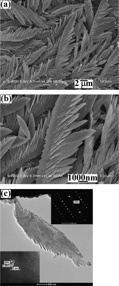 | ||
| Fig. 1 Electron microscopy images of featherlike products electrodeposited on ITO at the current of 8 mA for 5 min from the solution of 0.5 mmol Na2TeO3 + 3 mL diluted HNO3 + 27 mL distilled water: (a) a representative low magnification SEM image, (b) a high magnification SEM image, (c) a typical TEM image (the upper inset: a SAED pattern and the lower inset: a HRTEM image). | ||
The formation of Te is confirmed by the XRD pattern and EDS analysis of the as-obtained product. Fig. 2a shows the XRD pattern of the product obtained under the current experimental conditions. The locations of diffraction peaks are in good agreement with those of the standard Te form (see the bottom in Fig. 2a, JCPDS cards no.85-0554). Further evidence of the formation of Te came from the EDS analysis of the product, which was dispersed on a silicon substrate (see Fig. 2b). The strong Te peaks can be easily found and the weak Si peak can be ascribed to the Si support. C and O peaks should be attributed to the physical adsorption of carbon and oxygen in air in the product.
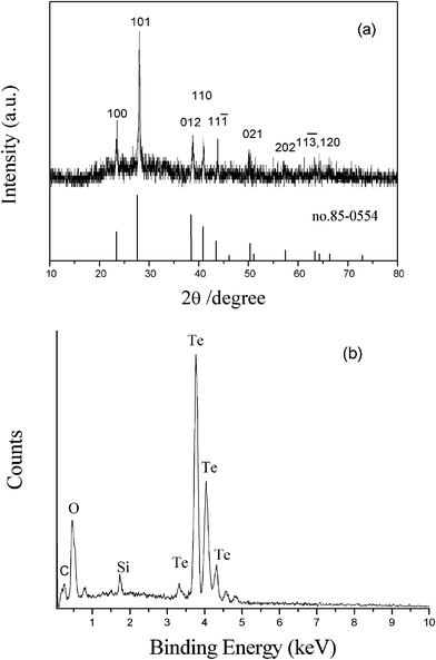 | ||
| Fig. 2 XRD pattern (a) and EDS analysis (b) of the product obtained from the system containing 0.5 mmol Na2TeO3 + 3 mL diluted HNO3 + 27 mL distilled water, at the deposition current of 8 mA in air for 5 min. | ||
3.2 The morphology evolution of featherlike t-Te microstructures
In order to explore the growth process of featherlike Te microstructures, we investigated the time-dependent shape evolution of the product. As shown in Fig. 3a, when the deposition time was 5 s, some spherical nanoparticles with diameters of 50∼150 nm were generated and most of the particles were connected with each other. Further enlargement showed these spherical particles were comprised of smaller nanoparticles (see the inset in Fig. 3a). After deposition for 30 s, more connected spherical-particles appeared. Simultaneously, the sizes of spherical particles increased to 150∼300 nm (see Fig. 3b). Upon further prolonging the deposition time to 90 s, SEM observations found that the connected spherical-particles disappeared and plentiful irregular particles were produced (Fig. 3c). These irregular particles should result from the oriented growth of the connected spherical-particles. When the time was prolonged to 3 min, some featherlike microstructures appeared besides irregular particles (Fig. 3d). After 5 min, a great deal of featherlike Te microstructures were obtained (see Fig. 1). After a longer time was employed, e.g. 10 min, featherlike microstructures disappeared and the product was composed of many sheets with micrometre sizes (see Fig. 3e). The above experiments clearly present the formation process of featherlike t-Te microstructures. In the initial stage, the deposited Te nucleated on the ITO substrate and grew into the connected spherical-nanoparticles. These spherical nanoparticles became the seeds for further growth of freshly produced Te atoms. Since the activities of different planes of seeds are different, anisotropic growth of Te appeared. This led to the production of irregular particles. Here, the rapid growth of some irregular particles resulted in the formation of some featherlike microstructures. With the prolonging of the time, more featherlike microstructures were prepared. When enough time was employed (e.g. 10 min), featherlike microstructures converted into micro-sheets in length due to the ceaseless growth. Moreover, with the prolonging of deposition duration, the TeO32− concentration in the system would reduce owing to the production of tellurium. The reduction peak current of TeO32−/Te pairs would decrease, which has been proven by our experiments. Fig. 4 shows the cyclic voltammetry curves of the glass–carbon electrode in the electrolyte with various deposition durations. Profiles of all curves are similar and the reduction peak currents gradually decrease from 5 s to 600 s. The above shape evolution process can be illustrated in Scheme 1.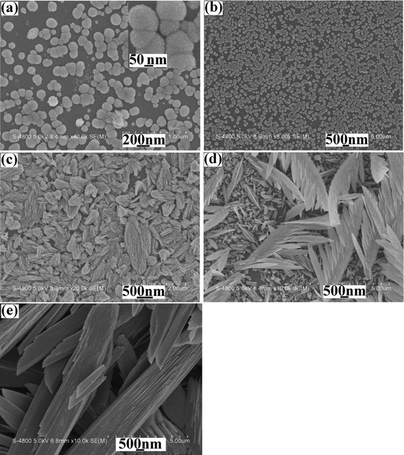 | ||
| Fig. 3 SEM images of the products electrodeposited in the same system with the current of 8 mA for different times: (a) 5 s, (b) 30 s, (c) 90 s, (d) 180 s and (e) 600 s. | ||
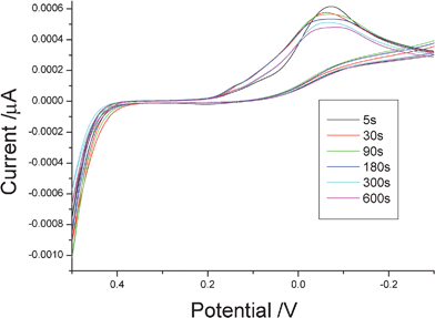 | ||
| Fig. 4 The cyclic voltammograms (CVs) of the glass–carbon electrode in the system containing 0.5 mmol Na2TeO3 + 3 mL diluted HNO3 + 27 mL distilled water with different deposition durations. | ||
 | ||
| Scheme 1 The time-dependent growth process of featherlike t-Te microstructures under the current electrodeposition conditions. | ||
Furthermore, we systematically investigated the influences of some experimental parameters on the morphology of the final product, such as the original amount of Na2TeO3 and HNO3, and the deposition current.
3.3 The influence of the original amount of Na2TeO3
While keeping the other conditions unchanged, we investigated the influence of the original Na2TeO3 amount on the morphology of the final product. As shown in Fig. 5a, when the original amount of Na2TeO3 was reduced to 0.25 mmol, the product was still composed of a great deal of featherlike microstructures. When 1.0 mmol Na2TeO3 was employed, featherlike microstructures disappeared and many cabbage-like products with various sizes were obtained (see Fig. 5b). The above facts clearly imply that the high original Na2TeO3 amount is unfavorable for the formation of featherlike t-Te microstructures.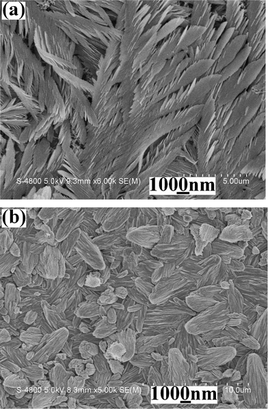 | ||
| Fig. 5 SEM images of the products obtained from systems containing different original amounts of Na2TeO3 under the same experimental conditions: (a) 0.25 mmol and (b) 1.0 mmol. | ||
3.4 The influence of the volume of HNO3
In 2006, Xiao et al.25 considered that Te sources existed in nitric acid solution in the form of HTeO2+ ions. The electrodeposition of Te behaved as a four-electron reduction from HTeO2+ to Te:| HTeO2+ + 3H+ + 4e− = Te + 2H2O E° = + 0.551 V25 | (1) |
Furthermore, the electrode reaction of TeO32−/Te pair is listed below:
| TeO32− + 3H2O + 4e− = Te + 6OH− E° = −0.57 V26 | (2) |
The above two reactions clearly indicate that the pH of the system can affect the formation of Te. According to eqn 2, it is difficult to deposit Te from a neutral or basic Na2TeO3 solution, which has been proven by the present work. When no nitric acid was used, the deposition reaction could not be evoked at the constant current of 8 mA. Here, the electrolyte was a clear Na2TeO3 solution with the pH 10.48. If nitric acid is introduced, the deposition reaction will occur according to eqn 1. Since the potential of HTeO2+/Te pair is affected by H+ concentration, the electrodeposition rate of Te changes with H+ ion concentrations. The bigger the H+ ion concentration is, the faster the deposition rate of Te. The above viewpoints were also confirmed by our experiments. For example, when 1.0 mL of 3.6 M HNO3 was introduced into the system droplet by droplet, a white precipitate firstly appeared in the electrolyte due to the generation of H2TeO3; then, the white H2TeO3 precipitate redissolved by excess HNO3. Here, the deposition reaction took place under the above same current. The product was composed of small flowerlike particles and big sheets (see Fig. 6a). After 3 mL of 3.6 M HNO3 was added, the pH of the system was measured to be 0.05. Under the same depositing conditions large featherlike products were obtained (see Fig. 1). Meanwhile, the pH of the system changed to 0.02. However, upon further increasing the volume of 3.6 M HNO3 to 5 mL and 7 mL, featherlike Te microstructures hardly changed besides the larger sizes (see Fig. 6b and 6c). Xiao et al. considered that the electrodeposition of Te was controlled by the diffusion of HTeO2+ ions to the electrode surface.25 In the present work, the diffusion rates of HTeO2+ ions to the electrode surface in the systems containing nitric acid from 3 mL to 7 mL were probably similar. As a result, the products deposited from the above systems had similar morphologies.
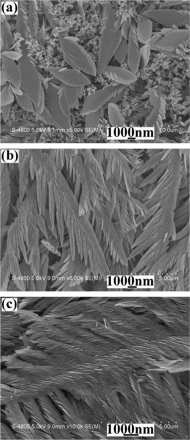 | ||
| Fig. 6 SEM images of the products prepared from the systems introduced various volumes of nitric acid at the deposition current of 8 mA for 5 min: (a) 1 mL, (b) 5 mL and (c) 7 mL. | ||
Also, the influence of the original Na2TeO3 amount on the morphology of the final product can be explained by the change of H+ ion concentrations. Under keeping the H+ ion concentration unchanged, the increase of the original Na2TeO3 amount accordingly reduced the H+ ion amount in the system due to the reaction between Na2TeO3 and H+ ions, which was unfavorable for the formation of featherlike microstructures.
3.5 The influence of deposition currents
Experiments showed that the morphology of the final product could be distinctly affected by the deposition current. Fig. 7 (a→c) exhibit the typical SEM images deposited from the same systems for 5 min at the deposition current of 4 mA, 6 mA and 10 mA, respectively. One can clearly see that the featherlike Te microstructures can only be obtained within the proper current range. Both the lower and the higher current are unfavorable for the formation of the featherlike microstructures. Usually, the deposition and growth rate of a product can be affected by the deposition current. Within the same deposition time, more tellurium atoms can be generated when increasing the deposition current. This increases the deposition, nucleation and growth rate of the final product. As a result, products with different morphologies can be obtained.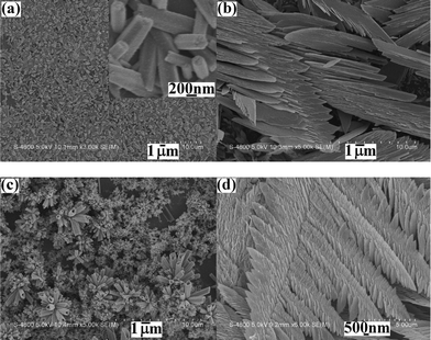 | ||
| Fig. 7 SEM images of the products deposited from the systems containing 0.5 mmol Na2TeO3 +3 mL diluted HNO3 + 27 mL distilled water, at different currents for 5 min: (a) 4 mA, (b) 6 mA and (c) 10 mA. (d) A typical SEM image of the product deposited on the Cu substrate under the above same system at the current of 8 mA for 5 min. | ||
Moreover, it was found that featherlike microstructures could be still deposited under the same experimental conditions when a Cu plate replaced ITO as the substrate (see Fig. 7d), indicating the deposition substrate has little influence on the formation of featherlike Te microstructures.
4. Conclusions
In summary, featherlike t-Te microstructures have been successfully obtained in a HNO3 solution by a simple electrochemical deposition route in air at room temperature, employing Na2TeO3 as the starting material. Time-dependent experiments showed that featherlike t-Te microstructures derived from the anisotropic growth of irregular particles. It was found that HNO3 played an important role in the formation of featherlike microstructures. Also, the high original Na2TeO3 amount was unfavorable for the formation of featherlike t-Te microstructures. Experiments showed that the featherlike microstructures could be obtained only in the proper ranges of deposition currents. Both the lower and the higher current were unavailable to the featherlike microstructures.Acknowledgements
The authors thank the National Natural Science Foundation of China (21171005) and Key Foundation of Chinese Ministry of Education (210098) for the fund support.References
- S. O. Cho, E. J. Lee, H. M. Lee, J. G. Kim and Y. J. Kim, Adv. Mater., 2006, 18, 60 CrossRef CAS.
- A. Sukhanova, A. V. Baranov, T. S. Perova, J. H. M. Cohen and I. NaPbev, Angew. Chem., Int. Ed., 2006, 45, 2048 CrossRef CAS.
- M. H. Cao, T. F. Liu, S. Gao, G. B. Sun, X. L. Wu, C. W. Hu and Z. L. Wang, Angew. Chem., Int. Ed., 2005, 44, 4197 CrossRef CAS.
- J. P. Xiao, Y. Xie, R. Tang, M. Chen and X. B. Tian, Adv. Mater., 2001, 13, 1887 CrossRef CAS.
- R. Qiu, X. L. Zhang, R. Qiao, Y. Li, Y. Kim and Y. S. Kang, Chem. Mater., 2007, 19, 4174 CrossRef CAS.
- W. C. Ye, J. F. Yan, Q. Ye and F. Zhou, J. Phys. Chem. C, 2010, 114, 15617 CAS.
- S. Wang, K. J. Zhang, H. Zhou, W. P. Guan, D. K. Ma, J. J. Lin, L. J. Zhang, S. M. Huang and J. C. Wang, CrystEngComm, 2010, 12, 3852 RSC.
- Y. H. Ni, Y. M. Zhang and J. M. Hong, CrystEngComm, 2011, 13, 934 RSC.
- Y. H. Ni, Y. M. Zhang, L. Zhang and J. M. Hong, CrystEngComm, 2011, 13, 794 RSC.
- (a) Y. H. Ni, Y. M. Zhang and J. M. Hong, CrystEngComm, 2011, 13, 1910 RSC; (b) Y. H. Ni, Y. M. Zhang and J. M. Hong, Cryst. Growth Des., 2011, 11, 2142 CrossRef CAS; (c) G. R. Li, C. Z. Yao, X. H. Lu, F. L. Zheng, Z. P. Feng, X. L. Yu, C. Y. Su and Y. X. Tong, Chem. Mater., 2008, 20, 3306 CrossRef CAS.
- P. Tangney and S. Fahy, Phys. Rev. B: Condens. Matter, 2002, 65, 054302 CrossRef.
- J. Beauvais, R. A. Lessard, P. Galarneau and E. J. Knystautas, Appl. Phys. Lett., 1990, 57, 1354 CrossRef CAS.
- A. W. Zhao, C. H. Ye, G. W. Meng, L. D. Zhang and P. M. Ajayan, J. Mater. Res., 2003, 18, 2318 CrossRef CAS.
- J. Lu, Y. Xie, F. Xu and L. Zhu, J. Mater. Chem., 2002, 12, 2755 RSC.
- T. Siciliano, E. Filippo, A. Genga, G. Micocci, M. Siciliano and A. Tepore, Sens. Actuators, B, 2009, 142, 185 CrossRef.
- Z. P. Liu, Z. K. Hu, Q. Xie, B. J. Yang, J. Wu and Y. T. Qian, J. Mater. Chem., 2003, 13, 159 RSC.
- H. T. Zhu, H. Zhang, J. K. Liang, G. H. Rao, J. B. Li, G. Y. Liu, Z. M. Du, H. M. Fan and J. Luo, J. Phys. Chem. C, 2011, 20, 316 Search PubMed.
- B. Mayers and Y. N. Xia, Adv. Mater., 2002, 14, 279 CrossRef CAS J. Mater. Chem. 2002, 12, 1875.
- Y. J. Zhu, W. W. Wang, R. J. Qi and X. L. Hu, Angew. Chem., Int. Ed., 2004, 43, 1410 CrossRef CAS.
- (a) K. Gautam Ujjal and C. N. R. Rao, J. Mater. Chem., 2004, 14, 2530 RSC; (b) Q. Y. Lu, F. Gao and S. Komarneni, Adv. Mater., 2004, 16, 1629 CrossRef CAS.
- H. Y. Chen, H. L. Lu, Y. G. Nie, J. H. Zhang, M. Z. Zhang, Q. Q. Dai, S. Y. Gao, S. H. Kan, D. M. Li and G. T. Zou, Phys. Lett. A, 2007, 362, 61 CrossRef CAS.
- B. Zhang, W. Y. Hou, X. C. Ye, S. Q. Fu and Y. Xie, Adv. Funct. Mater., 2007, 17, 486 CrossRef CAS.
- G. W. She, W. S. Shi, X. H. Zhang, T. L. Wong, Y. Cai and N. Wang, Cryst. Growth Des., 2009, 9, 663 CAS.
- Z. H. Wang, L. L. Wang and H. Wang, Cryst. Growth Des., 2008, 8, 4415 CAS.
- F. Xiao, B. Y. Yoo, M. A. Ryan, K. H. Lee and N. V. Myung, Electrochim. Acta, 2006, 52, 1101 CrossRef CAS.
- X. Z. Cao, T. Y. Song and X. Q. Wang, Inorganic Chemistry, 3rd section, 1994, High Education Publication Search PubMed.
| This journal is © The Royal Society of Chemistry 2012 |
