Porous nickel oxide nanospindles with huge specific capacitance and long-life cycle†
Huan
Pang
*a,
Bo
Zhang
ab,
Jimin
Du
a,
Jing
Chen
a,
Jiangshan
Zhang
a and
Sujuan
Li
a
aKey Laboratory for Clearer Energy and Functional Materials of HeNan Province, College of Chemistry and Chemical Engineering Department, Anyang Normal University, Anyang, 455000, HeNan, P.R. China. E-mail: huanpangchem@hotmail.com
bDepartment of Materials Science and Engineering, Nanjing University, Nanjing, 210093, P. R. China.
First published on 9th February 2012
Abstract
Porous nickel oxide nanospindles have been successfully synthesized by calcining a coordination complex precursor in air. The electrochemical test shows that the porous nickel oxide nanospindle electrode with an excellent specific capacitance reached a surprisingly high 1609 F g−1, and remained more than 83.3% after 3000 cycles at 10 A g−1. The excellent performance of the porous nickel oxide nanospindles suggests its promising application in supercapacitors.
In recent decades, due to depleting fossil fuel reserves, rising energy prices and escalating environmental problems, great efforts have been made to develop electrochemical systems for energy storage and conversion.1–4 With the increasing demand of high power portable electronic devices and electric vehicles, electrochemical capacitors that deliver higher power density than traditional batteries have been studied extensively in recent years.5–10
Transition metal oxides such as ruthenium oxide, manganese oxide, cobalt oxide, and nickel oxide are qualified to be electrochemical capacitor materials. Among these materials, nickel oxide (NiO) is of great significance, and the theoretical capacitance of nickel oxide can be ca. 2573 Fg−1 within 0.5 V. With the development of nanoscience, many groups found that nanomaterials generally exhibit many size and shape dependent properties, and the specific capacitance of NiO nanomaterials depended on the synthesis method and morphology.11–18 In particular, there have been considerable research efforts devoted to the use of nickel oxide for supercapacitors, due to its good pseudocapacitive behavior, practical availability, environmentally benign nature and low cost compared to the state-of-the-art supercapacitor material RuO2.13–15
Coordination complexes have been used as a nanostructured precursor to prepare mesoporous metal oxides in our previous work.19,20 The coordination complex precursor always has a micro or nanostructure due to the growth mechanism of the polymer complex precursor.19–23 More importantly, when calcining the nanostructured precursor, there were a large number of released gases from decomposed organic ligands and new pores were generated, finally resulting in a novel porous structure. This method needs neither template nor any surfactant. The coordination complex precursors have a uniform micro or nanostructured morphology due to the metal–organic coordination mechanism, and such unique nanostructure may bring on an exciting performance for utility in many fields.19,20
In this study, a nanospindle structured coordination complex precursor was successfully synthesized in aqueous solution under room temperature conditions. More importantly, by controlling the calcination condition, we can easily obtain porous NiO nanospindles. Unlike conventional approaches for preparing porous inorganic structures, this method avoids the subsequent complicated workup procedure for the removal of the hard template, seed or using soft template. Electrochemical tests have revealed that the prepared porous NiO nanospindle material has a large specific capacitance, good rate capability and extremely excellent cycling property. More importantly, we also further studied different electrochemical properties among NiO materials obtained under different calcination conditions. Other NiO nanostructures obtained by Wang et al.24 suggest porous NiO nanospindle electrodes have potential application in supercapacitors for their novel nanostructures.
In a typical synthesis, firstly, 0.200 g terephthalic acid, 0.054 g NaOH, 8.00 g H2O and 50.0 mL alcohol were mixed together and were stirred for 1 h continuously at room temperature. Secondly, 0.300 g Ni(NO3)2 were added into the above system. After stirring for 1 h continuously, a green precipitate can be obtained. The finally product was collected by centrifugation and washed with deionized water, ethanol several times then dried in air. Then the products were divided into three parts. P1 was calcined in the air at 465 °C for 30 min, P2 at 465 °C for 120 min, P3 at 465 °C for 6 h, respectively. The heating-up rate was 3 °C per min for all samples. The detailed synthesis method of ref. 24 (named M) can be seen in the ESI.†
In Scheme 1, we can see the whole synthetic process of the porous NiO nanospindles. A green precursor can be obtained by mixed Ni(NO3)2 and terephthalic acid alkaline alcohol solution. And then the coordination of terephthalic acid and Ni2+ can self-assemble into novel nanostructures in alkaline alcohol solution. A SEM image of the precursor is shown in Fig. S1a (ESI†), which shows that the size of the spindle-like precursor is about 1–1.5 μm. An XRD pattern of the precursor is shown in Fig. S1b (ESI†) which shows the good crystallinity of the precursors.
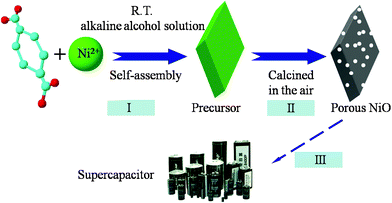 | ||
| Scheme 1 The synthetic process for porous NiO nanospindles. | ||
Fig. 1 shows the morphologies of the products after heat treatment at 465 °C for 30 min (P1). From Fig. 1a, the size of porous NiO nanospindles is about 1000 nm, some smaller than that of the precursor. The transmission electron microscopy (TEM) image shown in Fig. 1b demonstrates that the product P1 has porous nanospindles that are composed of nanoparticles, which leads to the polycrystalline SAED pattern (Fig. 1b left-inset). The crystalline nature of the porous NiO nanospindles were confirmed by a high-resolution HRTEM image (Fig. 1b right-inset), which displays clear lattices of the NiO crystal. The pictures in Fig. 1c–f show the TEM images of P1, P2, P3 and M respectively. From these images, we can easily conclude that the morphology of P2 is much like that of P1, but the nanospindle morphology is destroyed by a long calcination time. The morphology of P3 is quite different from that of P1. There are hardly any pores observed on P3 and the nanospindle morphology was destroyed completely. In Fig. 1f, some pores in M nanostructures may result from the decomposition of the other precursor (1,3,5-benzenrtricarboxylic acid nickel).
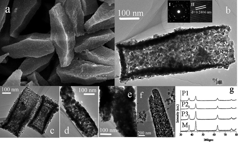 | ||
| Fig. 1 (a) SEM image of P1; (b,c) TEM images of P1 (inset of (b), I-SAED; II-HRTEM); (d) TEM image of P2; (e) TEM image of P3; (f) TEM image of M; (g) XRD patterns of four samples. | ||
Fig. 1g presents the XRD patterns of the four samples, which perfectly fit with the standard spectrum of NiO (JCPDS, No.47-1049). According to the XRD patterns, M has the sharpest peaks of all, which means that M has the best crystallinity. On the contrary, P1 has the worst crystallinity which may result from the large amount of pores and NiO nanocrystals shown clearly in Fig. 1b. When comparing the peaks of P1, P2 with P3 in Fig. 1g, we can draw a conclusion easily that the increase of the calcination time results in better crystallinity proven by different full width at half maximum of the peaks in the XRD patterns. Comparing the crystallinity of P1 with M, there is a big difference because of the different preparation methods and different nanostructures.
To gain further insight into the porous structure and pore size distribution of the NiO nanospindles, Brunauer–Emmett–Teller (BET) measurements were performed to examine its specific structural properties. The porous NiO nanospindles show a distinct hysteresis in the larger range ca. 0.5–1.0 P/P0 in Fig. 2a, indicating the presence of mesopores possibly formed by porous stacking of component nanoparticles.25,26 The BET surface area of P1 (102.7 m2 g−1) is much larger than that of P2 (36.1 m2 g−1), P3 (12.3 m2 g−1) and M (22.2 m2 g−1) making an efficient contact of the nanospindles with the electrolyte. The corresponding Barrett–Joyner–Halenda (BJH) pore size distribution curve (Fig. 2b) shows that the pore size is uniform, within the range of the mesopores (5–10 nm), while the pore size of P2 is not uniform and there is nearly no porous structure for P3. These porous nanospindle structures do not only offer high surface areas, but provide good electrolyte access. The morphology of nanospindles might offer a stable structure for ion intercalated/extracted into/out, which might improve the cycle life of the electrode.27–31
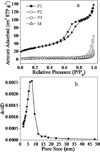 | ||
| Fig. 2 (a) The gas (N2) adsorption–desorption isotherm loops for P1, P2, P3 and M; (b) histogram of the pore size distribution data for the synthesized porous NiO nanospindles, P1. | ||
Cyclic voltammetry (CV) and chronopotentiometry (CP) measurements were used to evaluate the electrochemical properties and quantify the specific capacitance of as-prepared NiO electrodes. A nickel oxide capacitor in an alkaline solution relies on charge storage in the electric double layer at the electrode–electrolyte interface and charge storage in the host material through redox reactions on the surface and hydroxyl ion diffusion in the host material.32,33Fig. 3a shows the CV curves of P1 at different scan rates. The potential span is from 0 to 0.55 V (vs.SCE) in 3 wt.% KOH aqueous solution. It is clear that the redox peaks reveal the Faradaic pseudocapacitive property of the porous NiO nanospindles based on the surface redox mechanism of Ni2+ to Ni3+ at the surface of porous NiO nanospindles according to the following equation, NiO + OH− → NiOOH + e−. The large current densities suggest remarkably large specific capacitances of P1. Specific capacitance is essential to the application of supercapacitors and in most cases the most important factor considered. It is the huge specific capacitances of supercapacitors that distinguish them from common batteries and capacitors. The specific capacitances of P1, P2, P3 and M are calculated according to the CV curves at different scan rates and the clear relationships are shown in Fig. 3b.
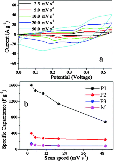 | ||
| Fig. 3 (a) Cyclic voltammetry curves of P1 at different scan rates; (b) the specific capacitances of P1, P2, P3 and M calculated according to the CV curves at different scan rates. | ||
The specific capacitance of P1 can reach a surprising 1609 F g−1 at the scan rate of 2.5 mV s−1 (ESI† Calculation1), much larger than the reports of NiO electrodes in ref. 19,34. Even though the specific capacitance of P1 drops as the scan rate increases, the specific capacitance is still very large, about 685 F g−1 at the scan rate of 50 mV s−1. The drop can be explained by the ion-exchange mechanism.32,33 The OH− needs enough time to transfer between the solution into the surface of porous NiO nanospindles in order to be intercalated/extracted into/out of the NiO when charging/discharging. If the scan rate is low, such as 2.5 mV s−1, the OH− can have enough time to transfer and much more charge transfers than at a high scan rate, which means more charge can be stored and thus higher specific capacitance. In contrast to P1, the specific capacitances of the other three electrodes are much smaller than that of P1 at any scan rate. Based on the TEM images in Fig. 1 and the BET results in Fig. 2, fewer pores or different nanostructures of P2, P3 and M might be important reasons. With many connecting pores, materials such as P1 have more channels to let the ions go through, which can enhance the travelling speed of the ions and thus bring the high specific capacitances. On the contrary, the good crystallinity of M can make the transfer of the ions in and out of the materials difficult.
CP curves at different current densities are shown in Fig. 4a. The symmetrical characteristic of charging/discharging curves is good, which means that the porous NiO nanospindle electrodes with excellent electrochemical capability and redox process are reversible. The relationships between the specific capacitances calculated by the CP curves and current densities are given in Fig. 4b (for detailed calculation see ESI† calculation 2 and 3). Based on the CV curves, P1 also has the largest specific capacitance of all the four. The specific capacitance reaches 1462 F g−1 at a current density of 1.0 A g−1 and remains at 1200 F g−1 even at 10.0 A g−1. The huge specific capacitance at large current densities indicates the application of this kind of NiO in many fields such as peak power sources. On the contrary, the other samples, P2, P3 and M, have much smaller specific capacitances in accordance with the data from the CV curves. This makes it clear that the calcination time and nanostructure are very important factors for controlling the electrochemical properties of NiO nanostructured electrode materials.
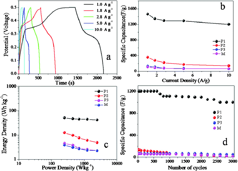 | ||
| Fig. 4 (a) CP curves of P1 at different current densities; (b) the specific capacitances calculated by the CP curves and current densities of P1, P2, P3, M; (c) the relationship of the specific energy against specific power for different NiO electrodes materials; (d) the relationships of the specific capacitance against cycling number for different NiO materials with current density 10.0 A g−1 | ||
Besides the large specific capacitance, another advantage of supercapacitors is that they have both large power density and large energy density at the same time. This unique property ensures the wide use of supercapacitors in many fields which need both large power density and large energy density. Fig. 4c shows the relationship of the specific energy against specific power for different NiO electrode materials. From Fig. 4c, it is easily concluded that P1 has the best performance for both the power density and the energy density. When its power density is 250 W kg−1, its energy density is about 50.7 W h kg−1. Meanwhile, these values of P2, P3, W are 12.5, 4.5, 3.8 W h kg−1, respectively. What's more, when the power density is 2500 W kg−1, its energy density surprisingly remains 41.7 W h kg−1, while those of other electrodes are less than 5.0 W h kg−1. Its terrific power density and energy density as well as the large specific capacitance make it a promising candidate for the electrode materials of supercapacitors.
It is also very important for electrode materials to have good specific capacitance retention. The supercapacitors should work steadily and safely, which requires the specific capacitance of electrode materials to change as little as possible. The relationships of the specific capacitance against cycling number of the four kinds of materials are shown in Fig. 4d. The relationship of P1 shows its excellent specific capacitance retention under large current density 10.0 A g−1. After 600 continuous charge–discharge cycles, P1 almost remains the same specific capacitance as its initial value, while others drop a lot. P1 still retains more than 90.8% of its specific capacitance after 2000 continuous charge–discharge cycles. Even after 3000 continuous charge–discharge cycles, P1 t more than 83.3% and the specific capacitance is about 1000 F g−1, which is still quite a large value. The little drop of specific capacitance of P1 possibly results from the slight collapse of the novel nanospindle structures when the ions are intercalated/extracted into the novel nanospindle structures compared to the other three structures (ESI,† Fig. S2).
From ESI Fig. S2a, there are very few changes of the novel porous nanospindle structures after 3000 charge–discharge cycles, while the other structures changed into formless particles (ESI,† Fig. S2b–d). Even though there is some specific capacitance decrease, the specific capacitance is still very large after long cycles for the P1 electrode, which make them practical for applications in the future.
The electrode kinetics of the as-prepared material electrodes were estimated by electrochemical impedance spectra (EIS). Fig. S3 (ESI†) shows the EIS of the electrodes of P1, P2, P3, M at room temperature. The EIS data can be fitted by an equivalent circuit consisting of a bulk solution resistance Rs, a charge-transfer Rct, a pseudocapacitive element Cp from the redox process of NiO, and a constant phase element (CPE) to account for the double-layer capacitance, as shown in inset of Fig. S3 (ESI†). The solution resistance Rs of these four composites was measured to be 3.2, 2.9, 4.6 and 4.4 Ω, respectively, while the charge-transfer resistance Rct was calculated (by ZSimpWin software) to be 4.6, 12.2, 14.5 and 17.9 Ω, respectively. This clearly demonstrates the reduced charge-transfer resistance of the porous NiO nanospindles electrode. In addition, the charge-transfer resistance Rct, also called Faraday resistance, is a limiting factor for the specific power of the supercapacitor.35,36 It is the low Faraday resistance that results in the high specific power of the porous NiO nanospindle electrode. The charge-transfer resistance Rct of the P1 electrode is the lowest of all, which makes high electric activity. More importantly, the porous structure of P1 allows ions or electrolyte transfer to occur quickly.
In summary, porous NiO nanospindles have been prepared by a simple and cost-effective approach. A huge specific capacitance of the electrode has been reported based the porous NiO nanospindle structures. The effects of calcination time on the electrochemical supercapacitive properties have been studied by the corresponding electrochemical tests. We also have compared electrochemical properties with samples from Wang's report. The results suggest that the porous NiO nanospindle electrode can reach excellent specific capacitance, 1609 F g−1 and retains more than 83.3% specific capacitance after 3000 continuous charge–discharge cycles. The stable porous nanospindles might offer important information that physical and chemical properties of nanostructured materials are related with their nanostructures, and the precise control of the morphology of nanomaterials would serve to maximize the performance. The excellent capacitive properties make the porous NiO nanospindles one of the most promising candidates for the application of electrode materials of supercapacitors.
This work is supported by the National Natural Science Foundation of China (21003001, 21071006 & 21105002) HeNan Province of International Science & Technology Coopperation (11430051003) and the projects of Ministry of Education of returned overseas students.
References
- C. Liu, F. Li, L. P. Ma and H. M. Cheng, Adv. Mater., 2010, 22, E28–E62 CrossRef CAS.
- P. Simon and Y. Gogotsi, Nat. Mater., 2008, 7, 845–854 CrossRef CAS.
- S. Chen, J. W. Zhu, X. D. Wu, Q. F. Han and X. Wang, ACS Nano, 2010, 4, 2822–2830 CrossRef CAS.
- V. Subramanian, H. W. Zhu, R. Vajtai, P. M. Ajayan and B. Q. Wei, J. Phys. Chem. B, 2005, 109, 20207–20214 CrossRef CAS.
- P. J. Hall, M. Mirzaeian, S. I. Fletcher, F. B. Sillars, A. J. R. Rennie, G. O. Shitta-Bey, G. Wilson, A. Cruden and R. Carter, Energy Environ. Sci., 2010, 3, 1238–1251 CAS.
- Y. B. He, G. R. Li, Z. L. Wang, C. Y. Su and Y. X. Tong, Energy Environ. Sci., 2011, 4, 1288–1292 CAS.
- K. Chang and C. Hu, J. Electrochem. Soc., 2004, 151, A958 CrossRef CAS.
- P. Soudan, J. Gaudet, D. Guay, D. Belanger and R. Schulz, Chem. Mater., 2002, 14, 1210 CrossRef CAS.
- J. P. Zheng, P. Cygon and T. R. Jow, J. Electrochem. Soc., 1995, 142, 2699 CrossRef CAS.
- D. D. Zhao, S. J. Bao, W. J. Zhou and H. L. Li, Electrochem. Commun., 2007, 9, 869–874 CrossRef CAS.
- C. Z. Yuan, B. Gao and X. G. Zhang, J. Power Sources, 2007, 173, 606–612 CrossRef CAS.
- C. Z. Yuan, B. Gao, L. H. Su and X. G. Zhang, Solid State Ionics, 2008, 178, 1859–1866 CrossRef CAS.
- K. H. Chang, C. C. Hu and C. Y. Chou, Chem. Mater., 2007, 19, 2112–2119 CrossRef CAS.
- C. Z. Yuan, L. Chen, B. Gao, L. H. Su and X. G. Zhang, J. Mater. Chem., 2009, 19, 246–252 RSC.
- W. Xing, F. Li, Z. F. Yan and G. Q. Lu, J. Power Sources, 2004, 134, 324–330 CrossRef CAS.
- F. Jiao, A. H. Hill, A. Harrison, A. Berko, A. V. Chadwick and P. G. Bruce, J. Am. Chem. Soc., 2008, 130, 5262–5263 CrossRef CAS.
- H. W. Yan, C. F. Blanford, B. T. Holland, M. Parent, W. H. Smyrl and A. Stein, Adv. Mater., 1999, 11, 1003–1006 CrossRef CAS.
- Y. G. Wang and Y. Y. Xia, Electrochim. Acta, 2006, 51, 3223–3227 CrossRef CAS.
- H. Pang, Q. Y. Lu, Y. C. Li and F. Gao, Chem. Commun., 2009, 7542–7544 RSC.
- F. Gao, H. Pang, S. P. Xu and Q. Y. Lu, Chem. Commun., 2009, 3571–3573 RSC.
- O. M. Yaghi, C. E. Davis, G. M. Li and H. L. Li, J. Am. Chem. Soc., 1998, 119, 2861–2868 CrossRef.
- C. J. Kepert, T. J. Prior and M. J. Rosseinsky, J. Am. Chem. Soc., 2000, 122, 5158–5168 CrossRef CAS.
- Z. Q. Wang, V. C. Kravtsov and M. J. Zaworotko, Angew. Chem., Int. Ed., 2005, 44, 2877–2880 CrossRef CAS.
- D. C. Wang, W. B. Ni, H. Pang, Q. Y. Lu, Z. J. Huang and J. W Zhao, Electrochim. Acta, 2010, 55, 6830–6835 CrossRef CAS.
- J. Y. Baek, H. W. Ha, I. Y. Kim and S. J. Hwang, J. Phys. Chem. C, 2009, 113, 17392–17398 CAS.
- X. F. Zhou, Z. L. Hu, Y. Q. Fan, S. Chen, W. P. Ding and N. P. Xu, J. Phys. Chem. C, 2008, 112, 11722–11728 CAS.
- S. L. Xiong, C. Z. Yuan, X. G. Zhang, B. J. Xi and Y. T. Qian, Chem.–Eur. J., 2009, 15, 5320 CrossRef CAS.
- J. C. Park, J. Kim, H. Kwon and H. Song, Adv. Mater., 2009, 21, 803–807 CrossRef CAS.
- C. C. Hu, K. H. Chang, M. C. Lin and Y. T. Wu, Nano Lett., 2006, 6, 2690–2695 CrossRef CAS.
- X. Xia, J. Tu, X. Wang, C. Gu and X. Zhao, J. Mater. Chem., 2011, 21, 671–679 RSC.
- Y. Gao, S. Chen, D. Cao, G. Wang and J. Yin, J. Power Sources, 2010, 195, 1757–1760 CrossRef CAS.
- C. Z. Yuan, X. G. Zhang, L. H. Su, B. Gao and L. F. Shen, J. Mater. Chem., 2009, 19, 5772–5777 RSC.
- R. Barnard, C. F. Randell and F. L. Tye, J. Appl. Electrochem., 1980, 10, 109–116 CrossRef CAS.
- H. Pang, Q. Y. Lu, Y. Z. Zhang, Y. C. Li and F. Gao, Nanoscale, 2010, 2, 920–922 RSC.
- B. E. Conway, Electrochemical supercapacitors: Scientific fundamentals and technological applications, Kluwer Academic/Plenum Publishers, New York, 1997 Search PubMed.
- J. F. Zang, S. J. Bao, C. M. Li, H. J. Bian, X. Q. Cui, Q. L. Bao, C. Q. Sun, J. Guo and K. R. Lian, J. Phys. Chem. C, 2008, 112, 14843–14847 CAS.
Footnote |
| † Electronic Supplementary Information (ESI) available: Experimental detail, electrode preparation, characterization and calculation. See DOI: 10.1039/c2ra00949h/ |
| This journal is © The Royal Society of Chemistry 2012 |
