One-pot synthesis of mesoporous interconnected carbon-encapsulated Fe3O4 nanospheres as superior anodes for Li-ion batteries†
Jun
Liu
a,
Yichun
Zhou
*a,
Fei
Liu
bc,
Chunping
Liu
a,
Jinbin
Wang
a,
Yong
Pan
a and
Dongfeng
Xue
*bc
aKey Laboratory of Low Dimensional Materials & Application Technology, Ministry of Education, Faculty of Materials, Optoelectronics and Physics, Xiangtan University, 411105, China. E-mail: zhouyc@xtu.edu.cn; Fax: (+) 86-731-58293586; Tel: (+)86-731-58298119
bSchool of Chemical Engineering, Dalian University of Technology, 116023, China
cState Key Laboratory of Rare Earth Resource Utilization, Changchun Institute of Applied Chemistry, Chinese Academy of Sciences, Changchun 130022, China. E-mail: dongfeng@ciac.jl.cn
First published on 9th February 2012
Abstract
Mesoporous interconnected carbon-encapsulated Fe3O4 (Fe3O4@C) nanospheres assembled from tiny nanoparticle subunits have been synthesized by a one-pot solvothermal decomposition route followed by thermal annealing. Electrochemical characterization of these interconnected Fe3O4@C nanospheres exhibits a capacity of 636 mA h g−1 at 0.2–1 C over 50 cycles when employed as anode materials in Li-ion batteries.
Growing demand for high energy and power density Li-ion batteries has shifted the attention from graphitic anodes, with a theoretical capacity of 372 mA h g−1, to many oxides, alloys and hybrid materials with higher specific capacity.1,2 Transition metal oxides, with a reversible capacity between 600–1000 mA h g−1, have emerged as alternative materials that can potentially replace graphite based anodes.3–7 Amongst them Fe3O4 attracts attention for its high specific capacity and high electrical conductivity, natural abundance, and environmental friendliness.8–12 However, due to the large volume dilation involved in the Li+ uptake and release, the transition metal oxide based anodes disintegrate resulting in capacity fade and poor cycling performance. Constructing nanostructured electrode materials can enhance the electrochemical performances that could not be achieved in bulk materials, benefiting from the large surface area and short diffusion path in nanostructured electrode materials.13–15 In particular self-assembled hierarchical-like nanostructured electrode materials attract much attention in a variety of fields because of their extraordinarily high active surface/interface and robust stability.13 For example, Reddy and co-workers fabricated one-dimensional electrospun materials of TiO2 nanofibers and rice grain shaped TiO2 by the electrospinning method, which show long-term cycling stability and stable performance up 800 cycles.15 Coating metal oxide nanostructures with a conductive and elastic carbon layer is another effective strategy to improve structural integrity and hence the cycling stability of electrodes, where the carbon overcoating can effectively buffer the strain caused by structured and volume changes and prevent the aggregation of active metal oxides during cycling.8,16,17 For example, using a self-assembled three-dimensional graphene material with high conductivity and large specific surface area as the conductive additive and supporting matrix, Liet al. fabricated a hierarchically nanostructured composite comprising MnO2, graphene and poly(3,4-ethylenedioxythiophene) for greatly improved performance of Li-ion batteries. In this regard, various solution-based approaches, such as sol–gel, thermal decomposition, and hydrothermal methods have been pursued in the literature for the coating of Fe3O4 nanostructures with conductive carbon-based materials.9–12 Generally, the above routes for such coated nanocomposites are usually multi-step (including firstly fabricating of Fe3O4, followed surface modification, and finally coating), time-consuming and tedious, which significantly hinders the process scale-up.9–11 In this communication, we present a simple one-pot solvothermal decomposition route to synthesize mesoporous interconnected Fe3O4@C nanospheres assembled from tiny nanoparticle subunits without using any templates and surfactants. When evaluated as an anode material for Li-ion batteries, the annealed Fe3O4@C nanospheres exhibit exceptional cycling performance at a 0.2 C rate with a capacity of 834 mA h g−1 after 30 cycles.
Solvothermal crystallization is an effective and versatile route for tuning the microstructure of metal oxide electrode materials. Through precisely selecting appropriate reactants and solvents in solvothermal synthetic routes, we can even control the microstructure of oxide-based nanocomposites.18–22 Recently, we have successfully constructed hierarchical V2O5–SnO2 double-shelled nanocapsules and multiple NaNbO3–Nb2O5 heterostructure nanotubesvia a one-pot solvothermal crystallization route.21,22 This implies that selecting appropriate metal complexes as precursors, metal-conductive carbon nanocomposites with fine morphology can be achieved via a one-pot solvothermal decomposition route. In this work, by utilizing ferrocene as a single reactant (both as iron and carbon sources), we reported the synthesis of mesoporous interconnected Fe3O4@C nanospheres assembled from tiny nanoparticle subunits via a one-step solvothermal decomposition route. Scheme 1 gives the detailed illustration of the fabrication of uniform Fe3O4@C nanospheres. In the process of ferrocene decomposition, iron atoms firstly were oxidized into magnetite under the assistance of hydrogen peroxide (Scheme 1a). With an increase of concentration of magnetite, the magnetite nanocrystals under supersaturated solution aggregated into larger secondary clusters to lower the system energy (Scheme 1b).20,21 Then the nanohybrid materials with conjugated double bonds can be adsorbed on the surface of magnetite nanoparticles by chemical bonding, leading to the formation of core-shell nanostructure (Scheme 1c).7 After simple annealing under an N2 atmosphere, a thin carbon layer was simultaneously generated on the surface of the nanospheres from carbonization of absorbed organic macromolecular residues, resulting in the formation of mesoporous Fe3O4@C nanospheres. This synthesis method is simple and easily scaled up (see ESI† for details).
 | ||
| Scheme 1 Schematic of formation process of mesoporous Fe3O4@C nanospheres: (a) tiny Fe3O4 nanoparticles were formed viaferrocene decomposition in the presence of hydrogen peroxide; (b) larger secondary clusters were achieved via aggregating of these tiny nanoparticles under supersaturated solution to lower the system energy; (c) a thin carbon layer was generated on the surface of Fe3O4 nanosphere clusters during the annealing process, resulting in mesoporous interconnected Fe3O4@C nanospheres assembled from tiny nanoparticle subunits. | ||
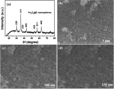
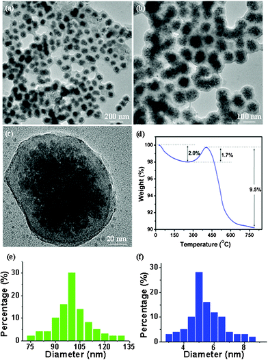
X-Ray diffractometry (XRD) analysis indicates the presence of only the cubic magnetite phase (JCPDS file no. 19–0629) in the as-synthesized interconnected nanospheres as shown in Fig. 1a. The small crystallite size of the Fe3O4 nanospheres is evidenced by the broadening intensity of the diffraction peaks. Fig. 1b–d shows typical scanning electron microscopy (SEM) images of these nanocomposites. A low-magnification image (Fig. 1b) of the products shows that these samples are spherical with an average diameter of about 100 nm and a relatively narrow size distribution. Fig. 1b and c with high magnification show these spherical nanospheres were interconnected, resulting porous self-assembled nanoparticles with rough surface. Such microstructured nanocomposites held great promise in offering sufficient surface area to facilitate electrochemical reactions with respect to the bulk counterpart. All these morphology and structure details of the interconnected Fe3O4@C nanospheres are further characterized by transmission electron microscopy (TEM), as shown in Fig. 2a–c. Low-magnification TEM images (Fig. 2a and b) show that all these Fe3O4 nanospheres were coated with a uniform thin carbon layer, having an obvious core–shell nanostructure. A high-magnification TEM image (Fig. 2c) reveals that the magnetite core is a secondary nanostructure composed of dozens of primary Fe3O4 nanoparticles with a size of about 5 nm and an amorphous carbon shell with a thickness of about 10 nm is distributed on the surface of magnetite cores. The size distribution curves of these Fe3O4@C nanospheres and tiny Fe3O4 nanoparticles are shown in Fig. 2e and 2f, respectively, which were obtained from TEM analysis. From these size distribution curves, it can be seen that these Fe3O4@C nanospheres have an average diameter of ∼100 nm, and the primary Fe3O4 nanoparticles have an average size of ∼5 nm. In order to quantify the weight percentage of carbon in these nanosphere composites, thermogravimetric analysis (TGA) was carried out. The TGA plot (Fig. 2d) shows a weight loss of 2% up to 250 °C is attributed the release of water absorbed on the sample, and a weight gain of 1.7% in the range 250–400 °C is believed to correspond to the oxidation of Fe3O4 in air. In a typical thermogravimetric process in air for Fe3O4, the Fe3O4 can be oxidized to Fe2O3 with a weigh gain of 3.45%, based on the complete oxidation of Fe3O4. At about 420 °C, the carbon content in the samples starts to be oxidized to CO2 gas making the mass of the sample decreases slowly. The total weight loss in the TGA curves is 9.8%, in which the weight loss of adsorbed water is 2%, and thus the carbon content is calculated to be 11.25% (7.8% + 3.45%).
 | ||
| Fig. 1 (a) XRD pattern of mesoporous interconnected Fe3O4@C nanospheres, all the diffraction peaks can be well matched with those of magnetite (JCPDS no. 19-0629); (b–d) different magnification SEM images of interconnected Fe3O4@C nanospheres, which have a uniform size of about 100 nm. | ||
 | ||
| Fig. 2 (a,b) Low-magnification TEM images of mesoporous interconnected Fe3O4@C nanospheres which clearly show that Fe3O4 nanoclusters were fully encapsulated with carbon layers; (c) high-magnification TEM image of a separated Fe3O4@C nanospheres showing that the average size of tiny Fe3O4 nanoparticle subunits is ∼5 nm; (d) TGA curve of Fe3O4@C nanospheres; (e) the size distribution curves of Fe3O4@C nanospheres; (f) the size distribution curves of the tiny Fe3O4 nanoparticles. | ||
For the electrochemical performance of final nanohybrid anode materials, the carbon content of mesoporous Fe3O4@C nanospheres is a pivotal factor, as only an adequately solid carbon layer is sufficient for the large stress occurring due to volume change.9,17 However, it should be noted that superfluous carbon content is unfavorable to reach an optimal capacity despite its good capacity retention because the capacity of amorphous carbon is much smaller than that of Fe3O4 (372 mA h g−1vs. 924 mA h g−1).10 Previous research has shown that the uniformity and optimum content of the coated carbon is a precondition for ensuring that the electrode structure integrity is maintained during lithiation/delithiation process and thus end up with a satisfactory cycling life.9,17 All these results indicate that the introduction of an appropriate carbon component to form a uniform Fe3O4@C core–shell nanostructure increases the utilization efficiency of the Fe3O4 and improves the cycle life of Li-ion battery electrodes by reducing the pulverization problem and increase the electronic conductivity (Table S1, see ESI† for details). In the current solvothermal decomposition system, the carbon content of Fe3O4@C nanospheres can be facilely controlled via adjusting the duration time of the solvothermal treatment (the carbon content increases as the solvothermal time prolongs), which is consistent with previous report on carbon-coated oxide nanospheres.17 Thereby, we chose an optimum solvothermal time (24 h) for the optimum content of the coated carbon (∼11.25%), which can effectively maintain the integrity of electrode structure and enhance the electronic conductivity of Fe3O4.
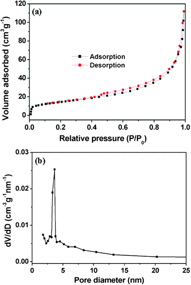
The surface area of these porous interconnected Fe3O4@C nanospheres were measured using the Brunauer–Emmett–Teller (BET) method. Fig. 3a shows the N2 adsorption–desorption isotherm at 77 K and the pore size distribution by the Barrett–Joyner–Halenda (BJH) method. The isotherm can be classified as a typical III isotherm with a hysteresis loop, which suggests the presence of a mesoporous structure and BET specific surface area of 51.72 m2 g−1. The shape of the pore size distribution curve indicates that these Fe3O4@C nanospheres are mesoporous materials and display a narrow pore size distribution in the range 3–4 nm (Fig. 3b).
 | ||
| Fig. 3 N2 adsorption–desorption isotherm (a) and the corresponding pore size distribution (b) of mesoporous interconnected Fe3O4@C nanospheres calculated using BJH method. | ||
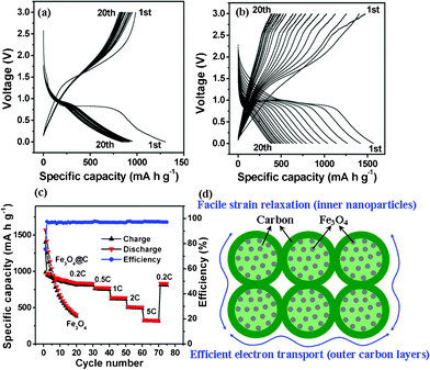
Fig. 4a shows voltage–capacity curves of these mesoporous interconnected Fe3O4@C nanospheres at 0.2C rate (5 h per half cycle, 180 mA g−1). It is striking to note that a high reversible capacity of about 837 mA h g−1 was achieved after 20 cycles (Fig. 4a). For comparison, we fabricated a bare Fe3O4 nanoparticle (Fig. S1, see ESI† for details) anode and the bare Fe3O4 showed only 43% retention of the initial reversible capacity after 20 cycles (400 mA h g−1, Fig. 4b). The high reversible capacity of these mesoporous interconnected Fe3O4@C nanospheres can probably be attributed the distinct electrochemical activity of porous and hierarchical Fe3O4 nanospheres and a synergetic effect of Fe3O4 and thin carbon layer.9,11 After 30 cycles, the same cell was further evaluated for rate capability as shown in Fig. 4c. When the current density was first increased from 0.2C to 0.5C, a stable high capacity of 778 mA h g−1 can still be achieved. Afterward, the rate was further increased stepwise up to 5C. As an example, at a high rate of 1C, these Fe3O4@C nanohybrids can still deliver a stable capacity of about 642 mA h g−1 (Fig. 4c). Even at a high current density of 5C, this material can still deliver a reversible capacity of 330 mA h g−1 (Fig. 4c). Remarkably, when the current rate was again reduced back to 0.2C after 70 cycles, a stable high capacity of 836 mA h g−1 can be resumed (Fig. 4c). These electrochemical results suggest that the elastic mesoporous nanostructured electrode has superior rate performances. During these charge–discharge cycles at different rates, the Coulombic efficiency steadily kept the values higher than 90% except for the first cycle (Fig. 4c). This performance is superior to other Fe3O4-based anodes, such as Fe3O4@C nanorods, nanowires and nanofoams.9–11 The excellent electrochemical performance of these interconnected Fe3O4@C nanospheres is believed to be as a result of their unique hierarchical architecture, as illustrated in Fig. 4d. Firstly, the thin carbon layer between Fe3O4 nanoparticle subunits not only remarkably enhances the electrical conductivity, but also provides continuous conductive paths between Fe3O4 nanoparticles and thus reduces the particle-to-particle interface resistance.9,11,23 Secondly, the void space between each two nanospheres can easily be filled with the electrolyte, ensuring a high surface area being in contact with the electrolyte, and hence a large flux of Li ions across the interface.20,21 Both carbon layer and interspace provide elastic buffer spaces to accommodate the volume changes upon Li ions insertion/extraction. Lastly, the extremely reduced particle dimension renders solid state diffusion of Li ions favourable.10 The above synergetic effect favors the large capacity as well as superior cycle performance of the mesoporous interconnected Fe3O4 nanosphere electrode.
 | ||
| Fig. 4 Electrochemical performances of Fe3O4-based anodes: (a) charge–discharge profiles of mesoporous interconnected Fe3O4@C nanospheres at a 0.2C rate; (b) charge–discharge profiles of bare Fe3O4 nanospheres; (c) cycling performance of mesoporous interconnected Fe3O4@C nanospheres at different rates, the cycling performance of bare Fe3O4 nanospheres are also included; (d) schematic of mesoporous interconnected Fe3O4@C nanospheres which have direct electronic pathway allowing for efficient charge transport. | ||
In summary, to bypass the drawbacks suffered by Fe3O4 anodes, aggregation of active particles and the huge volume change issues, we have successfully fabricated mesoporous interconnected Fe3O4@C nanospheres via a one-pot solvothermal decomposition followed by annealing in N2. The inner Fe3O4 nanoclusters are assembled from tiny nanoparticles, while the outer carbon layers are facilely derived from ferrocene decomposition. The hierarchical mesoporous structure and thin carbon nanocoating render these Fe3O4@C nanospheres appealing for high-rate reversible lithium storage. When evaluated as anode materials, these nanocomposites exhibit superior performance as demonstrated by the capability of remaining 636 mA h g−1 at 0.2–1 C over 50 cycles.
Acknowledgements
This work was financially supported by China Postdoctoral Science Foundation (2011M501279), Scientific Research Fund of Hunan Provincial Education Department (11C1198), the Key Special Project for Science and Technology of Hunan Province (2009FJ1002) and the Natural Science Foundation of Hunan Province for Innovation Group (09JJ7004).References
- P. Poizot, S. Laruelle, S. Grugeon, L. Dupont and J. M. Tarascon, Nature, 2000, 407, 496 CrossRef CAS.
- M. Armand and J. M. Tarascon, Nature, 2008, 451, 652 CrossRef CAS.
- J. Liu and D. Xue, Electrochim. Acta, 2010, 56, 243 CrossRef CAS.
- J. Liu, H. Xia, L. Lu and D. Xue, J. Mater. Chem., 2010, 20, 1506 RSC.
- M. V. Reddy, Z. Beichen, L. J. Nicholette, Z. Kaimeng and B. V. R. Chowdari, Electrochem. Solid-State Lett., 2011, 14, A79 CrossRef CAS.
- A. S. Arico, P. Bruce, B. Scrosati, J. M. Tarascon and W. V. Schalkwijk, Nat. Mater., 2005, 4, 366 CrossRef CAS.
- J. Liu, W. Li and A. Manthiram, Chem. Commun., 2010, 46, 1437 RSC.
- L. Taberna, S. Mitra, P. Poizot and J. M. Tarascon, Nat. Mater., 2006, 5, 567 CrossRef.
- T. Muraliganth, A. V. Murugan and A. Manthiram, Chem. Commun., 2009, 7360 RSC.
- T. Yoon, C. Chae, Y. Sun, X. Zhao, H. H. Kung and J. K. Lee, J. Mater. Chem., 2011, 21, 17325 RSC.
- H. Liu, G. Wang, J. Wang and D. Wexler, Electrochem. Commun., 2008, 10, 1879 CrossRef CAS.
- C. Ban, Z. Wu, D. T. Gillaspie, L. Chen, Y. Yan, J. L. Blackburn and A. C. Dillon, Adv. Mater., 2010, 22, E145 CrossRef CAS.
- X. Rui, J. Zhu, W. Liu, H. Tan, D. Sim, C. Xu, H. Zhang, J. Ma, H. H. Hng, T. M. Lim and Q. Yan, RSC Adv., 2011, 1, 117 RSC.
- G. Li, L. Xu, Q. Hao, M. Wang and Y. Qian, RSC Adv., 2012, 2, 284 RSC.
- P. Zhu, Y. Wu, M. V. Reddy, A. S. Nair, B. V. R. Chowdari and S. Ramakrishna, RSC Adv., 2012, in press, 10.1039/C1RA00514F.
- C. X. Guo, M. Wang, T. Chen, X. W. Lou and C. M. Li, Adv. Energy Mater., 2011, 1, 736 CrossRef CAS.
- X. Yu, S. Yang, B. Zhang, D. Shao, X. Dong, Y. Fang, Z. Li and H. Wang, J. Mater. Chem., 2011, 21, 12295 RSC.
- J. Liu and D. Xue, Adv. Mater., 2008, 20, 2622 CrossRef CAS.
- J. Liu, F. Liu, K. Gao, J. Wu and D. Xue, J. Mater. Chem., 2009, 19, 6073 RSC.
- J. Liu, Y. C. Zhou, J. B. Wang, Y. Pan and D. Xue, Chem. Commun., 2011, 47, 10380 RSC.
- J. Liu, H. Xia, D. Xue and L. Lu, J. Am. Chem. Soc., 2009, 131, 12086 CrossRef CAS.
- C. Yan, L. Nikolova, A. Dadvand, C. Harnagea, A. Sarkissian, D. F. Perepichka, D. Xue and F. Rosei, Adv. Mater., 2010, 22, 1741 CrossRef CAS.
- F. Lu, Y. C. Zhou, J. Liu and Y. Pan, Electrachim. Acta, 2011, 56, 8833 CrossRef CAS.
Footnote |
| † Electronic Supplementary Information (ESI) available: Method, more SEM characterizations, electronic conductivities of products. See DOI: 10.1039/c2ra01241c |
| This journal is © The Royal Society of Chemistry 2012 |
