Reduced charge recombination by the formation of an interlayer using a novel dendron coadsorbent in solid-state dye-sensitized solar cells
Young Soo
Kwon
a,
In Young
Song
a,
Jongchul
Lim
a,
Sung-Hae
Park
a,
Ayyanar
Siva†
a,
Yoon-Cheol
Park
b,
Hyun Myung
Jang
b and
Taiho
Park
*a
aDepartment of Chemical Engineering, POSTECH, San 31, Hyoja-dong, Nam-gu, Pohang, Gyungbuk, Korea. E-mail: taihopark@postech.ac.kr; Fax: (+82) 54 2798298; Tel: (+82) 542795295
bDepartment of Materials Science and Engineering, Pohang University of Science and Technology, San 31, Nam-gu, Pohang, 790-784, Korea
First published on 29th February 2012
Abstract
3,4,5-Tris(dodecyloxy)benzoic acid (DOBA) and the Z907 dye were coadsorbed to form a light-sensitizing monolayer in a solid-state dye-sensitized solar cell (sDSC). Coadsorption of DOBA which has three hydrocarbon chains permitted preparation of a denser monolayer of dyes and DOBA. This dense monolayer formed interlayer between TiO2 and Spiro-OMeTAD (hole conductor), effectively preventing charge recombination, while half of the photocurrent was dissipated via recombination reaction when Z907 solely anchored on the surface of TiO2. Moreover, the DOBA induced a lower population of density-of-state (DOS) in the surface of TiO2, shifting the position of the conduction band (CB) toward negative values. This resulted in higher open-circuit voltage (VOC) for the device made with Z907 and DOBA than that of the Z907-sensitized device. These surface properties were investigated using electrochemical impedance spectroscopy (EIS), intensity modulated photocurrent/photovoltage spectroscopy (IMPS and IMVS).
Introduction
Dye-sensitized solar cells (DSC) may present alternatives to conventional silicon solar cells for the production of electricity from solar light due to their reliable efficiencies and low production costs. The conversion efficiency is enabled through the use of a mesoporous nanocrystalline oxide, which provides an extremely high surface area for the adsorption of light-absorbing sensitizers.1 Liquid electrolyte-based DSCs have achieved efficiencies exceeding 11%.2,3 Typical DSC structures are composed of a mesoporous wide band gap oxide sensitized by light-absorbing dyes, along with a liquid electrolyte and a redox species. In principle, photo-generated electrons are injected from the excited dye into the conduction band of the TiO2 after light absorption. The injected electron then diffuses to the transparent conducting anode where the oxidized dye is regenerated by donation of electrons from I− in the electrolyte. The resulting oxidized form of I−, I3−, is then regenerated at the counter electrode.The potential for leakage of the volatile electrolyte or corrosion by the toxic iodine have hindered the commercial applications of DSCs.4 Solid-state organic hole transport materials (HTMs), rather than liquid electrolytes, have been used to create fully electronic solar cells.5–7 Spiro-OMeTAD (2,2′,7,7′-tetrakis-(N,N-di-p-methoxyphenylamine)9,9′-spiro-bifluorene) is one of the most widely-used HTMs due to its respectable charge carrier mobility,8 amorphous nature, and high solubility, which enable penetration of the material into mesoporous titania films a few micrometres thick.9 Iodine-free solid-state dye-sensitized solar cells (sDSCs) that incorporate spiro-OMeTAD as the HTM exhibit power conversion efficiencies (PCEs) in the range of 2%–6%, depending on the optimal fabrication conditions in a given laboratory.10–17 This PCE is far below that of liquid electrolyte-based DSCs because the optimal thickness of a nanocrystalline TiO2 layer, less than 2 μm18 (cf. ∼16 μm for liquid electrolyte DSCs)19 prevents most of the light incident on the absorbing region of the composite from being absorbed by the active medium.
These thin films incur performance limitations, such as fast recombination between the photo-injected electrons and the holes in the spiro-OMeTAD. Studies of charge recombination have revealed that recombination in sDSCs is two orders of magnitude faster than in liquid DSCs20 because injected electrons recombine with the cationic HTM+, unlike anionic I3− in a liquid electrolyte. Several strategies have been proposed for retarding the recombination rate at the TiO2/dye/HTM heterojunction. One successful approach, based on molecular engineering, is to capture Li cations near the TiO2 surface or polymer matrix in the HTM by introducing ion-coordinating moieties into the framework of the dye17,21 or HTM.22,23 Because the addition of lithium salts to an HTM successfully retards recombination between electrons in the TiO2 and holes in the HTM due to Coulombic screening of both electrons and holes,24 this approach enhances the photocurrent and the solar cell performance. In addition, modifications to the dye structure upon introduction of hydrophobic alkyl chains can impose potential barriers (K68) to recombination and enhance sDSC performance by reducing charge recombination.17 Another approach to retarding recombination is to passivate the TiO2 surface by coating with an inorganic oxide25,26 or co-grafting with organic small molecules.27 Li et al. reported that atomic layer deposition (ALD) of ZrO2 onto the TiO2 surface effectively passivated the surface trap states, which significantly enhanced the PCEs.25 A more convenient approach to passivation has been to co-graft dyes with amphiphilic organic compounds that contain carboxylic or phosphonic acid end groups. Several molecules, such as chenodeoxycholic acid (CDCA)28 or dineohexyl phosphinic acid (DINHOP),29 have been used as coadsorbents in liquid electrolyte-based DSCs. 4-Guanidinobutyric acid (4-GBA) dramatically improves the properties of a sDSC by increasing both JSC and VOC.27 The mechanism underlying the reduced charge recombination upon coadsorption of the organic compounds and dyes stems from the highly compact monolayer that forms during the coadsorption process.27 The insulating molecular layer effectively shields recombination processes by blocking holes from accessing recombination centers on the TiO2 surface. In addition, amphiphilic compounds can modulate VOC by influencing the position of the conduction band in TiO2 relative to the oxidation potential of the HTM, either positively or negatively, depending on the dipole moment of the coadsorbent.
Given this background, it is apparent that control over the interfacial properties of a TiO2/dye/HTM heterojunction is crucial for realizing efficient solar cells. We report herein one method for reducing charge recombination. We designed and synthesized dendron-based coadsorbents having three hydrocarbon chains (DOBA) to take advantage of both the dye functionalization and coadsorbent approaches. Three dodecyloxy chains were introduced at positions 3, 4, and 5 with respect to the carboxylic groups on the aromatic ring. The three hydrocarbon chains per molecule were sufficient to maximize the passivation effects without incurring significant loss in the light harvesting properties by occupying sensitizer adsorption sites: Ru(4,4′-dicarboxylic acid-2,2′-bypiridine)(4,4′-dinonyl-2,2′-bipyridine) (NCS)2 (coded as Z907). The chains were expected to form an interlayer between the surface of TiO2 and HTM layer. Z907 includes two alkyl chains that help reduce the recombination reactions, further enlarging the potential barrier of the compound.
The interfacial properties and charge recombination were characterized by electrochemical impedance spectroscopy (EIS) and intensity-modulated photocurrent/photovoltage spectroscopy (IMPS/IMVS) measurements. The position of the TiO2 conduction band was estimated by cyclic voltammetry, revealing that DOBA effectively passivated the TiO2 surface and shifted the TiO2 conduction band toward negative values, thereby enhancing JSC and VOC.
Experimental section
Synthesis of coadsorbent
All solvents and reagents, unless otherwise stated, were of analytical quality and used as received. The synthesis of coadsorbent 3,4,5-tris-dodecyloxy-benzoic acid (DOBA) is illustrated in Fig. 1. | ||
| Fig. 1 Synthesis of the DOBA. Reagents and conditions: a) 1-bromododecane/compound 1, potassium carbonate (K2CO3), potassium iodide (KI), butanone, reflux, b) DOBA; tetrahydrofuran (THF), MeOH, potassium hydroxide (KOH) in water, refluxed for 3 h. | ||
Device preparation
Two kinds of sDSCs made from the TiO2, which stained by Z907 (device-A) and by Z907 together with DOBA (device-B) were prepared. The TiO2 films were deposited on FTO substrate (15 Ωcm−1, Pilkington) patterned through etching with zinc powder and HCl (4 N) to give the required electrode. The FTO was pre-treated with a 20 mM aqueous TiCl4 at 60 °C for 6 h. Samples used for efficiency measurements were coated with a compact layer of TiO2 (100 nm) by aerosol spray pyrolysis deposition at 450 °C using oxygen as the carrier gas.31 Mesoporous TiO2 films were fabricated by doctor-blading TiO2 paste from Solaronix (T20/SP series). These sheets were then slowly heated to 500 °C (ramped over 30 min) and baked at this temperature for 30 min under an oxygen flow. The resulting thickness of TiO2 film, measured by surface profiler (α-step), was ca. 2 μm. Acidic TiCl4 treatment was repeated before slowly reheating (ramped over 30 min) to 450 °C and baking at this temperature for 30 min with subsequent cooling to 80 °C. The mesoporous TiO2 electrodes were placed for 18 h in dye solutions consisted of 3 mM Z907 (denoted to electrode-A) and a mixture of 3 mM Z907 and various concentrations (3 mM, 9 mM, and 15 mM) of DOBA (denoted to a series of electrode-B) in acetonitrile and tert-butyl alcohol (1![[thin space (1/6-em)]](https://www.rsc.org/images/entities/char_2009.gif) :
:![[thin space (1/6-em)]](https://www.rsc.org/images/entities/char_2009.gif) 1 v/v). The dye coated mesoporous films were briefly rinsed in acetonitrile and dried in air for one minute. Spiro-OMeTAD (home-made according to the literature procedure)32 was completely dissolved in chlorobenzene by warming and stirring the solution at 70 °C for 30 min. Following the literature,27tert-butylpyridine (tBP) (0.11 M) and lithiumbis-(trifluoromethyl-sulfonyl)imide (Li-TFSI) (21 mM) were added to the solution as additives, while Li-TFSI was pre-dissolved in acetonitrile at 0.65 M as stock solution, then diluted to the HTM solution to give final concentration. A small quantity (10–70 μL) of the spiro-OMeTAD solution was deposited onto each TiO2 film at room temperature and left for 1 min before spin coating at 2000 RPM for 30 s. After spin coating, the film was dried overnight at room temperature in air. Finally, a 100 nm gold layer was evaporated on the top of the electrode-A and -B coated with the spiro-OMeTAD under ultrahigh vacuum (−10−6 torr), giving device-A and -B, respectively. Illustrative models of the two kinds of electrodes are shown in Fig. 2.
1 v/v). The dye coated mesoporous films were briefly rinsed in acetonitrile and dried in air for one minute. Spiro-OMeTAD (home-made according to the literature procedure)32 was completely dissolved in chlorobenzene by warming and stirring the solution at 70 °C for 30 min. Following the literature,27tert-butylpyridine (tBP) (0.11 M) and lithiumbis-(trifluoromethyl-sulfonyl)imide (Li-TFSI) (21 mM) were added to the solution as additives, while Li-TFSI was pre-dissolved in acetonitrile at 0.65 M as stock solution, then diluted to the HTM solution to give final concentration. A small quantity (10–70 μL) of the spiro-OMeTAD solution was deposited onto each TiO2 film at room temperature and left for 1 min before spin coating at 2000 RPM for 30 s. After spin coating, the film was dried overnight at room temperature in air. Finally, a 100 nm gold layer was evaporated on the top of the electrode-A and -B coated with the spiro-OMeTAD under ultrahigh vacuum (−10−6 torr), giving device-A and -B, respectively. Illustrative models of the two kinds of electrodes are shown in Fig. 2.
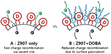 | ||
| Fig. 2 Illustration of TiO2 surface sensitized with Z907 (device-A), and Z907 + DOBA (device-B). | ||
Results and discussion
The extent of dye loading was examined by UV-Vis spectroscopy. The absorbances of electrode-A and electrode-B (1![[thin space (1/6-em)]](https://www.rsc.org/images/entities/char_2009.gif) :
:![[thin space (1/6-em)]](https://www.rsc.org/images/entities/char_2009.gif) 1 to 1
1 to 1![[thin space (1/6-em)]](https://www.rsc.org/images/entities/char_2009.gif) :
:![[thin space (1/6-em)]](https://www.rsc.org/images/entities/char_2009.gif) 5 ratio of Z907
5 ratio of Z907![[thin space (1/6-em)]](https://www.rsc.org/images/entities/b_char_2009.gif) :
:![[thin space (1/6-em)]](https://www.rsc.org/images/entities/b_char_2009.gif) DOBA) are shown in Fig. 3. The intensity was ca. 89% at a 1
DOBA) are shown in Fig. 3. The intensity was ca. 89% at a 1![[thin space (1/6-em)]](https://www.rsc.org/images/entities/char_2009.gif) :
:![[thin space (1/6-em)]](https://www.rsc.org/images/entities/char_2009.gif) 1 molar ratio of DOBA to Z907, indicating that the reactivity of the carboxylic acid in Z907, which anchored the compound onto the TiO2 surface, was higher than the reactivity of DOBA. The relative quantity of absorbed Z907 gradually decreased as the ratio of DOBA increased. This intensity reached 50% at a five-fold higher concentration (a molar ratio of 1
1 molar ratio of DOBA to Z907, indicating that the reactivity of the carboxylic acid in Z907, which anchored the compound onto the TiO2 surface, was higher than the reactivity of DOBA. The relative quantity of absorbed Z907 gradually decreased as the ratio of DOBA increased. This intensity reached 50% at a five-fold higher concentration (a molar ratio of 1![[thin space (1/6-em)]](https://www.rsc.org/images/entities/char_2009.gif) :
:![[thin space (1/6-em)]](https://www.rsc.org/images/entities/char_2009.gif) 5). These results suggested that DOBA effectively retarded the rate of dye adsorption due to the highly competitive anchoring process between the dye and the coadsorbent, as proposed previously.34 Therefore, Z907 was expected to be well-dispersed on the TiO2 surface, and the remaining empty sites were expected to be occupied by DOBA molecules.
5). These results suggested that DOBA effectively retarded the rate of dye adsorption due to the highly competitive anchoring process between the dye and the coadsorbent, as proposed previously.34 Therefore, Z907 was expected to be well-dispersed on the TiO2 surface, and the remaining empty sites were expected to be occupied by DOBA molecules.
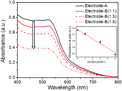 | ||
Fig. 3 (a) Absorbance spectra of electrode-A (Z907-coated TiO2, black line) and three electrodes (Z907+DOBA-coated TiO2) at various concentrations (1![[thin space (1/6-em)]](https://www.rsc.org/images/entities/char_2009.gif) : :![[thin space (1/6-em)]](https://www.rsc.org/images/entities/char_2009.gif) 1 Z907 1 Z907![[thin space (1/6-em)]](https://www.rsc.org/images/entities/b_char_2009.gif) : :![[thin space (1/6-em)]](https://www.rsc.org/images/entities/char_2009.gif) DOBA (—), 1 DOBA (—), 1![[thin space (1/6-em)]](https://www.rsc.org/images/entities/char_2009.gif) : :![[thin space (1/6-em)]](https://www.rsc.org/images/entities/char_2009.gif) 3 ( 3 (![[dash dash, graph caption]](https://www.rsc.org/images/entities/char_e091.gif) ), and 1 ), and 1![[thin space (1/6-em)]](https://www.rsc.org/images/entities/char_2009.gif) : :![[thin space (1/6-em)]](https://www.rsc.org/images/entities/char_2009.gif) 5 ( 5 (![[dash dot, graph caption]](https://www.rsc.org/images/entities/char_e090.gif) )). )). | ||
The relationship between the Z907 (or DOBA) content and the photovoltaic performances of device-A and devices-B prepared from the corresponding electrodes were investigated. A representative J–V curve is shown in Fig. 4. Device-A, employing only Z907, showed a JSC of 4.5 mA cm−2, a VOC of 684 mV, and a FF of 0.59, corresponding to an overall efficiency of 1.81%. Although we obtained a slightly lower value for the control device (device-A), these results were consistent with those of others, who reported a range of 1–3%27,33 under identical conditions. A low light harvesting efficiency (LHE) presents a major limitation to device performance. The LHE for sDSCs employing a thin TiO2 electrode is related to the light absorbance according to LHE = 1 − 10−A. Thus, it is possible that the low amounts of Z907 in electrodes-B reduced the performance of the electrode compared to electrode-A.
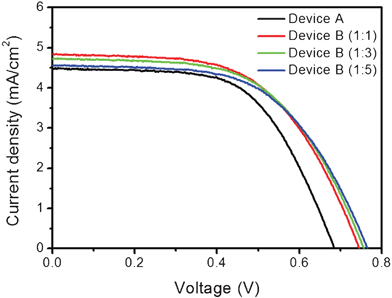 | ||
Fig. 4
J–V Characteristics of the devices used in this study: device A, sensitized with Z907 (black line); device B, co-sensitized with Z907/DOBA (red line) at various ratios (1![[thin space (1/6-em)]](https://www.rsc.org/images/entities/char_2009.gif) : :![[thin space (1/6-em)]](https://www.rsc.org/images/entities/char_2009.gif) 1 (red line), 1 1 (red line), 1![[thin space (1/6-em)]](https://www.rsc.org/images/entities/char_2009.gif) : :![[thin space (1/6-em)]](https://www.rsc.org/images/entities/char_2009.gif) 3 (green line), and 1 3 (green line), and 1![[thin space (1/6-em)]](https://www.rsc.org/images/entities/char_2009.gif) : :![[thin space (1/6-em)]](https://www.rsc.org/images/entities/char_2009.gif) 5 (blue line)). Masked active area of 0.16 cm2. Measured at the full-intensity sunlight irradiation using a 450 W Xenon lamp light source filtered to AM 1.5 conditions. 5 (blue line)). Masked active area of 0.16 cm2. Measured at the full-intensity sunlight irradiation using a 450 W Xenon lamp light source filtered to AM 1.5 conditions. | ||
The PCEs of device-B, however, were higher than those of device-A at all ratios, despite the lower degree of dye loading. The highest efficiency was achieved in device-B prepared from a solution containing a 1![[thin space (1/6-em)]](https://www.rsc.org/images/entities/char_2009.gif) :
:![[thin space (1/6-em)]](https://www.rsc.org/images/entities/char_2009.gif) 1 molar ratio of Z907
1 molar ratio of Z907![[thin space (1/6-em)]](https://www.rsc.org/images/entities/char_2009.gif) :
:![[thin space (1/6-em)]](https://www.rsc.org/images/entities/char_2009.gif) DOBA. JSC and VOC both increased, resulting in a 2.13% PCE, which was 18% higher than that of device-A. The efficiency gradually decreased as the ratio increased, as seen in device-B employing a 1
DOBA. JSC and VOC both increased, resulting in a 2.13% PCE, which was 18% higher than that of device-A. The efficiency gradually decreased as the ratio increased, as seen in device-B employing a 1![[thin space (1/6-em)]](https://www.rsc.org/images/entities/char_2009.gif) :
:![[thin space (1/6-em)]](https://www.rsc.org/images/entities/char_2009.gif) 5 ratio of Z907
5 ratio of Z907![[thin space (1/6-em)]](https://www.rsc.org/images/entities/char_2009.gif) :
:![[thin space (1/6-em)]](https://www.rsc.org/images/entities/char_2009.gif) DOBA. The JSC of device-B (1
DOBA. The JSC of device-B (1![[thin space (1/6-em)]](https://www.rsc.org/images/entities/char_2009.gif) :
:![[thin space (1/6-em)]](https://www.rsc.org/images/entities/char_2009.gif) 5) was 0.1 mA cm−2 higher than in device-A, even though the amount of dye was half that of device-A, indicating that light harvesting by the sensitizers may not be the limiting factor in device performance. As shown in Fig. 5, the harvesting ability of the dyes, which could be obtained by dividing the PCE (or JSC) by the dye loading, greatly increased with increasing DOBA content. The enhanced performance of device-B was due to several effects. In principle, the photocurrent is governed by light harvesting efficiency, electron injection yield, and charge collection efficiency as the following equation: JSC = ηLHE × ηinj × ηcoll. The light harvesting efficiency, as explained previously, is not a limiting factor for these experiments. In terms of electron injection, we reported recently that photocurrent could be enhanced by co-grafting organic molecules along with the N719 dye, which reduced dye aggregation and increased the electron injection efficiency.34 However, an increase in VOC could not be rationalized from a lack of dye aggregation in this case. Furthermore, the increase in VOC which is not only an indirect indication of the position of conduction band of TiO2 in a negative way but also the reduction of driving forces for electron injection (ΔGinj), does not follow the trend in JSC. A more plausible explanation is that charge recombination was retarded more effectively in device-B than in device-A. The organic molecules probably acted as an efficient passivation layer, thus formed an interlayer between the surface of TiO2 and HTM layer, by imposing a potential barrier to recombination through the increased hydrophobicity of the TiO2 surface. In other words, 51% of photoinduced electrons are dissipated by charge recombination when only Z907 is anchored on the surface of TiO2 compared to Z907 and DOBA (1
5) was 0.1 mA cm−2 higher than in device-A, even though the amount of dye was half that of device-A, indicating that light harvesting by the sensitizers may not be the limiting factor in device performance. As shown in Fig. 5, the harvesting ability of the dyes, which could be obtained by dividing the PCE (or JSC) by the dye loading, greatly increased with increasing DOBA content. The enhanced performance of device-B was due to several effects. In principle, the photocurrent is governed by light harvesting efficiency, electron injection yield, and charge collection efficiency as the following equation: JSC = ηLHE × ηinj × ηcoll. The light harvesting efficiency, as explained previously, is not a limiting factor for these experiments. In terms of electron injection, we reported recently that photocurrent could be enhanced by co-grafting organic molecules along with the N719 dye, which reduced dye aggregation and increased the electron injection efficiency.34 However, an increase in VOC could not be rationalized from a lack of dye aggregation in this case. Furthermore, the increase in VOC which is not only an indirect indication of the position of conduction band of TiO2 in a negative way but also the reduction of driving forces for electron injection (ΔGinj), does not follow the trend in JSC. A more plausible explanation is that charge recombination was retarded more effectively in device-B than in device-A. The organic molecules probably acted as an efficient passivation layer, thus formed an interlayer between the surface of TiO2 and HTM layer, by imposing a potential barrier to recombination through the increased hydrophobicity of the TiO2 surface. In other words, 51% of photoinduced electrons are dissipated by charge recombination when only Z907 is anchored on the surface of TiO2 compared to Z907 and DOBA (1![[thin space (1/6-em)]](https://www.rsc.org/images/entities/char_2009.gif) :
:![[thin space (1/6-em)]](https://www.rsc.org/images/entities/char_2009.gif) 5) anchored together. The loss of photocurrent by charge recombination gradually decreased from 41% and 33% by increasing the molar ratio of Z907
5) anchored together. The loss of photocurrent by charge recombination gradually decreased from 41% and 33% by increasing the molar ratio of Z907![[thin space (1/6-em)]](https://www.rsc.org/images/entities/char_2009.gif) :
:![[thin space (1/6-em)]](https://www.rsc.org/images/entities/char_2009.gif) DOBA from 1
DOBA from 1![[thin space (1/6-em)]](https://www.rsc.org/images/entities/char_2009.gif) :
:![[thin space (1/6-em)]](https://www.rsc.org/images/entities/char_2009.gif) 1 to 1
1 to 1![[thin space (1/6-em)]](https://www.rsc.org/images/entities/char_2009.gif) :
:![[thin space (1/6-em)]](https://www.rsc.org/images/entities/char_2009.gif) 3, respectively. This result suggested that the dense monolayer formed by DOBA having three hydrophobic alkyl chains and Z907 induced an interlayer between the surface of TiO2 and Spiro-OMeTAD (HTM) layer, effectively preventing charge recombination between photoinduced electrons and cationic HTMs.
3, respectively. This result suggested that the dense monolayer formed by DOBA having three hydrophobic alkyl chains and Z907 induced an interlayer between the surface of TiO2 and Spiro-OMeTAD (HTM) layer, effectively preventing charge recombination between photoinduced electrons and cationic HTMs.
![PCE/[dye] (black column) and JSC/dye (red column) for varying [Z907] : [DOBA] ratios.](/image/article/2012/RA/c2ra01251k/c2ra01251k-f5.gif) | ||
Fig. 5 PCE/[dye] (black column) and JSC/dye (red column) for varying [Z907]![[thin space (1/6-em)]](https://www.rsc.org/images/entities/char_2009.gif) : :![[thin space (1/6-em)]](https://www.rsc.org/images/entities/char_2009.gif) [DOBA] ratios. [DOBA] ratios. | ||
The effects of DOBA on the interfacial properties were investigated by measuring the surface properties of electrode-A and electrode-B. Water contact angle (Θwater) measurements revealed the surface properties of TiO2. Θwater for the Z907-sensitized TiO2 (electrode-A) was 120° at 25 °C (Fig. 6(b)), which was about 108° larger than Θwater for bare TiO2 (Fig. 6(a)). This result indicated that the two alkyl chains in Z907 conveyed hydrophobic properties to the surface. In contrast, electrode-B yielded a Θwater of 132° (Fig. 6(c)), even though the Z907 content was 11% lower than on electrode-A, as shown in Fig. 3. These results indicated that coadsorption of Z907 with DOBA formed a monolayer that was denser than that formed by Z907 alone, thereby enhancing the hydrophobicity of the electrode-B surface. This result was ascribed to the number of alkyl groups and chain lengths (e.g., three dodecyl groups in DOBAvs. two octyl groups in Z907). The enhanced hydrophobicity of the TiO2 surface provided fewer opportunities for recombination between the photo-injected electrons and the holes. Furthermore, a spin-coating chlorobenzene solution spread easily and flowed through the three-dimensional porous network area of the electrode-B, thereby facilitating pore-filling.35 The wetting characteristics of the sensitized TiO2 film surfaces were useful indicators of device performance because they reflected the dye-sensitized electrode/HTM interfacial properties.
 | ||
| Fig. 6 Water contact angles on a screen-printed TiO2 surface: (a) on a bare TiO2 surface (12°), (b) on a TiO2 surface sensitized with Z907 (120°), and (c) on a TiO2 surface sensitized with Z907 and DOBA (132°). | ||
EIS measurements were conducted to improve our understanding of the effects of the hydrophobic DOBA coadsorbent on the device performance. The charge transfer rates at the interfaces of the dye-sensitized TiO2/HTM or the HTM/counter electrode (CE) were obtained from the EIS measurements.16,25 Recently, Bisquert et al. proposed a physical model of the complex charge transfer and transport processes occurring in DSCs.36Fig. 7(a), which shows the Nyquist plots of each device under a forward bias of −0.65 V, serves as an illustrative example of this conceptual model. Two distinct semicircles were observed in the Nyquist plot based on EIS measurements. The first semicircle, in the high-frequency range of the Nyquist plot, was related to the charge exchange processes at the HTM (spiro-MeOTAD)/CE (Au) interface. The low-frequency semicircle was related to recombination between electrons in the TiO2 conduction band and holes in the HTM at the TiO2/spiro-OMeTAD interface. The electron transport resistance through the TiO2 network (Rtrans) was not measured in this measurement. A transmission line model was fit to the impedance data to obtain the recombination resistance (Rct) and the electron lifetime (τe). As shown in Fig. 7(b) and 7(c), the recombination resistance of device-B (1![[thin space (1/6-em)]](https://www.rsc.org/images/entities/char_2009.gif) :
:![[thin space (1/6-em)]](https://www.rsc.org/images/entities/char_2009.gif) 1) is one order of magnitude larger than that of device-A over all ranges under a −0.4 V to −0.7 V forward bias. The electron lifetimes were longer in device-B (1
1) is one order of magnitude larger than that of device-A over all ranges under a −0.4 V to −0.7 V forward bias. The electron lifetimes were longer in device-B (1![[thin space (1/6-em)]](https://www.rsc.org/images/entities/char_2009.gif) :
:![[thin space (1/6-em)]](https://www.rsc.org/images/entities/char_2009.gif) 1) than in device-A, indicating the extent of DOBA surface passivation due to the interlayer formed by DOBA.
1) than in device-A, indicating the extent of DOBA surface passivation due to the interlayer formed by DOBA.
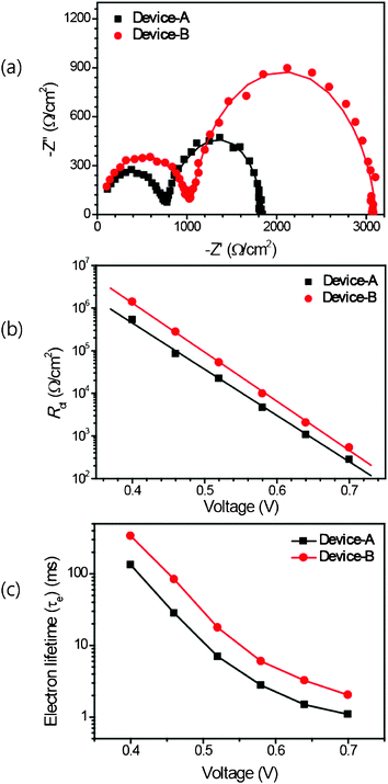 | ||
Fig. 7 (a) Nyquist plots for the solid state DSCs device-A (black line) and device-B (1![[thin space (1/6-em)]](https://www.rsc.org/images/entities/char_2009.gif) : :![[thin space (1/6-em)]](https://www.rsc.org/images/entities/char_2009.gif) 1) (red line), under a forward bias of −0.65 V under dark conditions. The solid line corresponds to the values derived using the fitting model. (b) The recombination resistance (Rct) as a function of the applied bias voltage obtained from impedance measurements in the dark for device-A (black line) and device-B (1 1) (red line), under a forward bias of −0.65 V under dark conditions. The solid line corresponds to the values derived using the fitting model. (b) The recombination resistance (Rct) as a function of the applied bias voltage obtained from impedance measurements in the dark for device-A (black line) and device-B (1![[thin space (1/6-em)]](https://www.rsc.org/images/entities/char_2009.gif) : :![[thin space (1/6-em)]](https://www.rsc.org/images/entities/char_2009.gif) 1) (red line). (c) Estimated electron lifetimes (τe) for device-A (black line) and device-B (1 1) (red line). (c) Estimated electron lifetimes (τe) for device-A (black line) and device-B (1![[thin space (1/6-em)]](https://www.rsc.org/images/entities/char_2009.gif) : :![[thin space (1/6-em)]](https://www.rsc.org/images/entities/char_2009.gif) 1) (red line) using the equation τe = 1/2πf, where the f is the frequency at the maximum in the Nyquist plot. 1) (red line) using the equation τe = 1/2πf, where the f is the frequency at the maximum in the Nyquist plot. | ||
The interfacial characteristics of DSCs were conveniently assessed using optical impedance techniques, such as IMPS/IMVS.37 The IMPS provided information about the electron transit (transport) time (τtrans) through the nanocrystalline TiO2 to the photoanode under short-circuit conditions, and the IMVS measured the recombination lifetime (τe) of the photo-injected electrons, which recombined with the holes in the HTM or oxidized dyes under open-circuit conditions. Fig. 8 shows the results of the IMPS and IMVS measurements at various light intensities. The transport times (τtrans) in the two devices were nearly identical, which was not surprising because the electrodes were fabricated under identical conditions, including TiO2 deposition and film thickness. The electron lifetime (τe) of device-B (1![[thin space (1/6-em)]](https://www.rsc.org/images/entities/char_2009.gif) :
:![[thin space (1/6-em)]](https://www.rsc.org/images/entities/char_2009.gif) 1), however, was longer than that of device-A, which was consistent with the results of the EIS measurements. A longer τe suggests a lower chance of successful charge recombination, thereby reducing loss and enhancing the photocurrent and photovoltage.
1), however, was longer than that of device-A, which was consistent with the results of the EIS measurements. A longer τe suggests a lower chance of successful charge recombination, thereby reducing loss and enhancing the photocurrent and photovoltage.
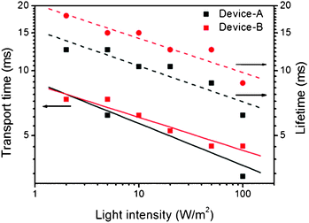 | ||
Fig. 8 Electron transport times (τtrans, solid line) and electron lifetimes (τe, dashed line) for device-A (black) and device-B (1![[thin space (1/6-em)]](https://www.rsc.org/images/entities/char_2009.gif) : :![[thin space (1/6-em)]](https://www.rsc.org/images/entities/char_2009.gif) 1) (red), from IMPS/IMVS measurements. 1) (red), from IMPS/IMVS measurements. | ||
Apart from the higher photocurrents generated by device-B, VOC was 60 mV larger than that of device-A. The changes in VOC and the trapping states induced by the presence of DOBA were investigated by cyclic voltammetry. Experiments were performed on each TiO2electrode-A and electrode-B (1![[thin space (1/6-em)]](https://www.rsc.org/images/entities/char_2009.gif) :
:![[thin space (1/6-em)]](https://www.rsc.org/images/entities/char_2009.gif) 1) in the ionic liquid 1-butyl-3-methylimidazolium bromide (BMIB). The capacitive currents of the electrodes revealed gradual onsets under a forward bias. As shown in Fig. 9, the onset was around −0.38 V (vs. Ag/AgCl) for electrode-A, whereas electrode-B (1
1) in the ionic liquid 1-butyl-3-methylimidazolium bromide (BMIB). The capacitive currents of the electrodes revealed gradual onsets under a forward bias. As shown in Fig. 9, the onset was around −0.38 V (vs. Ag/AgCl) for electrode-A, whereas electrode-B (1![[thin space (1/6-em)]](https://www.rsc.org/images/entities/char_2009.gif) :
:![[thin space (1/6-em)]](https://www.rsc.org/images/entities/char_2009.gif) 1) displayed an onset at −0.49 V, indicating a negative shift in the conduction band of the TiO2. Furthermore, the total injected charge (Q) of electrode-B (1
1) displayed an onset at −0.49 V, indicating a negative shift in the conduction band of the TiO2. Furthermore, the total injected charge (Q) of electrode-B (1![[thin space (1/6-em)]](https://www.rsc.org/images/entities/char_2009.gif) :
:![[thin space (1/6-em)]](https://www.rsc.org/images/entities/char_2009.gif) 1) increased more slowly than in electrode-A due to better surface passivation by DOBA.
1) increased more slowly than in electrode-A due to better surface passivation by DOBA.
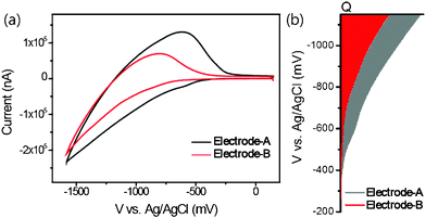 | ||
Fig. 9 (a) Cyclic voltammograms for electrode-A (black line) and electrode-B (1![[thin space (1/6-em)]](https://www.rsc.org/images/entities/char_2009.gif) : :![[thin space (1/6-em)]](https://www.rsc.org/images/entities/char_2009.gif) 1) (red line), and (b) energy levels in the mesoscopic TiO2. 1) (red line), and (b) energy levels in the mesoscopic TiO2. | ||
Conclusion
In the present study, we successful introduced an interlayer between HTM layer and the surface of TiO2 using DOBA having three hydrophobic alkyl chains. This interlayer effectively prevented charge recombination between photoinduced electrons and cationic HTMs, resulting in efficient solid-state dye-sensitized solar cells. The hydrophobic dendron-based organic molecules, DOBA, expedited not only the formation of compact monolayer on the surface of TiO2 but also reduced the chances for electrons in TiO2 recombining with holes in spiro-OMeTAD. As a result, 51% of losses in photocurrent by charge recombination for Z907-sensitized solar cells were prevented by the interlayer. Furthermore, DOBA induced the negative shift of the conduction band of TiO2, resulting in higher open circuit voltage.Acknowledgements
This work was supported by a grant (M2009010025) from the Fundamental R&D Program for Core Technology of Materials, funded by the MKE, by the Mid-career Researcher Program and Future-based Technology Development Program (Nano Fields) through NRF, funded by the MEST (No. 2010-0000406, No. 2010-0019119), and by the second stage of a BK21 (Brain Korea 21) grant.References
- B. O'Regan and M. Grätzel, Nature, 1991, 353, 737 CrossRef CAS.
- M. K. Nazeeruddin, F. De Angelis, S. Fantacci, A. Selloni, G. Viscardi, P. Liska, S. Ito, B. Takeru and M. Grätzel, J. Am. Chem. Soc., 2005, 127, 16835 CrossRef CAS.
- Y. Chiba, A. Islam, Y. Watanabe, R. Komiya, N. Koide and L. Han, Jpn. J. Appl. Phys., 2006, 45, L638 CrossRef CAS.
- H. J. Snaith and L. Schmidt-Mende, Adv. Mater., 2007, 19, 3187 CrossRef CAS.
- U. Bach, D. Lupo, P. Comte, J. E. Moser, F. Weissortel, J. Salbeck, H. Spreitzer and M. Grätzel, Nature, 1998, 395, 583 CrossRef CAS.
- J. Xia, N. Masaki, M. Lira-Cantu, Y. Kim, K. Jiang and S. Yanadiga, J. Am. Chem. Soc., 2008, 130, 1258 CrossRef CAS.
- I. Y. Song, S. -H. Park, J. Lim, Y. S. Kwon and T. Park, Chem. Commun., 2011, 47, 10395 RSC.
- D. Poplavskyy and J. Nelson, J. Appl. Phys., 2003, 93, 341 CrossRef CAS.
- L. Schmidt-Mende and M. Grätzel, Thin Solid Films, 2006, 500, 296 CrossRef CAS.
- U. B. Cappel, M. H. Karlsson, N. G. Pschirer, F. Eickemeyer, J. Schöneboom, P. Erk, G. Boschloo and A. Hagfeldt, J. Phys. Chem. C, 2009, 113, 14595 CAS.
- P. Chen, P. J.-H. Yum, F. De Angelis, E. Mosconi, S. Fantacci, S.-J. Moon, R. H. Baker, J. Ko, M. K. Nazeeruddin and M. Grätzel, Nano Lett., 2009, 9, 2487–2492 CrossRef CAS.
- I.-K. Ding, N. Tétreault, J. Brillet, B. E. Hardin, E. H. Smith, S. J. Rosenthal, F. Sauvage, M. Grätzel and M. D. McGehee, Adv. Funct. Mater., 2009, 19, 2431 CrossRef CAS.
- W. H. Howie, F. Claeyssens, H. Miura and L. M. Peter, J. Am. Chem. Soc., 2008, 130, 1367 CrossRef CAS.
- J. E. Kroeze, N. Hirata, L. Schmidt-Mende, C. Orizu, S. D. Ogier, K. Carr, M. Grätzel and J. R. Durrant, Adv. Funct. Mater., 2006, 16, 1832 CrossRef CAS.
- S.-J. Moon, J-H. Yum, R. Humphry-Baker, K. M. Karlsson, D. P. Hagberg, T. Marinado, A. Hagfeldt, L. Sun, M. Grätzel and M. K. Nazeeruddin, J. Phys. Chem. C, 2009, 113, 16816 CAS.
- L. Schmidt-Mende, U. Bach, R. Humphry-Baker, T. Horiuchi, H. Miura, S. Ito, S. Uchida and M. Grätzel, Adv. Mater., 2005, 17, 813 CrossRef CAS.
- H. J. Snaith, A. J. Moule, C. Klein, K. Meerholz, R. H. Friend and M. Grätzel, Nano Lett., 2007, 7, 3372 CrossRef CAS.
- L. Schmidt-Mende, S. M. Zakeeruddin and M. Grätzel, Appl. Phys. Lett., 2005, 86, 013504–1 CrossRef.
- S. Ito, T. N. Murakami, P. Comte, P. Liska, C. Grätzel, M. K. Nazeeruddin and M. Grätzel, Thin Solid Films, 2008, 516, 4613 CrossRef CAS.
- F. Fabregat-Santiago, J. Bisquert, L. Cevey, P. Chen, M. Wang, S. M. Zakeeruddin and M. Grätzel, J. Am. Chem. Soc., 2009, 131, 558 CrossRef CAS.
- D. Kuang, C. Klein, H. J. Snaith, J. E. Moser, R. Humphry-Baker, P. Comte, S. M. Zakeeruddin and M. Grätzel, Nano Lett., 2006, 6, 769 CrossRef CAS.
- S. A. Hague, T. Park, C. Xu, S. Koops, N. Schulte, R. J. Potter, A. B. Holmes and J. R. Durrant, Adv. Funct. Mater., 2004, 14, 435 CrossRef.
- T. Park, S. A. Haque, R. J. Potter, A. B. Holmes and J. R. Durrant, Chem. Commun., 2003, 9, 2878 RSC.
- J. Krüger, R. Plass, L. Cevey, M. Piccirelli, M. Grätzel and U. Bach, Appl. Phys. Lett., 2001, 79, 2085 CrossRef.
- T. C. Li, M. S. Góes, F. Fabregat-Santiago, J. Bisquert, P. R. Bueno, C. Praslttichal, J. T. Hupp and T. J. Marks, J. Phys. Chem. C, 2009, 113, 18385 CAS.
- T. Taguchi, X. T. Zhang, I. Sutanto, K. I. Tokuhiro, T. N. Rao, H. Watanabe, T. Nakamori, M. Uragam and A. Fujishima, Chem. Commun., 2003, 9, 2480 RSC.
- (a) M. Wang, C. Grätzel, S. -J. Moon, R. Humphry-Baker, N. Rossier-Iten, S. M. Zakeeruddin and M. Grätzel, Adv. Funct. Mater., 2009, 19, 2163 CrossRef CAS; (b) S.-H. Park, J. Lim, I. Y. Song, N. Atmakuri, S. Song, Y. S. Kwon, J. M. Choi and T. Park, Adv. Energy Mater., 2012, 2, 219 CrossRef.
- N. R. Neale, N. Kopidakis, J. Van De Lagemaat, M. Grätzel and A. J. Frank, J. Phys. Chem. B, 2005, 109, 23183 CrossRef CAS.
- M. Wang, X. Li, H. Lin, P. Pechy, S. M. Zakeeruddin and M. Grätzel, Dalton Trans., 2009, 10015 RSC.
- X. Zeng, L. Cseh, G. H. Mehl and G. Ungar, J. Mater. Chem., 2008, 18, 2953 RSC.
- L. Kavan and M. Grätzel, Electrochim. Acta, 1995, 40, 643 CrossRef CAS.
- T. Park, Ph. D. Thesis, University of Cambridge, 2004 Search PubMed.
- P. Tiwana, P. Parkinson, M. B. Johnston, H. J. Snaith and L. M. Herz, J. Phys. Chem. C, 2010, 114, 1365 CAS.
- (a) J. Lim, Y. S. Kwon and T. Park, Chem. Commun., 2011, 47, 4147 RSC; (b) J. Lim, Y. S. Kwon, S.-H. Park, I. Y. Song, J. Choi and T. Park, Langmuir, 2011, 27, 14647 CrossRef CAS.
- M. Wang, S. -J. Moon, D. Zhou, F. Le Formal, N. -L. Cevey-Ha, R. Humphry-Baker, C. Grätzel, P. Wang, S. M. Zakeeruddin and M. Grätzel, Adv. Funct. Mater., 2010, 20, 1 Search PubMed.
- J. Bisquert, D. Cahen, G. Hodes, S. Rühle and A. Zaban, J. Phys. Chem. B, 2004, 108, 8106 CrossRef CAS.
- J. R. Jennings and L. M. Peter, J. Phys. Chem. C, 2007, 111, 16100 CAS.
Footnote |
| † Present address: Department of Inorganic Chemistry, School of Chemistry, Madurai Kamaraj University, Palkalai Nagar, Madurai 625 021, Tamilnadu, India. |
| This journal is © The Royal Society of Chemistry 2012 |
