An all perovskite direct methanol solid oxide fuel cell with high resistance to carbon formation at the anode
Hongjiao
Li
,
Ye
Tian
,
Zhiming
Wang
,
Fuchang
Qie
and
Yongdan
Li
*
Tianjin Key Laboratory of Applied Catalysis Science and Technology and State Key Laboratory of Chemical Engineering (Tianjin University), School of Chemical Engineering, Tianjin University, Tianjin 300072, China. E-mail: ydli@tju.edu.cn; Fax: +86-22-27405243; Tel: +86-22-27405613
First published on 12th March 2012
Abstract
A chemically stable perovskite material Sr2Fe1.5Mo0.5O6 (SFMO) is employed as the anode of a solid oxide fuel cell (SOFC). An electrolyte-supported single cell with anode, electrolyte and cathode all made of perovskite structured materials and with a configuration of SFMO|La0.8Sr0.2Ga0.83Mg0.17O3|Ba0.5Sr0.5Co0.8Fe0.2O3 (SFM|LSGM|BSCF) is fabricated by a screen printing method. The single cell gives a maximum power density of 391 mW cm−2 for CH3OH, and 520 mW cm−2 for H2 as the fuel, respectively, at 1073 K with oxygen as the oxidant gas. The mass spectra of the flue gas out of the test reactor confirm that methanol thermally decomposes inside the anode chamber and generates mainly CO and H2 at 1023 K. Analysis of the after-test cell tells that the anode surface has no carbon formation under reaction with methanol as the feed for 3 h. The carbon resistance is attributed to the fact that the anode is in oxide state which cannot facilitate the formation of bulk carbon with graphite structure. The fast activation and gasification of the carbon species by the oxidative atmosphere around the anode surface are also beneficial factors. The test results indicate also that the activation of CH3OH is much more difficult than that of H2.
1. Introduction
The direct electrochemical-oxidation of carbon-containing fuels in a solid oxide fuel cell (SOFC) has been a great challenge because of the high tendency of carbon deposition on the anode surface.1–3 Carbon deposition on the anode leads to the coverage of the active sites, blockage of the pores and destruction of the microstructure, which ends the lifetime of the SOFC.4 It has been well known that the carbon-containing fuels have a large thermodynamic potential for coke formation in many catalytic processes.5,6 However, the formation of bulk phase carbon is only kinetically favored when suitable catalytic sites exist. Metal catalysts often facilitate fibrous carbon formation.7,8 In the direct carbon-containing fuel electrochemical-oxidization SOFCs, metals or reducible metallic oxides have often been employed as the catalytic component of the anode composite material. As a consequence, coking at the anode has been a major obstacle for the commercial application of SOFCs.9,10Methanol as a fuel is carbon dioxide neutral, renewable and sustainable if produced from biomass or from a solar-energy powered catalytic process.11,12 In a liquid state at ambient conditions, methanol is of high energy density so that greatly eases the effort for storage, transportation and distribution.10–13 Furthermore, methanol as a readily available and low cost oil processing product, has been investigated extensively in reforming reactions and it is commonly considered that it is more active than the most of the other carbon-containing fuels benefiting a desired intermediate-temperature operation.14–17
Under the direct feed of a dry carbon-containing fuel, an ideal anode catalytic material should be highly active for the catalytic dissociation of the fuel molecule and highly suppressive for C–C formation as well as highly inductive for producing CO and CO2.18 A metallic Ni-based anode fails due to its high activity for the formation of C–C bonds and graphite structured carbon fibers and tubes. Nevertheless, nano-sized Ni particles have a better tolerance to coking and highly dispersed Ni on perovskite has shown a good performance.19 Perovskite materials also share a prominent anti-coking capability in the methane and ethanol steam reforming reactions.20–23 Perovskite has a cubic unit cell with A ions at the body center, B ions at the corners and oxygen ions at the center of the faces. In the perovskite structure, the A cation is coordinated with twelve oxygen ions and the B cation with six. The perovskite has a moderate activity towards the activation of carbon-containing fuels and is carbon-resistive because graphitic carbon formation needs an ensemble of several metal atoms at the catalytic site.4 Huang et al.2 reported that perovskite Sr2Mg1−xMnxMoO6−δ as an SOFC anode has a long-term stability with tolerance to sulfur. They got a single-cell performance with a maximum power density of 438 mW cm−2 with dry methane as the feed at 1073 K with an electrolyte of 300-μm-thick La0.8Sr0.2Ga0.83Mg0.17O3 (LSGM).2 Wang et al.24 employed Sr2FeMoO6 as the anode and got a maximum power density of 605 mW cm−2 with dry methane as the fuel at 1123 K. However, this material has to be synthesized in a H2 atmosphere and reduced for 5 h at 1023 K before testing. Sr2Fe1.5Mo0.5O6 (SFMO) is stable in an oxidative atmosphere and has been employed as the electrodes in a symmetrical SOFC and as the cathode in a normal SOFC.25,26 SFMO has high ionic and electronic conductivity as well as high oxygen surface exchange and diffusion constants.25,27 Based on the existing data, it is assumed that SFMO can be a good material for the anode of the direct methanol fuel cell due to its ability to dissociate hydrocarbons and fast transfer of oxygen ions from the bulk to the surface.
Herein, we report for the first time a SOFC, with SFMO as the anode, for directly utilizing methanol as the fuel and compare the performance with that of hydrogen. Efforts are made to illuminate how the methanol reacts on the perovskite anode in the SOFC.
2. Experimental
SFMO powder was synthesized by a solid-state reaction. Stoichiometric SrCO3, Fe2O3 and MoO3 were thoroughly mixed with an agate mortar and then calcined at 1173 K for 10 h. The calcined powder was pelletized at 200 MPa and annealed at 1523 K in air for 5 h to obtain a pure perovskite structure. For XRD measurement, the pellets were ground and ball milled into very fine powders. The XRD patterns of the fresh sample and the reduced one, in H2 at 1273 K for 5 h, were recorded at room temperature using a D/max 2500 v/pc instrument (Rigaku Corp. Japan) with Cu-Kα radiation, 40 kV and 200 mA, at a scanning rate of 5° min−1. The surface properties of the fresh and the after-test SFMO were tested by a PHI 1600 X-ray photoelectron spectroscopy (XPS) system with Mg-Kα radiation. The preparations of Ba0.5Sr0.5Co0.8Fe0.2O3 (BSCF) cathode and LSGM electrolyte materials have been described elsewhere.28,29The electrolyte-supported single cell was fabricated by a screen-printing technique. LSGM powder was pressed to a pellet under 200 MPa and sintered at 1723 K for 20 h to the dense state with a thickness of 300 μm. SFMO and BSCF were both mixed with a binder (V006, Heraeus Ltd.) to make into slurries. The SFMO slurry was firstly coated on one side of the electrolyte and sintered at 1423 K in air for 1 h. The BSCF slurry was then screen-printed on the other side of the electrolyte and sintered at 1273 K in air for 1 h. Ag paste was coated on both sides to function as the current collector.
A home-made setup was employed for the performance test of the single cell at 1023 K and 1073 K under atmosphere. Liquid methanol is gasified at 423 K before being fed into the anode. The hydrogen or pure methanol stream, with a flow rate of equivalent 80 ml min−1, passed through an alumina tube to reach the anode chamber. Pure oxygen fed the cathode chamber with a flow rate of 100 ml min−1. The cell was operated so that H2 firstly was fed as the fuel and then the feed switched to methanol after all tests of H2 were done. To test the decomposition of methanol at the inlet channel and anode chamber, mass spectra of the after-condensed outlet flue gases of the test reactor are recorded for the cell with and without the anode by a Hiden Analytical Instrument MS. The I–V characteristics of the single cell were measured by an IT-30 electronic load made by Ningbo BaTe Technology Co., Ltd., China. The impedance spectra of the single cell at open circuit (OC) conditions were recorded with an Ametek Electrochemical Work Station. The SEM images and EDX of the anode surface before and after test were obtained with a Genesis XM2 instrument to reflect any change induced by the methanol feed.
3. Results and discussion
3.1. Characterization
Fig. 1 depicts the XRD patterns of the fresh SFMO and the one reduced under H2 at 1223 K for 5 h. Both the fresh and the reduced SFMO samples display clearly and identically a pure-perovskite structure with only small shifts of the peak positions for the two samples. SFMO has a cubic crystal structure, with a lattice constant a equalling 0.7851 nm and 0.7859 nm for the fresh sample and the reduced one, respectively. The lattice constants here are calculated with an XRD analysis software, i.e., Jade. It can be remarked that the SFMO structure is stable both in oxidative and reductive atmospheres. The results agree with those reported by Liu et al.28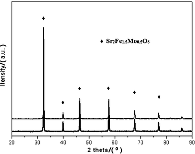 | ||
| Fig. 1 XRD patterns of (upper line) fresh SFMO and (lower line) reduced SFMO in H2 at 1273 K for 5 h. | ||
Fig. 2 shows the chemical states of Fe and Mo elements in the fresh and after-test SFMO by the Fe-2p and Mo-3d core-level spectra, the atom ratios for each element are summarized in Table 1. Metals such as Fe or Mo did not appear. The results showed a slight change in the atomic ratios of different species, i.e., an increase in Fe3+ and Mo5+, and a decrease in Fe2+ and Mo6+. This slight difference is assumed to be caused by the electro-oxidation reactions, but further verification on this difference need to be done. XPS results further confirm that this material is chemically stable under the operation conditions. This property promises the redox-stability of the anode and easy treatment during the fabrication of the cell. It has been reported that, since the Mo5+/Mo6+ redox band overlapped with the Fe3+/Fe2+ couple, the Fe3+ survived consequently from being fully reduced in the perovskite structure.29 Unlike Sr2FeMoO6 which is famous for its magnetoresistance property with an almost regular arrangement of Fe and Mo atoms at B sites, the prepared SFMO in this work may have a much more random arrangement of B site metal ions due to the inequality of the metal ratios.30,31 Analysis of the XPS indicates that the theoretical stoichiometries of oxygen is 5.977 and 5.98 for the fresh and the after-test SFMO respectively, thus it can be concluded that there exist substantial oxygen vacancies in the SFMO lattice, promising a good oxygen ionic conductivity. The electronic conductivity of SFMO is reported to be high both in air and hydrogen atmospheres and it is expected that the large iron content in this material permits the formation of Fe–O–Fe bonds as the pathways for the movement of electrons or electron holes.29 In summary, the co-existence of Fe3+–Mo5+, Fe2+–Mo6+ pairs in the SFMO structure results in a rich oxygen vacancy as well as an excellent electronic conductivity.
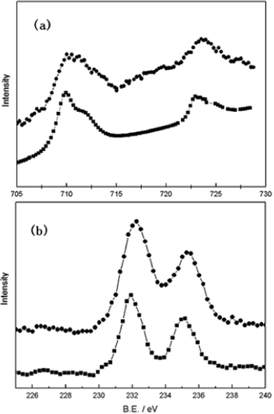 | ||
| Fig. 2 (a) Fe-2p and (b) Mo-3d core-level spectra of SFMO at room temperature. (⁃•⁃): before-test; (⁃■⁃) after-test. | ||
| Fe2+ | Fe3+ | Mo5+ | Mo6+ | |
|---|---|---|---|---|
| Fresh SFMO | 0.539 | 0.461 | 0.507 | 0.493 |
| After-test SFM | 0.497 | 0.503 | 0.543 | 0.457 |
3.2. Performance
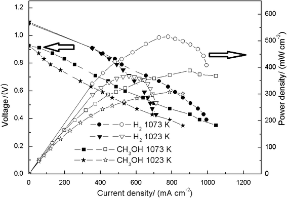 | ||
| Fig. 3 Performance of the built single cell. The measurement starts form OCP and each discharging potential is kept for 20 s to obtain the steady output parameters. | ||
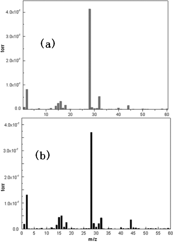 | ||
| Fig. 4 Mass spectra of the after-condensed anode side flue gas coming out of the reactor. (a) the cell without the anode in the reactor; (b) complete single cell in the reactor. The main fragments appearing in the Figure are: H (m/z = 1), H2 (m/z = 2), CH2 (m/z = 14), CH3 (m/z = 15), O (m/z = 16), OH (m/z = 17), H2O (m/z = 18), CO (m/z = 28), CH3OH (m/z = 32), CO2 (m/z = 44). | ||
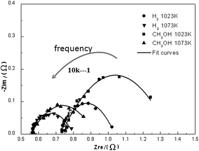 | ||
| Fig. 5 Impedance spectra of the single cell using H2 and CH3OH as the fuels under OC state at 1023 K and 1073 K. The intersections of the impedance curves and the x-axis at low and high frequencies are attributed to the electrolyte and total resistances, respectively. The electrolyte resistances at 1023 K and 1073 K are 0.57 Ω and 0.74 Ω, respectively. | ||
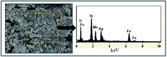 | ||
| Fig. 6 EDX scanning of the after-test anode surface; the right Figure indicates there is no carbon element in the anode material. | ||
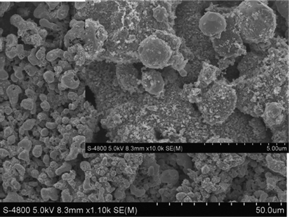 | ||
| Fig. 7 SEM images of the after-test anode surface; the morphology shows no carbon fiber or carbon whiskers attached to the anode material. | ||
4. Conclusion
The SFMO material prepared by the solid-state reaction technique shows an excellent chemical stability under both oxidative and reductive atmospheres. Employing SFMO as the anode, a SOFC with the direct electrochemical oxidation of methanol, gave promising power densities, i.e. 308 mW cm−2 and 391 mW cm−2 at 1023 K and 1073 K, respectively. Impedance spectra with I–V curves of the single cell indict that the activation of methanol is much more difficult than that of hydrogen. A number of different measurements clearly confirmed that the anode survived from carbon formation. This result of carbon resistance as well as activity towards electro-oxidation of the fuel promises a reasonable application of SFMO as catalysts for the direct electrochemical oxidation of carbon-containing fuels.Acknowledgements
The financial support of NSF of China under contract numbers 21076150 and 21120102039 is gratefully acknowledged. The work has been also supported in part by the Program of Introducing Talents to the University Disciplines under file number B06006, and the Program for Changjiang Scholars and Innovative Research Teams in Universities under file number IRT 0641.References
- S. Tao and J. T. S. Irvine, Nat. Mater., 2003, 2, 320–323 CrossRef CAS.
- J. B. Goodenough, Y. H. Huang, R. I. Dass and Z. L. Xing, Science, 2006, 312, 254–257 CrossRef.
- E. P. Murray, T. Tsai and S. A. Barnett, Nature, 1999, 400, 649–651 CrossRef CAS.
- C. H. Bartholomew, Catal. Rev. Sci. Eng., 1982, 24, 67–112 CAS.
- D. L. Trimm, Catal. Today, 1999, 49, 3–10 CrossRef CAS.
- J. Barbier, Appl. Catal., 1986, 23, 225–243 CrossRef CAS.
- L. Yang, S. Z. Wang, K. Blinn, M. F. Liu, Z. liu, Z. Cheng and M. L. Liu, Science, 2009, 326, 126–129 CrossRef CAS.
- Y. D. Li, D. X. Li and G. W. Wang, Catal. Today, 2011, 162, 1–48 CrossRef CAS.
- R. M. Ormerod, Chem. Soc. Rev., 2003, 32, 17–28 RSC.
- S. McIntosh and R. J. Gorte, Chem. Rev., 2004, 104, 4845–4865 CrossRef CAS.
- M. Gattrell, N. Gupta and A. Co, Energy Convers. Manage., 2007, 48, 1255–1265 CrossRef CAS.
- M. E. Himmel, S. Y. Ding, D. K. Johnson, W. S. Adney, M. R. Nimlos, J. W. Brady and T. D. Foust, Science, 2007, 315, 804–807 CrossRef CAS.
- J. Xuan, M. K. H. Leung, D. Y. C. Leung and M. Ni, Renewable Sustainable Energy Rev., 2009, 13, 1301–1313 CrossRef CAS.
- J. M. Ogden, M. M. Steinbugler and T. G. Kreutz, J. Power Sources, 1999, 79, 143–168 CrossRef CAS.
- S. Assabumrungrat, N. Laosiripojana, V. Pavarajarn, W. Sangtongkitcharoen, A. Tangjitmatee and P. Praserthdam, J. Power Sources, 2005, 139, 55–60 CrossRef CAS.
- D. Cocco and V. Tola, Proceedings of the ASME Turbo Expo, 2006, 4(2006), 257–266 Search PubMed.
- D. Cocco and V. Tola, Proceedings of the 8th Biennial Conference on Engineering Systems Design and Analysis, 2006, 1, 137–147 Search PubMed.
- E. Nikolla, A. Holewinski, J. Schwank and S. Linic, J. Am. Chem. Soc., 2006, 128, 11354–11355 CrossRef CAS.
- V. Sadykov, N. Mezentseva, G. Alikina, R. Bunina, V. Pelipenko, A. Lukashevich, S. Tikhov, V. Usoltsev, Z. Vostrikov, O. Bobrenok, A. Smirnova, J. Ross, O. Smorygo and B. Rietveld, Catal. Today, 2009, 146, 132–140 CrossRef CAS.
- A. L. Sauvet, J. Fouletier, F. Gaillard and M. Primet, J. Catal., 2002, 209, 25–34 CrossRef CAS.
- P. Vernoux, E. Djurado and M. Guillodo, J. Am. Ceram. Soc., 2001, 84, 2289–2295 CrossRef CAS.
- J. Akikusa, K. Adachi, K. Hoshino, T. Ishihara and Y. Takita, J. Electrochem. Soc., 2001, 148, A1275–A1278 CrossRef CAS.
- S. Q. Chen, Y. D. Li, Y. Liu and X. Bai, Int. J. Hydrogen Energy, 2011, 36, 5849–5856 CrossRef CAS.
- Z. M. Wang, Y. Tian and Y. D. Li, J. Power Sources, 2011, 196, 6104–6109 CrossRef CAS.
- L. Zhang, Y. Liu, Y. Zhang, G. Xiao, F. Chen and C. Xia, Electrochem. Commun., 2011, 13, 711–713 CrossRef CAS.
- G. Xiao, Q. Liu, X. Dong, K. Huang and F. Chen, J. Power Sources, 2010, 195, 8071–8074 CrossRef CAS.
- G. Xiao, Q. Liu, F. Zhao, L. Zhang, C. Xia and F. Chen, J. Electrochem. Soc., 2011, 158, B455 CrossRef CAS.
- P. Zeng, Z. Chen, W. Zhou, H. Gu, Z. Shao and S. Liu, J. Membr. Sci., 2007, 291, 148–156 CrossRef CAS.
- Q. Liu, X. Dong, G. Xiao, F. Zhao and F. Chen, Adv. Mater., 2010, 22, 5478–5482 CrossRef CAS.
- S. Vasala, M. Lehtimäki, Y. H. Huang, H. Yamauchi, J. B. Goodenough and M. Karppinen, J. Solid State Chem., 2010, 183, 1007–1012 CrossRef CAS.
- J. Navarro, Mater. Res. Bull., 2003, 38, 1477–1486 CrossRef CAS.
- M. Lo Faro, A. Stassi, V. Antonucci, V. Modafferi, P. Frontera, P. Antonucci and A. S. Aricò, Int. J. Hydrogen Energy, 2011, 36, 9977–9986 CrossRef CAS.
| This journal is © The Royal Society of Chemistry 2012 |