DOI:
10.1039/C2RA01272C
(Paper)
RSC Adv., 2012,
2, 3722-3728
Functionalizing organic dye with cross-linked electrolyte-blocking shell as a new strategy for improving DSSC efficiency†
Received
9th December 2011
, Accepted 1st February 2012
First published on 7th March 2012
Abstract
A simple method used to reduce the electron recombination in dye-sensitized solar cells (DSSCs) is demonstrated. The new dye molecule VTPCA equipped with a thermally cross-linkable styryl group can undergo polymerization during the annealing step of device fabrication to generate an electrolyte-blocking shell, which can impede undesirable electron recombination with the electrolyte. The Jsc, Voc, FF of the solar cell sensitized with VTPCA are 9.83 mA cm−2, 0.74 V, and 0.73, respectively, yielding an overall conversion efficiency of 5.31%. The result acquires 31.4% improvement on device efficiency compared to the unmodified device. In addition, with the incorporation of co-adsorbent chenodeoxycholic acid (CDCA) and cross-linkable repair additive 4,4′-divinyltriphenylamine (DVTP), the optimized device with a robust shell shows an overall 46.8% enhancement over the basic model device.
Introduction
Dye-sensitized solar cells (DSSCs) have attracted wide attention as potential substitutes of conventional silicon-based photovoltaic devices due to their simplicity, relatively high efficiency, and cost effectiveness. Among currently available dyes for DSSCs, ruthenium-based sensitizers have endowed excellent conversion efficiency over 11% by meticulously tailoring their ligand structures.1a–g However, the relatively high cost of the ruthenium metal might limit their large-scale applications.1 Alternatively, metal-free organic dye sensitizers, that can be less expensive, have thus emerged and been under rapid development. The remarkable structural diversity of organic molecules allows one to design dyes with wide spectral responses and high absorption coefficients.2 For instance, employing a large π-linker thienothiophene-vinylene-thienothiophene, Choi et al. developed JK-113 that exhibited a wide absorption spectrum and an extinction coefficient over 85![[thin space (1/6-em)]](https://www.rsc.org/images/entities/char_2009.gif) 000 M−1 cm−1 and gave a power conversion efficiency (PCE) of 9.1%.2d Yet as another instance, by adopting a widely known push–pull strategy in which ethylenedioxythiophene and dithienosilole were used as the π-spacer to bridge the alkoxy-substituted triphenylamine donor (D) and the cyanoacrylic acid acceptor (A), the dye C219 afforded a PCE over 10%.2e Recently, by taking advantage of strong absorption of porphyrin, the dye YD-2 adopting di-tert-butylbenzene functionalized porphyrin as the π-bridge between the π-electron donor and acceptor successfully achieved panchromatic absorption and a record-high PCE up to 11% among ruthenium-free organic dyes.2f
000 M−1 cm−1 and gave a power conversion efficiency (PCE) of 9.1%.2d Yet as another instance, by adopting a widely known push–pull strategy in which ethylenedioxythiophene and dithienosilole were used as the π-spacer to bridge the alkoxy-substituted triphenylamine donor (D) and the cyanoacrylic acid acceptor (A), the dye C219 afforded a PCE over 10%.2e Recently, by taking advantage of strong absorption of porphyrin, the dye YD-2 adopting di-tert-butylbenzene functionalized porphyrin as the π-bridge between the π-electron donor and acceptor successfully achieved panchromatic absorption and a record-high PCE up to 11% among ruthenium-free organic dyes.2f
Regardless of the photophysical nature of dyes, to improve DSSCs' conversion efficiency, it is important to minimize the internal losses in photo-carrier generation as well as to suppress the electron recombination in photo-carrier extraction. The latter usually occurs via two major pathways; first, the electrons injected from photo-excited dyes onto TiO2 might recombine with oxidized dyes; second, the tri-iodide ions near the surface of the TiO2 electrode may be reduced by the injected electrons. Both pathways are thermally allowed, but in general, the possibility of the first process would be diminished as the rate of dye regeneration (∼μs) becomes significantly higher than the rate of electron/oxidized dye recombination (∼ms).3 Therefore, in most cases the electron recombination with the electrolyte is considered more detrimental to the PCE of DSSCs. To this end, several strategies have been developed to disrupt the undesirable interaction between the electrolyte and the TiO2 electrode, such as modulation of TiO2 film with metal oxide coated/deposited porous films,4 chemical linkage of hole-transporting moiety on the active dye to improve dye regeneration,5 specific designs on shapes of dyes,6 and introduction of long pendant groups to the dyes.7 Among them, the most commonly used method is to introduce long aliphatic side chains on dye molecules because it generates a hydrophobic internal layer that not only separates the electrolyte from both the TiO2 electrode and the adsorbed dye layer, but also increases the long-term stability. Most importantly, it is compatible with typical device fabrication. However, the introduction of long aliphatic chains often leads to the retardation of dye regeneration since the hydrophobic internal layer also reduces the rate of the electrolyte diffusion toward the counter electrode.7b Therefore, to optimize aliphatic side chains of dyes for satisfactory efficiency is always painstaking.
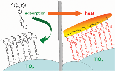
In this paper, we developed a simple yet effective method to reduce the electron recombination in DSSCs by functionalizing organic dyes with a thermally cross-linkable styryl group (Scheme 1, Fig. 1), which can be conveniently polymerized into polystyrene during the annealing step of the device fabrication. The thus formed polystyrene surrounding the absorbed dye layer on TiO2 serves as an electrolyte-blocking shell, impeding electron recombination and leading to enhanced efficiency of the resulting DSSC (Fig. 2). Using this strategy, a DSSC with > 30% improvement on the energy-conversion efficiency had been achieved. Furthermore, when incorporating another cross-linkable additive together with the styryl-functionalized dye for thermal polymerization, an overall 46.8% efficiency enhancement over the basic model device was accomplished. Our approach provides a new strategy for future development of functionalized organic dyes for efficient DSSCs.
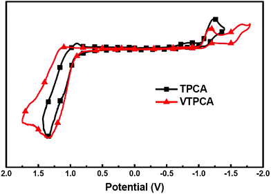 |
| | Fig. 2 Cyclic voltammetry of TPCA and VTPCA. The potentials were measured in the THF solution with 0.1 M TBAPF6 as the supporting electrolyte at a scan rate of 20 mV s−1. Fc/Fc+ was used as the internal standard. | |
 |
| | Scheme 1 Synthesis of VTPCA. | |
Results and discussion
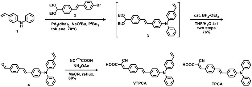
The dye TPCA (Scheme 1), first developed by Park and Kim in 2007,8a utilized stilbene as a π-bridge of the electron-donating diphenylamino group and the electron-withdrawing 2-cyanoacrylic acid, in which the carboxylic acid serves as the essential anchoring group toward the nanoporous TiO2 surface. We selected TPCA as the model core structure for further functionlization due to its good efficiency in DSSC and structural simplicity. Based on that, a vinylene group was introduced onto the electron-donating terminus of model TPCA, giving a thermally cross-linkable 4-vinylphenyl (styryl) group that was known to undergo efficient polymerization upon the thermal treatment.9 The synthetic routes of dye VTPCA equipped with a thermally cross-linkable styryl group are depicted in Scheme 1. The readily available molecules N-phenyl-4-vinylaniline 1 and (E)-1-bromo-4-(4-(diethoxymethyl)styryl)benzene 2 were coupled smoothly using Buchwald–Hartwig coupling conditions to give an acetal intermediate 3. Compound 3 was subjected to Lewis acid catalyzed hydrolysis to afford the aldehyde 4 in high yields. The Knoevenagel condensation of aldehyde 4 with 2-cyanoacetic acid in acetonitrile afforded the target molecule VTPCA in a 60% yield.
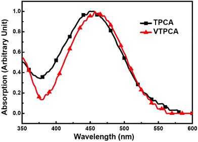
The electrochemical properties of cross-linkable dye VTPCA and model dye TPCA were investigated with cyclic voltammetry (CV, Fig. 2). These two dyes show similar irreversible redox behavior with the same oxidation onset potential located at 0.95 V (vs. Ag+/AgCl). As referred to the redox couple of ferrocene/ferrocenium (Fc/Fc+), the highest occupied molecular orbital (HOMO) energies of VTPCA and TPCA are estimated to be −5.18 eV (Table 1). Obviously, the incorporation of a vinylene group does not alter the electrochemical property of the parent compound TPCA (Fig. 2). Due to intramolecular charge transfer,8 the electronic absorption spectrum of VTPCA (with a maximum centered at 459 nm and the molar extinction coefficient ε459 = 2.13 × 10⁴ M−1 cm−1, Fig. 3 and Table 1) is slightly red-shifted as compared to that of TPCA (with an absorption maximum around 453 nm, ε453 = 1.94 × 10⁴ M−1 cm−1, Fig. 3 and Table 1). Using the optical band gaps of VTPCA and TPCA (Table 1) deduced from the absorption onsets, LUMO energy levels of VTPCA and TPCA were calculated to be −2.91 eV and −2.90 eV, respectively (Table 1), which are consistent with the reduction waves observed in CV. HOMO and LUMO energy levels of both dyes are both thermodynamically suitable for electron injection to the TiO2 conduction band and dye regeneration.8a,8b
Table 1 Properties of TPCA and VTPCA
| Dye |
λ
abs
a/nm |
ε
a/104 M−1 cm−1 |
HOMOb/eV |
E
opt
g
c/eV |
LUMOd/eV |
|
In CH2Cl2.
The HOMO level was determined from the oxidation onset of CV by referring to energy levels of the redox couple of ferrocene.
The band gap was calculated from the absorption onset.
The LUMO level was deduced by subtracting band gap from the HOMO level.
|
| VTPCA |
459 |
2.13 |
−5.18 |
2.27 |
−2.91 |
| TPCA |
453 |
1.94 |
−5.18 |
2.28 |
−2.90 |
The thermal polymerization characteristics of dye VTPCA and morphological properties of the resulting polymer were probed by differential scanning calorimetry (DSC, Fig. 4). In the first DSC scan of pristine VTPCA, an endothermic peak arising around 100 °C was observed and assigned as the glass transition temperature of the monomer, ca. 146 °C, the concomitant exothermic maximum was also detected, representing the thermal polymerization region. The second DSC scan of the same sample indicated no evident phase transition up to 200 °C, confirming the formation of a polymer upon thermal treatment of VTPCA. The polymerization of VTPCA takes place at a convenient temperature range that is compatible with the DSSC fabrication. Thermal polymerization of VTPCA adsorbed on nanoporous TiO2 was further characterized with FT-IR spectroscopy (Fig. 5).
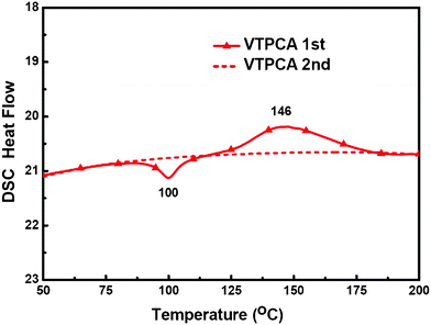 |
| | Fig. 4 The DSC curves of VTPCA. | |
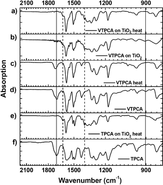 |
| | Fig. 5 The FT-IR spectra of VTPCA and TPCA. (a) VTPCA adsorbed on TiO2, after thermal treatment. Signals of vinyl group (∼900 cm−1) and carboxylic acid (∼1700 cm−1) disappeared. (b) VTPCA adsorbed on TiO2. (c) VTPCA after thermal treatment. (d) Pristine VTPCA film. (e) TPCA adsorbed on TiO2, after thermal treatment. (f) Pristine TPCA film. | |
The IR absorption band for the bending mode of the VTPCA vinyl group at 902 cm−1 disappeared after thermally annealling both for pristine VTPCA and for VTCPA adsorbed on TiO2, clearly indicating a high degree of polymerization. In addition, the strong absorption band of the free carboxylic acid (1697 cm−1) also disappeared when VTPCA was loaded onto the TiO2 surface, and two absorption band at 1619 cm−1 and 1391 cm−1 appeared simultaneously, which can be identified as asymmetric and symmetric stretching of carboxylate adsorbed on TiO2.10 Moreover, the frequency difference was calculated as 228 cm−1, which is consistent with ref. 8b, indicating a bidentate bridging behavior of the carboxylate. This result suggests that the new vinylene-functionalized dye VTPCA did anchor onto the TiO2 surface via carboxylic acid, and that upon thermal treatment, VTPCA efficiently formed a polymerized mono-layer rather than irregular polymeric clusters on the electrode surface.11TPCA and cross-linked VTPCA were then used as sensitizers for DSSCs to investigate their influence on photovoltaic characteristics (details of the device preparation and characterization are described in the experimental section). The photocurrent–voltage (J–V) characteristics (under the standard global AM 1.5G solar irradiation) of the DSSCs prepared from 0.5 mM dye solutions in acetonitrile (ACN) are shown in Fig. 6a. The TPCA cell (device 1) and the cross-linked VTPCA cell (device 2) show short-circuit photocurrent density (Jsc), open-circuit voltage (Voc), fill factor (FF), and power conversion efficiency (η) of (9.54 mA cm−2, 0.64 V, 0.64, 3.91%) and (9.01 mA cm−2, 0.71 V, 0.69, 4.41%), respectively (Table 2). Although the cross-linked VTPCA cell shows lower Jsc than the TPCA cell, yet its higher Voc and FF render it a 12.8% higher conversion efficiency (vs. the TPCA cell, Table 2). The higher Voc and FF of the cross-linked VTPCA cell may be ascribed to the effective suppression of charge recombination at the TiO2/dye/electrolyte interface.3–7 On the other hand, the lower Jsc of the cross-linked VTPCA cell may be attributed to the dye aggregation associated with shortening of inter-chromophore distances during cross-linking/polymerization. Dye aggregates had been known to cause the undesirable intermolecular interactions that lead to self-quenching and reduction of electron injection into TiO2.3,6–7,12 In order to mitigate such issue and to improve the efficiency, chenodeoxycholic acid (CDCA, 0.5 mM) was introduced as the co-adsorbent in chlorobenzene (CB) solutions of both dyes (0.5 mM) during the dye-adsorption step.12 With co-adsorption of CDCA, the TPCA-based cell (device 3) showed a slight augmentation in Voc and FF (vs. device 1), as can be seen in Fig. 6a and Table 2. Voc increased mainly because the CDCA uplifts the energy level of TiO2 conduction band.12a However, Jsc of the same device (device 3) decreased to 8.44 mA cm−2 since CDCA would compete for active sites and exclude those weakly anchored dye molecules, consequentially lowering the dye uptake on the TiO2 surface. As in device 3, with the presence of CDCA, Voc and FF of the cross-linked VTPCA cell (device 4) further increase as compared to device 2 (cross-linked VTPCA cell without CDCA), and remain higher than those of device 3 (Fig. 6a and Table 2). Yet in sharp contrast with device 3, the Jsc of device 4 (9.83 mA cm−2) does not decrease but increases instead (in comparison with device 2). These results clearly denote that the reduced dye uptakes (and photocurrent loss) induced by co-adsorbed CDCA is well compensated by suppression of charge recombination (and dark current) and inter-chromophore aggregation due to the presence of the electrolyte-blocking shell and CDCA, respectively. The simultaneous increments in Voc, Jsc, and FF of VTPCA-based device 4 have led to a significantly enhanced conversion efficiency of 5.31%, representing a 31.4% enhancement over TPCA-based device 3.
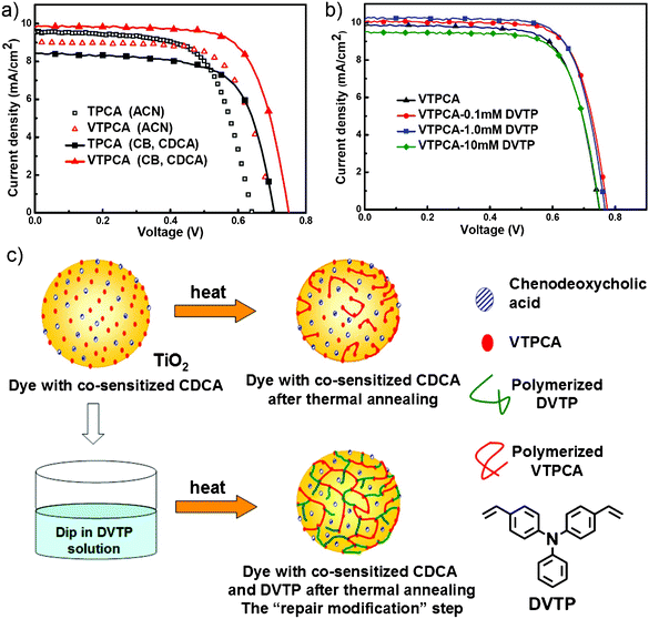 |
| | Fig. 6 (a) The J–V curves of TPCA and cross-linked VTPCA DSSCs prepared by soaking in different dye bath conditions. (b) The J–V curves of DSSCs subjected to the extra “repair modification” using the repair additive DVTP solutions of various concentrations. (c) The illustration of “repair modification” strategy. DVTP was used as the cross-linker. | |
Table 2 The device characteristics of DSSCs employing TPCA, cross-linked VTPCA and cross-linked VTPCA+DVTP under different conditions
| Device |
Dye, conditions |
Voc/V |
Jsc/mA cm−2 |
FF |
η/% |
Improved η/% |
|
Compared to device 1.
Compared to device 3.
Compared to device 4.
|
| 1 |
TPCA (ACN) |
0.64 |
9.54 |
0.64 |
3.91 |
— |
| 2 |
VTPCA (ACN) |
0.71 |
9.01 |
0.69 |
4.41 |
12.8a |
| 3 |
TPCA (CB, CDCA) |
0.70 |
8.44 |
0.68 |
4.04 |
3.3a |
| 4 |
VTPCA (CB, CDCA) |
0.74 |
9.83 |
0.73 |
5.31 |
31.4b |
| 5 |
VTPCA (CB, CDCA)/0.1 mM DVTP |
0.77 |
10.04 |
0.74 |
5.72 |
7.7c |
| 6 |
VTPCA (CB, CDCA)/1.0 mM DVTP |
0.76 |
10.20 |
0.74 |
5.74 |
8.1c 46.8a |
| 7 |
VTPCA (CB, CDCA)/10 mM DVTP |
0.75 |
9.50 |
0.73 |
5.20 |
−2.1c |
Although incorporation of CDCA is effective to improve cell efficiencies, inevitably it would reduce the dye uptake and increase intermolecular distances between adsorbed dyes. The latter in our present case would result in a lower degree of polymerization and thus a loose polymeric shell network. Therefore, we established a “repair modification” strategy, as illustrated in Fig. 6c, to strengthen the dye-protecting shell. In this case, after the dye/CDCA adsorption step, 4,4′-divinyltriphenylamine (DVTP) was introduced as a repair additive to fill the intermolecular spaces between TiO2-supported VTPCA molecules. The two styryl groups of DVTP together with styryl group of VTPCA provide a higher density of polymerizable sites, aiming to produce a more robust electrolyte-blocking shell after thermal annealing. The introduction of DVTP was accomplished by dipping the VTPCA/CDCA-loaded TiO2 films into solutions having different concentrations of DVTP (0.1, 1, and 10 mM in cyclohexane), followed by annealing at 150 °C for 20 min for thermal polymerization. The J–V characteristics of the cross-linked VTPCA+DVTP cells subjected to treatments in DVTP solutions of varied concentrations are shown in Fig. 6b, and the corresponding photovoltaic characteristics are summarized in Table 2. When treated in 0.1 and 1 mM DVTP solutions, the cross-linked VTPCA+DVTP cells (device 5 and device 6, respectively) show further enhanced Voc, Jsc, and FF in comparison with those of device 4, rendering an additional 7.7–8.1% enhancement in the conversion efficiencies (5.72% for device 5 and 5.74% for device 6). On the other hand, the treatment with the DVTP solution of even higher concentrations (e.g. 10 mM for device 7) does not bring further benefits, probably because overdosed DVTP would produce a thicker shell that would spatially jeopardize regular interactions between electrolytes and oxidized photosensitizers and retard the regeneration of photosensitizers. In summary, with properly controlling doping concentrations of the cross-linkable additive (DVTP), the “repair modification” has further enhanced the conversion efficiency of DSSCs using cross-linkable dyes. The effects of using the cross-linked dye on photovoltaic characteristics were further elucidated by electrochemical impedance spectroscopy (EIS), a useful tool for characterizing interfacial charge-transfer processes in DSSCs.13 In this study, EIS was carried out by subjecting the cell to the constant AM 1.5G illumination and to the bias at Voc of the cell (i.e., under the condition of no dc current),13a–13c for better manifesting the process at the TiO2/dye/electrolyte interface. Fig. 7a and 7b show the EIS Nyquist plots (i.e. minus imaginary part of the impedance-Z′′ vs. the real part of the impedance Z′ in sweeping the frequency) and the EIS Bode plots (i.e., the phase of the impedance vs. the frequency) for device 3 (TPCA), device 4 (cross-linked VTPCA), and device 5 (cross-linked VTPCA+DVTP). For the frequency range and bias conditions investigated (20 Hz to 1 MHz), in the Nyquist plots of Fig. 7a, the larger semicircle in the lower frequency range (∼20 Hz to 1 kHz) corresponds to the charge transfer processes at the TiO2/dye/electrolyte interface, while the smaller semicircle at higher frequencies corresponds to the charge transfer processes at the Pt/electrolyte interface.13c The larger width of the lower-frequency semicircle of the cross-linked VTPCA cell indicates a larger charge-transfer resistance (compared to the TPCA cell) at the TiO2/dye/electrolyte interface. The charge-transfer resistance is further enhanced with adding DVTP. In Bode plots of Fig. 7b, the characteristic frequency of the lower-frequency peak in the Bode plot is related to the charge recombination rate at the TiO2/dye/electrolyte interface and its reciprocal is associated with the electron lifetime.13d As can be seen in Fig. 7b, the lower-frequency peak of the cross-linked VTPCA cell shifts to a lower frequency (compared to the TPCA cell), indicating that the electron lifetime was effectively prolonged. The shift is further enlarged with adding DVTP. In general, the higher Voc value resulted from the higher conduction band edge and often contributes to a faster charge recombination rate at the same time because of the thermodynamic nature. However, the electron lifetime of devices measured under different Voc conditions (Fig. S2, ESI†) suggests that both of the devices using cross-linked dyes have earned higher lifetimes than that of reference TPCA device, indicating the charge recombination rate should be in the following order as TPCA > cross-linked VTPCA > cross-linked VTPCA+DVTP. The surface passivation evidently retards the electron recombination at the TiO2/dye/electrolyte interface and eventually overcomes the thermodynamic nature as a result. EIS results of Fig. 7a, 7b and Fig. S2 (ESI†) clearly suggest that the electrolyte-blocking shell formed through thermal polymerization effectively block ions in the electrolyte from approaching the TiO2 surface, suppressing charge recombination and lengthening electron lifetimes.7c Adding the cross-linker DVTP strengthens the blocking shell and enhances these effects. These factors in turn contribute to the higher Voc, Jsc, FF and IPCE (incident photon to current conversion efficiency, ESI†) of the cross-linked VTPCA and VTPCA+DVTP cells.14
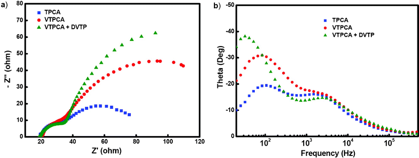 |
| | Fig. 7 (a) EIS Nyquist plots, and (b) EIS Bode plots of DSSCs using TPCA, cross-linked VTPCA, and cross-linked VTPCA+DVTP. | |
Conclusions
In summary, a simple and inventive strategy to suppress the undesirable electron recombination in DSSCs was devised and demonstrated by using the thermally cross-linkable organic dye sensitizer VTPCA. The polymerized dyes on the TiO2 electrode generate an electrolyte-blocking shell for effectively suppressing the electron recombination with the electrolyte, leading to efficiency enhancement. By introducing the co-adsorbent CDCA, the possible polymerization-caused dye aggregation was reduced, giving further efficiency enhancement. The “repair modification” strategy using the cross-linkable molecule DVTP as the repair additive was further invented to strengthen the polymeric network loosened by the co-adsorbent. The copolymerization of TiO2-bonded VTPCA and DVTP produces a robust shell for efficient electrolyte-blocking. All these strategies together give a 46.8% enhancement in the conversion efficiency in comparison with the basic model device (device 1). We believe the “electrolye-blocking shell” plus “repair modification” strategies reported in this work will trigger the advance of architectures and functionalized dyes for future efficient dye-sensitized solar cells.
Acknowledgements
We thank the financial support from the National Science Council of Taiwan (NSC 99-2221-E-002-118-MY3, 98-2119-M-002-007-MY3).
References
-
(a) M. Grätzel, J. Photochem. Photobiol., A, 2004, 164, 3 CrossRef;
(b) M. Grätzel, Progr. Photovolt.: Res. Appl., 2006, 14, 429 CrossRef;
(c) Y. Chiba, Y. Islam, Y. Watanabe, R. Komiya, N. Koide and L. Han, Jpn. J. Appl. Phys., 2006, 45, 24 CrossRef;
(d) C.-Y. Chen, M. Wang, J.-Y. Li, N. Pootrakulchote, L. Alibabaei, C. Ngoc-le, J-D. Decoppet, J.-H. Tsai, C. Grätzel, C.-G. Wu, S. M. Zakeeruddin and M. Grätzel, ACS Nano, 2009, 3, 3103 CrossRef CAS;
(e) Y. Cao, Y. Bai, Q. Yu, Y. Cheng, S. Liu, D. Shi, F. Gao and P. Wang, J. Phys. Chem. C, 2009, 113, 6290 CrossRef CAS;
(f) C.-C. Chou, K.-L. Wu, Y. Chi, W.-P. Hu, S. J. Yu, G.-H. Lee, C.-L. Lin and P.-T. Chou, Angew. Chem., Int. Ed., 2011, 50, 2054 CrossRef CAS;
(g) W.-C. Chang, H.-S. Chen, T.-Y. Li, N.-M. Hsu, Y. S. Tingare, C.-Y. Li, Y.-C. Liu, C. Su and W.-R. Li, Angew. Chem., Int. Ed., 2010, 49, 8161 CrossRef CAS.
-
(a) A. Mishra, M. K. R. Fischer and P. Bäuerle, Angew. Chem., Int. Ed., 2009, 48, 2474 CrossRef CAS;
(b) H. Imahori, T. Umeyama and S. Ito, Acc. Chem. Res., 2009, 42, 1809 CrossRef CAS;
(c) Y. Ooyama and Y. Harima, Eur. J. Org. Chem., 2009, 2903 CrossRef CAS;
(d) T. Bessho, S. M. Zakeeruddin, C.-Y. Yeh, E. W.-G. Diau and M. Grätzel, Angew. Chem., Int. Ed., 2010, 49, 6646 CrossRef CAS;
(e) W. Zeng, Y. Cao, Y. Bai, Y. Wang, Y. Shi, M. Zhang, F. Wang, C. Pan and P. Wang, Chem. Mater., 2010, 22, 1915 CrossRef CAS;
(f) H. Choi, I. Raabe, D. Kim, F. Teocoli, C. Kim, K. Song, J.-H. Yum, J. Ko, M. K. Nazeeruddin and M. Grätzel, Chem.–Eur. J., 2010, 16, 1193 CrossRef CAS;
(g) S. Ito, H. Miura, S. Uchida, M. Takata, K. Sumioka, P. Liska, P. Comte, P. Péchyb and M. Grätzel, Chem. Commun., 2008, 5194 RSC;
(h) N. Cho, H. Choi, D. Kim, K. Song, M.-s. Kang, S. O. Kang and J. Ko, Tetrahedron, 2009, 65, 6236 CrossRef CAS;
(i) L.-Y. Lin, C.-H. Tsai, K.-T. Wong, T.-W. Huang, C.-C. Wu, S.-H. Chou, F. Lin, S.-H. Chen and A.-I. Tsai, J. Mater. Chem., 2011, 21, 5950 RSC.
- S. E. Koops, P. R. F. Barnes, B. C. O'Regan and J. R. Durrant, J. Phys. Chem. C, 2010, 114, 8054 CAS.
-
(a) E. Palomares, J. N. Clifford, S. A. Haque, T. Lutz and J. R. Durrant, Chem. Commun., 2002, 1464 RSC;
(b) R. Gao, L. Wang, B. Ma, C. Zhan and Y. Qiu, Langmuir, 2010, 26, 2460 CrossRef CAS.
- S. A. Haque, S. Handa, K. Peter, E. Palomares, M. Thelakkat and J. R. Durrant, Angew. Chem., Int. Ed., 2005, 44, 5740 CrossRef CAS.
-
(a) Z. Ning, Q. Zhang, H. Pei, J. Luan, C. Lu, Y. Cui and H. Tian, J. Phys. Chem. C, 2009, 113, 10307 CrossRef CAS;
(b) S.-H. Lin, Y.-C. Hsu, J. T. Lin, C.-K. Lin and J.-S. Yang, J. Org. Chem., 2010, 75, 7877 CrossRef CAS.
-
(a) N. Koumura, Z.-S. Wang, S. Mori, M. Miyashita, E. Suzuki and K. Hara, J. Am. Chem. Soc., 2006, 128, 14256 CrossRef CAS;
(b) J. E. Kroeze, N. Hirata, S. Koops, M. K. Nazeeruddin, L. Schmidt-Mende, M. Grätzel and J. R. Durrant, J. Am. Chem. Soc., 2006, 128, 16376 CrossRef CAS;
(c) S. Kim, D. Kim, H. Choi, M.-S. Kang, K. Song, S. O. Kang and J. Ko, Chem. Commun., 2008, 4951 RSC.
-
(a) S. Hwang, J. H. Lee, C. Park, H. Lee, C. Kim, C. Park, M.-H. Lee, W. Lee, J. Park, K. Kim, N.-G. Park and C. Kim, Chem. Commun., 2007, 4887 RSC;
(b) H. Tian, X. Yang, R. Chen, R. Zhang, A. Hagfeldt and L. Sun, J. Phys. Chem. C, 2008, 112, 11023 CrossRef CAS;
(c) M. Ziółek, X. Yang, L. Sun and A. Douhal, Phys. Chem. Chem. Phys., 2010, 12, 8098 RSC.
-
(a) C.-Y. Lin, Y.-C. Lin, W.-Y. Hung, K.-T. Wong, R. C. Kwong, S. C. Xia, Y.-H. Chend and C.-I. Wu, J. Mater. Chem., 2009, 19, 3618 RSC;
(b) N. B. McKeown, S. Badriyab, M. Helliwellb and M. Shkunovc, J. Mater. Chem., 2007, 17, 2088 RSC;
(c) N. Haberkorn, J. S. Gutmann and P. Theato, ACS Nano, 2009, 3, 1415 CrossRef CAS.
-
(a) K. S. Finnie, J. R. Bartlett and J. L. Woolfrey, Langmuir, 1998, 14, 2744 CrossRef CAS;
(b) R. Argazzi and C. A. Bignozzi, Inorg. Chem., 1994, 33, 5741 CrossRef CAS;
(c)
E. Pretsch, T. Clerc, J. Siebl and W. Simon, in Tables of Spectral Data for Structure Determination of Organic Compounds, 2nd Edition, I25–I45, Springer-Verlag, Berlin, 1989 Search PubMed.
-
(a) W. Gao, L. Dickinson, C. Grozinger, F. G. Morin and L. Reven, Langmuir, 1996, 12, 6429 CrossRef CAS;
(b) S. K. Hau, H.-L. Yip, O. Acton, N. S. Baek, H. Ma and K.-Y. Jen Alex, J. Mater. Chem., 2008, 18, 5113 RSC.
-
(a) N. R. Neale, N. Kopidakis, J. van de Lagemaat, M. Grätzel and A. J. Frank, J. Phys. Chem. B, 2005, 109, 23183 CrossRef CAS;
(b) M. Pastore and F. De Angelis, ACS Nano, 2010, 4, 556 CrossRef CAS;
(c) A. Kay and M. Grätzel, J. Phys. Chem., 1993, 97, 6272 CrossRef CAS;
(d) H. Choi, S. O. Kang, J. Ko, G. Gao, H. S. Kang, M.-S. Kang, Md. K. Nazeeruddin and M. Grätzel, Angew. Chem., Int. Ed., 2009, 48, 5938 CrossRef CAS.
-
(a) Q. Wang, J.-E. Moser and M. Grätzel, J. Phys. Chem. B, 2005, 109, 14945 CrossRef CAS;
(b) Z. Zhang, S. M. Zakeeruddin, B. C. O'Regan, R. Humphry-Baker and M. Grätzel, J. Phys. Chem. B, 2005, 109, 21818 CrossRef CAS;
(c) L.-Y. Lin, C.-H. Tsai, K.-T. Wong, T.-W. Huang, L. Hsieh, S.-H. Liu, H.-W. Lin, C.-C. Wu, S.-H. Chou, S.-H. Chen and A.-I. Tsai, J. Org. Chem., 2010, 75, 4778 CrossRef CAS;
(d) M. Adachi, M. Sakamoto, J. Jiu, Y. Ogata and S. Isoda, J. Phys. Chem. B, 2006, 110, 13872 CrossRef CAS;
(e) J. Bisquert, F. Fabregat-Santiago, I. Mora-Seró, G. Garcia-Belmonte and S. Giménez, J. Phys. Chem. C, 2009, 113, 17278 CrossRef CAS;
(f) F. Fabregat-Santiago, G. Garcia-Belmonte, I. Mora-Seró and J. Bisquert, Phys. Chem. Chem. Phys., 2011, 13, 9083 RSC.
-
(a) H.-W. Lin, S.-Y. Ku, H.-C. Su, C.-W. Huang, Y.-T. Lin, K.-T. Wong and C.-C. Wu, Adv. Mater., 2005, 17, 2489 CrossRef CAS;
(b) C.-J. Yang, T.-Y. Cho, C.-L. Lin and C.-C. Wu, Appl. Phys. Lett., 2007, 90, 173507 CrossRef;
(c) C.-Y. Yang, T.-Y. Cho, Y.-Y. Chen, C.-J. Yang, C.-Y. Meng, C.-H. Yang, P.-C. Yang, C.-C. Wu and S.-C. Lee, Appl. Phys. Lett., 2007, 90, 233512 CrossRef;
(d) C.-J. Yang, T.-Y. Cho, C.-L. Lin and C.-C. Wu, J. Soc. Inf. Disp., 2008, 16, 691 CrossRef CAS.
Footnote |
| † Electronic Supplementary Information (ESI) available: experimental details of device fabrication, characteristics measurements, synthesis and characterization of new compounds, IPCE spectra, plot of electron lifetime. See DOI: 10.1039/c2ra01272c/ |
|
| This journal is © The Royal Society of Chemistry 2012 |
Click here to see how this site uses Cookies. View our privacy policy here.