Synthesis of rigid and stable large-inner-diameter multiwalled carbon nanotubes†
Yulin
Huang
,
Dionisios G.
Vlachos
* and
Jingguang G.
Chen
*
Catalysis Center for Energy Innovation, Center for Catalytic Science and Technology, Department of Chemical Engineering, University of Delaware, Newark, DE 19716-3111, USA. E-mail: jgchen@udel.edu (J.G.C.); vlachos@udel.edu (D.G.V.)
First published on 25th January 2012
Abstract
Rigid large-inner-diameter (> 15.0 nm) multiwalled carbon nanotubes (LID-MWCNTs) were synthesized from cetyltrimethylammonium bromide (CTAB) and ammonium metatungstate, in which CTAB was converted to CNT structure and ammonium metatungstate was converted to WC nanoparticles inside of LID-MWCNTs.
Since the first synthesis of carbon nanotubes (CNTs) by Iijima in 1991,1 significant enthusiasm and interest in different nanostructured CNTs have sustained in the scientific community because of their unique chemical and physical properties, such as extremely high tensile strengths, high elastic moduli, low density, good chemical and environmental stabilities, and high thermal and electrical conductivities.2,3 In the last two decades CNTs have been applied in polymer reinforcement and conductive plastics for the automotive and energy industry.4–6 Furthermore, CNTs are promising nanomaterial candidates for medicine,7 electronics,8–10 energy production and storage,6,11 catalysis12–16 and catalyst supports.17–20 Among all the CNTs, one of the least studied are large diameter CNTs (d > 4 nm),21–23 which possibly become less stable and are expected to collapse when CNTs become larger.24,25 With appreciable control of the diameter and the number of walls in the CNTs, rigid large-diameter MWCNTs have been reported.21 However, the inner diameter of the reported CNTs is still difficult to control efficiently, although the inner space of CNTs is very important for advanced catalysis,17 nanoreactors16,17 and energy conversion/storage.14,15 Furthermore, the inner diameters of the reported CNTs are mostly less than a few nanometres,3 which limits the fluid transport inside of the tube due to diffusion limitation.
In the current study we demonstrate the synthesis of rigid large-inner-diameter multiwalled carbon nanotubes (LID-MWCNTs) from a cationic surfactant, cetyltrimethylammonium bromide (CTAB), and ammonium metatungstate by directly thermal annealing.26 The rigid LID-MWCNTs were produced by the formation of tungsten carbide nanoparticles inside the tube, which is different from the conventional formation of CNTs by arc discharge,1 laser ablation27 and chemical vapour deposition (CVD).20 The formed WC nanoparticles could either be removed and regenerated to be reused for LID-MWCNTs synthesis or be used for CNT-confined catalysts. Characterization results confirmed that LID-MWCNTs started from the formation of the WO3 nanowires with the in situ polymerization of surfactant on the WO3 nanowire surface, which was followed by the carbonization of the polymer layer into pure CNT and the carburization of the WO3 nanowire to the WC nanoparticles. After the chemical removal of the WC nanoparticles from the LID-MWCNTs, pure and rigid LID-MWCNTs were obtained and confirmed.
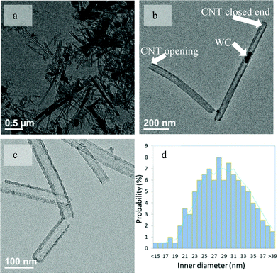
A representative transmission electron microscopy (TEM) image of LID-MWCNTs prepared from CTAB and ammonium metatungstate is shown in Fig. 1a. It can be seen that the LID-MWCNTs are rather straight and there is almost no amorphous carbon or carbon particles attached to the smooth surface of the tube. Both the closing and opening end are observed for LID-MWCNTs (Fig. 1b) with a uniform wall thickness (∼10.0 nm). The outer diameter of LID-MWCNT was measured by TEM, and the distribution of the outer diameters of 200 LID-MWCNTs was mainly centered in the range of 30.0–55.0 nm, as shown in Fig. S1, ESI.† A mean outer diameter of 42.0 nm was obtained in the range of typical large-outer-diameter MWCNTs between 2.0–100.0 nm.16,25 The uniform tubular structure of the LID-MWCNT was also confirmed by scanning electron microscopy (SEM) images, as shown in Fig. S2, ESI.†
 | ||
| Fig. 1 Representative TEM images of LID-MWCNTs prepared from CTAB and ammonium metatungstate before the WC removal (a, b) and after the removal of WC (c). The inner diameter distribution of LID-MWCNTs (d). | ||
Most importantly, the inner diameters of LID-MWCNTs are typically larger than 15 nm (Fig. 1d). The larger inner diameter could be related to the size of the final WC nanoparticles inside of the tube as confirmed by XRD in Fig. S3, ESI† and high resolution TEM in Fig. S4†. The formation of LID-MWCNTs was reasonable when there were WC nanoparticles inside of the tubes. Surprisingly, after the WC was removed by chemical etching with H2O2 and sulfuric acid followed by washing with NaOH aqueous solution, the tubular structure of these LID-MWCNTs was still stable, as shown in Fig. 1c and Figure S5, ESI.† Such observation suggests that the rigid structure of LID-MWCNTs is not stabilized solely by WC nanoparticles. It is likely that the thickness of the CNT wall (10.0 nm) is large enough to stabilize the rigid structure of LID-MWCNTs. LID-MWCNT has good Raman scattering characteristics (Fig. S6, ESI†) although the intensity ratio of the D band (∼1330 cm−1) to G band (∼1590 cm−1) is 1.4. This result indicates that the graphitization of this LID-MWCNT is not completed under the current synthesis conditions.
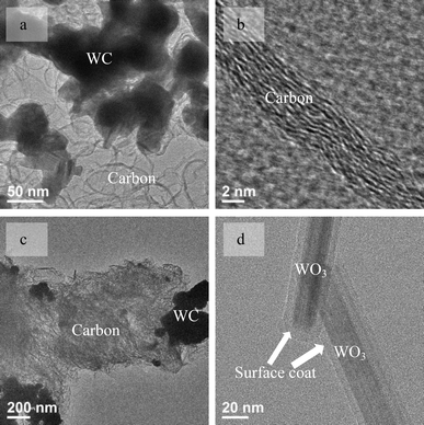
The WC nanoparticles inside the tube could be considered as the seeds and catalysts to grow LID-MWCNTs in the way of traditional CNT catalysts, such as Fe, Co, Ni nanoparticles and single crystals.3 However, it was found that neither LID-MWCNT nor normal CNTs could be synthesized using WC nanoparticles as catalysts. As shown in Fig. 2a and 2b, multilayer graphitic structures with an inter-layer distance of ∼3.4 Å were produced around the WC nanoparticles without any tubular structure using the same carbon source, CTAB. Another catalyst candidate for the synthesis of LID-MWCNT was thought to be the WO3 nanoparticle, which was identified as the intermediate during the synthesis of WC from ammonium metatungstate. Again, neither LID-MWCNTs nor normal CNTs could be synthesized from CTAB with WO3 nanoparticles (Fig. S7 and S8, ESI†) and only amorphous carbon was produced, as shown in Fig. 2c. Additionally, instead of CNTs, only amorphous carbon was produced on WC nanoparticles or WO3 nanoparticles from methane, one of the commonly used carbon sources for CNT synthesis. Results from both WC and WO3 nanoparticles indicated that the WC or WO3 nanoparticles could not catalyze the formation of any CNTs following conventional three-step vapour-liquid-solid (VLS) or vapour-solid-solid (VSS) growth mechanisms in catalytic chemical vapour deposition (CCVD).2
 | ||
| Fig. 2 TEM images of carbon/WC hybrid materials produced from CTAB/WC nanoparticles (a, b), CTAB/WO3 nanoparticles (c) and WO3 nanowires with a polymer coat on their surface (d). | ||
In order to investigate the growth mechanism for LID-MWCNTs, the effect of temperature on the growth of LID-MWCNTs was studied. When CTAB was mixed with ammonium metatungstate in solution, a white precipitate was observed due to the interaction between cation cetyltrimethylammonium (CTA+) and the anion metatungstate (H2W12O406−) (eqn (1)). However, as shown in Fig. S9, ESI,† a well-defined nanostructure was not produced.
| nCTAB(aq) + n(NH4)6H2W12O40(aq) = nNH4Br(aq) + [(CTA)6H2W12O40]n(s) | (1) |
WO3 was formed due to the thermal decomposition of ammonium metatungstate once the temperature reached approximately 573 K during the synthesis of LID-MWCNTs with a slow heating rate (0.5 K min−1). Because of the electrostatic attraction between CTA+ and metatungstate, WO3 nanowires could be formed, as shown in Fig. 2d and Fig. S10.† CTAB was polymerized and formed a coating around the WO3 nanowire surface during the formation of WO3 nanowires. The composition of the coating was confirmed by elemental analysis with the ratio of H/C at around 1.8, as listed in Table S1.† This value suggested that a partial carbonization of the coating on WO3 already happened due to its lower H/C ratio compared to the ratio of H/C in CTAB (2.2). With increased temperature, the H/C ratio in the material decreased continuously, as listed in Table S1.†
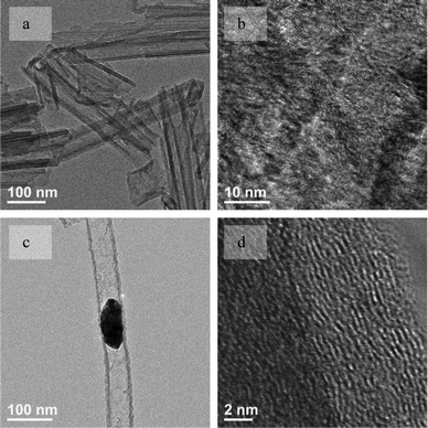
When the surface-coated WO3 nanowire was heated to over 973 K, carbonization of the coating was almost completed because hydrogen could no longer be detected. The WO3/C hybrid materials could be recognized as LID-MWCNTs filled with WO3 nanowires. Once the WO3 was removed completely from the LID-CNT's tube with aqueous sodium hydroxide solution at room temperature overnight, most of the CNT structure was partially destroyed and collapsed, as shown in Fig. 3a. This observation was consistent with reported results about the collapse of large diameter CNTs due to their intrinsic instability.21,24 Additionally, as shown in Fig. 3b, the HRTEM image of collapsed LID-MWCNT's wall shows amorphous carbon without any ordered structure, which might contribute to the instability of the tube structure of LID-MWCNT.
 | ||
| Fig. 3 TEM images of collapsed LID-MWCNTs (a) and their amorphous carbon wall (b) after the removal of WO3 nanoparticles. TEM images of the rigid LID-MWCNT (c) and the ordered carbon wall (d) before the removal of WC nanoparticles. | ||
By increasing the reaction temperature to 1273 K, WO3 inside the LID-MWCNTs was converted to WC nanoparticles, as shown in Fig. 3c, which was confirmed by XRD and HRTEM in Fig. S3 and S4,† respectively. The wall of the LID-MWCNT was changed to a more ordered carbon structure with an inter-layer distance of ∼3.4 Å, as shown in Fig. 3d. These results suggests that the formed WC might catalyze the aromatization of amorphous carbon into a more ordered graphitic structure. The amorphous carbon in the LID-MWCNTs/WO3 nanowire composites acts as the carbon source for the carburization of WO3 to WC, which could also be confirmed by the formation of graphitic layers from the reaction between CTAB and the WC nanoparticles, as shown in Fig. 2a. With this more ordered carbon wall, LID-MWCNTs develop rigid and stable tubular structures that do not collapse after the partial (Fig. S5, ESI†) and complete (Fig. 1c) removal of the WC nanoparticles. It is clear that the WO3 nanowires and WC nanoparticles formed inside the LID-MWCNTs are key factors which physically prevent collapse during the formation of the tubular structure at lower temperatures and also strengthen the LID-MWCNT wall to a more ordered structure at higher temperatures.
In conclusion, rigid and stable large-inner-diameter carbon nanotubes have been synthesized successfully from cationic surfactant and ammonium metatungstate. The results indicate that the synergistic syntheses of WO3 nanowires and WC nanoparticles inside the tubes are very important to form and stabilize the large-inner-diameter carbon nanotubes' rigid tubular structure. After the removal of tungsten carbide nanoparticles from LID-MWCNTs, these rigid LID-MWCNTs could offer new opportunities for many CNT-based nanodevices. As described in previous studies, CNT confined precious metal catalysts often show unique catalytic properties.17,28 Due to the general catalytic similarities between WC and precious metals,29,30 WC nanoparticle confined in LID-MWCNTs can be potentially used as CNT-confined catalysts.
Acknowledgements
We gratefully acknowledge financial support from the U.S. Department of Energy, Office of Science, Office of Basic Energy Sciences under Award Number DE-SC0001004 for the Catalysis Center for Energy Innovation, an Energy Frontier Research Center. We also appreciate the suggestions on this manuscript from Dr Jean-Philippe Tessonnier at University of Delaware.References
- S. Iijima, Nature, 1991, 354, 56–58 CrossRef CAS.
- J.-P. Tessonnier and D. S. Su, ChemSusChem, 2011, 4, 824–847 CrossRef CAS.
- Q. Zhang, J.-Q. Huang, M.-Q. Zhao, W.-Z. Qian and F. Wei, ChemSusChem, 2011, 4, 864–889 CrossRef CAS.
- J. Markarian, Plast. Addit. Compd., 2005, 7, 18–21 CrossRef CAS.
- M. Baibarac and P. Gomez-Romero, J. Nanosci. Nanotechnol., 2006, 6, 289–302 CAS.
- J. Zhang, Y.-S. Hu, J.-P. Tessonnier, G. Weinberg, J. Maier, R. Schloegl and D. S. Su, Adv. Mater., 2008, 20, 1450–1455 CrossRef CAS.
- A. Bianco, K. Kostarelos and M. Prato, Chem. Commun., 2011, 47, 10182–10188 RSC.
- X. Wang, L. Zhang, Y. Lu, H. Dai, Y. K. Kato and E. Pop, Appl. Phys. Lett., 2008, 91, 261102/261101–261102/261103 Search PubMed.
- Z. Xu, W. Lu, W. Wang, C. Gu, K. Liu, X. Bai, E. Wang and H. Dai, Adv. Mater., 2008, 20, 3615–3619 CrossRef CAS.
- L. Zhang, S. Zaric, X. Tu, X. Wang, W. Zhao and H. Dai, J. Am. Chem. Soc., 2008, 130, 2686–2691 CrossRef CAS.
- Y.-J. Xu, X. Liu, G. Cui, B. Zhu, G. Weinberg, R. Schloegl, J. Maier and D. S. Su, ChemSusChem, 2010, 3, 343–349 CAS.
- J. Zhang, X. Liu, R. Blume, A. Zhang, R. Schloegl and D. S. Su, Science, 2008, 322, 73–77 CrossRef CAS.
- B. Frank, M. Morassutto, R. Schomaecker, R. Schloegl and D. S. Su, ChemCatChem, 2010, 2, 644–648 CrossRef CAS.
- D. S. Su and R. Schloegl, ChemSusChem, 2010, 3, 136–168 CrossRef CAS.
- D. S. Su, J. Zhang, B. Frank, A. Thomas, X. Wang, J. Paraknowitsch and R. Schloegl, ChemSusChem, 2010, 3, 169–180 CrossRef CAS.
- J.-P. Tessonnier, A. Villa, O. Majoulet, D. S. Su and R. Schlögl, Angew. Chem., Int. Ed., 2009, 48, 6543–6546 CrossRef CAS.
- X. Pan, Z. Fan, W. Chen, Y. Ding, H. Luo and X. Bao, Nat. Mater., 2007, 6, 507–511 CrossRef CAS.
- W. Zheng, J. Zhang, B. Zhu, R. Blume, Y. Zhang, K. Schlichte, R. Schloegl, F. Schueth and D. S. Su, ChemSusChem, 2010, 3, 226–230 CrossRef CAS.
- L. Shao, W. Zhang, M. Armbruester, D. Teschner, F. Girgsdies, B. Zhang, O. Timpe, M. Friedrich, R. Schloegl and D. S. Su, Angew. Chem., Int. Ed., 2011, 50, 10231–10235 CrossRef CAS.
- J. H. Bitter, J. Mater. Chem., 2010, 20, 7312–7321 RSC.
- N. T. Alvarez, F. Li, C. L. Pint, J. T. Mayo, E. Z. Fisher, J. M. Tour, V. L. Colvin and R. H. Hauge, Chem. Mater., 2011, 23, 3466–3475 CrossRef CAS.
- B. Yu, C. Liu, P.-X. Hou, Y. Tian, S. Li, B. Liu, F. Li, E. I. Kauppinen and H.-M. Cheng, J. Am. Chem. Soc., 2011, 133, 5232–5235 CrossRef CAS.
- D. N. Futaba, J. Goto, S. Yasuda, T. Yamada, M. Yumura and K. Hata, J. Am. Chem. Soc., 2009, 131, 15992–15993 CrossRef CAS.
- M. Motta, A. Moisala, I. A. Kinloch and A. H. Windle, Adv. Mater., 2007, 19, 3721–3726 CrossRef CAS.
- R. Wang, Y.-F. Hao, Z.-Q. Wang, H. Gong and J. T. L. Thong, Nano Lett., 2010, 10, 4844–4850 CrossRef CAS.
- J. Geng, D. Jefferson and B. F. G. Johnson, J. Mater. Chem., 2005, 15, 844–849 RSC.
- T. Guo, P. Nikolaev, A. G. Rinzler, D. TomBnek, D. T. Colbert and R. E. Smalley, J. Phys. Chem., 1995, 99, 10694–10697 CrossRef CAS.
- X. Pan and X. Bao, Acc. Chem. Res., 2011, 44, 553–562 CrossRef CAS.
- D. V. Esposito and J. G. Chen, Energy Environ. Sci., 2011, 4, 3900–3912 CAS.
- R. B. Levy and M. Boudart, Science, 1973, 181, 547–549 CAS.
Footnote |
| † Electronic Supplementary Information (ESI) available: Materials synthesis and characterizations. See DOI: 10.1039/c2ra01334g/ |
| This journal is © The Royal Society of Chemistry 2012 |
