Facile synthesis of porous nickel manganite materials and their morphology effect on electrochemical properties†
Huan
Pang
*ab,
Jiawei
Deng
a,
Shaomei
Wang
a,
Sujuan
Li
*a,
Jimin
Du
a,
Jing
Chen
a and
Jiangshan
Zhang
a
aKey Laboratory for Clearer Energy and Functional Materials of Henan Province, College of Chemistry and Chemical Engineering, Anyang Normal University, Anyang, 455000, Henan, P.R. China
bState Key Laboratory of Coordination Chemistry, Nanjing University, P.R. China.. E-mail: huanpangchem@hotmail.com; lisujuan1981@gmail.com
First published on 1st May 2012
Abstract
New porous bipyramid, fusiform and plate structured NiMn2O4 materials have been successfully synthesized by calcining oxalate precursors in the air without using any template or surfactant. More importantly, electrochemical measurements show that morphology affects their electrochemical properties, and the porous plate structured NiMn2O4 showed a large specific capacitance and a long cycle life.
Nano-micro materials generally show many size and shape-dependent complicated physical and chemical properties which are interesting for device applications.1–15 With the development of nanoscience, nanoscale spinel oxides has been pursued extensively in the last few years.16–25 Nanoscale spinel oxides hold many physical-chemical properties because of their distinct cation distribution.26,27 Particularly, among the manganese spinels, nickel manganite (NiMn2O4) spinel-type oxides exhibit a partially inverse cubic spinel structure, which has been well known for many years.28–30 Recently, Yu et al. have reported that the crystal phase of mesoporous NiMn2Ox can be tuned (hematite or spinel) by simply changing the annealing temperature (600 or 800 °C).31
Recently, demand for the development of alternative energy storage-conversion devices with high power and energy densities has increased to a great extent.32 Electrochemical capacitors have gained enormous attention due to their higher power density and longer cycle life compared to secondary batteries, and higher energy density than conventional double electrical layer capacitors.33,34 In particular, hydrous ruthenium oxide-based materials exhibit outstanding specific capacitance and longer cycle life than conventional materials.33,35,36 However, the high cost of this noble metal material limits it from commercialization and the search for alternative inexpensive electrode materials is essential.
Herein, we have successfully synthesized porous structured NiMn2O4 by oxalate precursors calcined in the air. We did not use any template or surfactant, and chose an oxalate precursor (the decomposition of mixture of nickel manganese oxalates (NiMn2(C2O4)3·nH2O)) that has low cost, good structure stability, and relatively low decomposition temperature. More importantly, there are nearly no reports about electrochemical capacitors of porous structured NiMn2O4. We have successfully explored the application of porous structured NiMn2O4 as electrochemical capacitors. The study of electrochemical measurements shows that the structure affects their electrochemical properties. The porous plate structured NiMn2O4 materials have a large specific capacitance 180 F g−1. The cycle life study shows that porous plate structured NiMn2O4 electrode can maintain 92.8% after 1000 cycles. To understand the electrode kinetics, the activation energies of the as-prepared NiMn2O4 materials for ion intercalation were estimated by electro-chemical impedance spectra. And as well, it is a good example to prove that physical and chemical properties of porous structured materials are related to their nanostructures, and the precise control of morphology of nanomaterials will serve for control of performance.
From Scheme 1, we can see the synthesis process of precursors. Three precursors can be successfully synthesized by changing the concentration of the raw materials at room temperature without using any templates or surfactants (detailed experimental procedures can be seen in the ESI†).
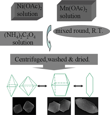 | ||
| Scheme 1 The synthesis process of precursors. | ||
From the EDS data of precursors (Table S1, ESI†), the precursors are formed from Ni, Mn, C, O and the content of three precursors is nearly the same. The powder X-ray diffraction patterns of precursors are shown in the ESI (Fig. S1a–c); all peaks are good in agreement with the corresponding standard cards, JCPDS 14-0742 & 02-0544 for NiC2O4·2H2O & MnC2O4·2H2O. The oxalates were calcined at 450 °C for 1 h to obtain porous structured NiMn2O4, and their XRD patterns are shown in Fig. 1a. All the peaks were indexed on NiMn2O4 (JCPDS 71-0852), which means the precursor has transformed into NiMn2O4 completely. The crystal structure of the NiMn2O4 unit cell is shown in Fig. 1b. It is simulated according to the crystallographic data in ref. 37 and the values given by the Inorganic Crystal Structure Database (ICSD 201398). In the spinel structure, Ni2+, Mn2+, Mn3+ and Mn4+ ions can coexist, and are distributed among the tetrahedral and octahedral spinel sites due to their pressure and temperature-dependent structural instability, which results in the related change of the electronic configuration of the Mn cations.38
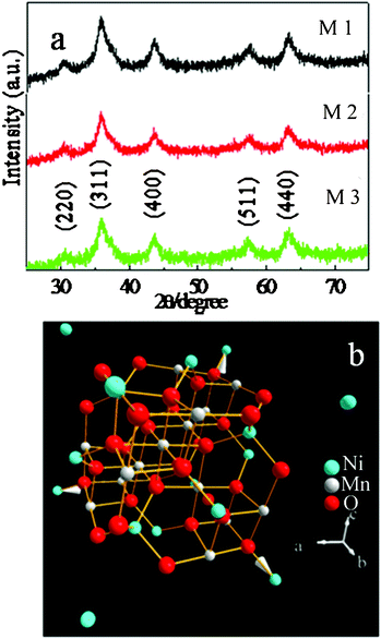 | ||
| Fig. 1 (a) XRD patterns of as-prepared NiMn2O4; M1: bipyramid, M2: fusiform, M3: plate; (b) the crystal structure of NiMn2O4 unit cell. | ||
The morphologies of precursors were observed by SEM. The precursor morphology is bipyramidal (Fig. 2a, b) and the size is about 4–5 μm. Unlike other bipyramids, one angle of the bipyramid precursor is 130° (marked by red arrows in Fig. 2b). The fusiform structure is shown in Fig. 2c, d. The size of structure is about 5–6 μm and one angle transforms into 100° (marked by red arrows in Fig. 2d). From Fig. 2e, f, the size of plate structured precursor is about 7–10 μm and one angle is also 100° the same as that of Fig. 2d (marked by red arrows in Fig. 2f).
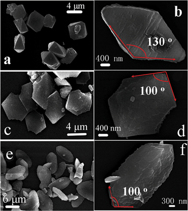 | ||
| Fig. 2 Scanning electron microscopy (SEM) images of as-prepared precursors (a, b: bipyramid; c, d: fusiform; e, f: plate). | ||
From TG curves of precursors (Fig. S2, ESI†), three precursors decomposed with increasing temperature in the air, and remained stable after 450 °C. In Fig. 3, we can see that all of the morphologies of precursors were maintained after calcinations in the air, but the surface of the structures have changed a bit with coarse areas. From the inset of Fig. 3a, named M1, there are some gaps (about 10–50 nm) on the surface of bipyramidal structures which might be caused by the released gases in the thermal conditions (seen ESI, Fig. 2†). And, as well, the corresponding EDS mappings of bipyramid NiMn2O4 were also tested (Fig. 3b1–3b3), and we can see three elements Ni, Mn and O retained completely. The fusiform structure was approximately maintained (Fig. 3c–d, named M2), and there are also several gaps on two ends of fusiform NiMn2O4. The plate NiMn2O4 (named M3) can be easily obtained by calcining the plate precursor. From a detailed observation in Fig. 3e–f, no pore or gap was seen on the plate structure. All the above data are in accord with the EDS data of NiMn2O4 in Table S1 (ESI†), which proves that NiMn2O4 materials were successfully synthesized.
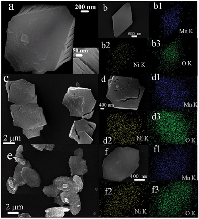 | ||
| Fig. 3 SEM images of as-prepared NiMn2O4, (a, b: M1; c, d: M2; e, f: M3); b1–b3, d1–d3, f1–f3: corresponding EDS mapping images. | ||
There might be some porous structures retained after gas release. And to more clearly and correctly describe porous properties of structured NiMn2O4 materials, TEM images of all samples were shown in Fig. 4. All the samples show the porous structure, and the pores are distributed homogeneously among the small primary particles (several nanometers) throughout the whole polyhedron structures (several micrometers). There are thousands of pores in a polyhedron structure for M1, M2 and M3. HRTEM results of porous nickel manganite materials have been shown in the insets of Fig. 4b, d, f, and we found that all samples have mostly preferred to expose the (222) crystal plane. This is important as such exposed facets may affect their electrochemical properties.
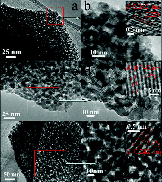 | ||
| Fig. 4 TEM images of NiMn2O4 materials; a, b: M1; c, d: M2; e, f: M3. | ||
To gain further insight into the porous structure and pore size distribution of the polyhedron structures, Brunauer-Emmett-Teller (BET) measurements were performed to examine their specific structural properties; the BET surface areas of M1, M2 and M3 are 127.0, 118.3 and 115.1 m2 g−1, respectively, which give efficient contact of the electrolyte with porous polyhedron structures. The histogram of pore size distribution data calculated using adsorption curves is presented in Fig. 5; the pore size is uniform, within the range of the mesopores (5–10 nm). These porous structures do not only offer as high surface areas, but provide good electrolyte access.
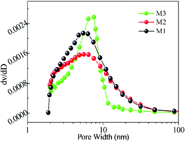 | ||
| Fig. 5 Histogram of the pore size distribution (PSD) data for M1–M3. | ||
Recently some ferrite oxides have been reported to exhibit pseudocapacitance.39 Therefore we have tried to explore the electrochemical properties of porous structured NiMn2O4 by cyclic voltammetry (CV) and chronopotentiometry (CP). Fig. 6a shows CV curves of structured NiMn2O4 materials at 5 mV s−1. The shapes are different from that of electric double layer capacitance, which normally shows an approximately rectangular shape, suggesting that the capacity mainly results from pseudocapacitive capacitance. Fig. 6b shows the typical chronopotentiograms of structured NiMn2O4 electrodes measured in the potential range of 0–0.8 V. As illustrated in Fig. 6b, the linear charge-discharge curves indicate good capacitive behavior. More importantly, we find the structure affects specific capacitance of NiMn2O4 electrode. The porous plate structured NiMn2O4 electrode has the largest specific capacitance, 180 F g−1, 250 mA g−1, while those of bipyramid and fusiform are 94 and 160 F g−1, respectively (the calculation equation can be seen in the ESI).
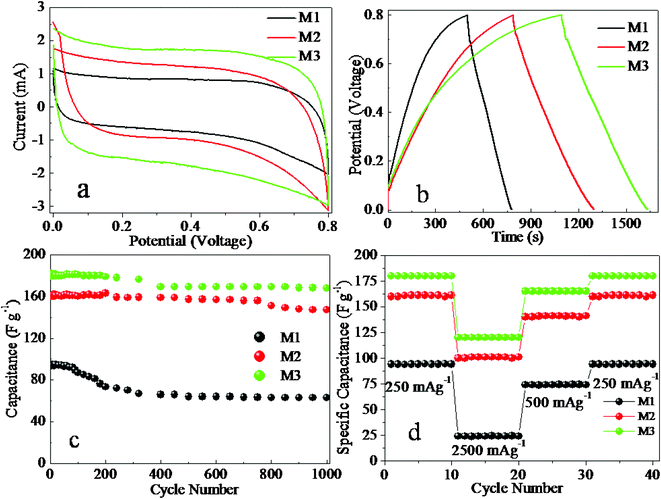 | ||
| Fig. 6 (a) CV curves vs. Ag/AgCl, 5 mV s−1; (b) CP curves, 250 mA g−1; (c) variation of specific capacitance with cycle number at 250 mA g−1; (d) specific capacitance at various charge-discharge current densities. | ||
The variation of specific capacitance as a function of cycle number is shown in Fig. 6c at 250 mA g−1, and reveals that the plate NiMn2O4 electrode has good recycle properties for electrochemical capacitors. From Fig. 3 in the ESI†, the charge–discharge voltage profiles of the first 10 cycles for the plate NiMn2O4 electrode, and the coulombic efficiency is very high for each cycle. It is only approximately 6.5% loss of specific capacitance after 500 cycles and 7.3% loss even after 1000 cycles, which might cause the decomposition of the porous plate structure. Compared with plate NiMn2O4, specific capacitance of the porous bipyramid NiMn2O4 material electrode only can be maintained at 67.0% after 1000 cycles. From ESI, Fig. 4c, there are few changes of NiMn2O4 porous plate structure after 1000 charge–discharge cycles, while the other structures changed into formless particles (ESI, Fig. 4a–b†), and the porous plate structure might offer a stable structure for ion intercalation/extraction, which might improve the cycle life of the electrode.3 Specific capacitance at various charge–discharge current densities were also measured, we also found the porous plate NiMn2O4 electrode also maintained a large specific capacitance 122 F g−1, 2500 mA g−1, while others decreased largely under the same condition. These data indicate that the porous plate NiMn2O4 electrode serves as a good electroactive material with its high power density and recycle stability.
We propose a possible mechanism (eqn (1)) to explain the intercalation/deintercalation of Na+ in NiMn2O4 materials.
| NiMn2O4 + Na+ + e− ⇌ NaNiMn2O4 | (1) |
To understand the electrode kinetics, the activation energies of the as-prepared materials for Na+ intercalation were estimated by electrochemical impedance spectra (EIS). Fig. 5 of the ESI† show the EIS of the electrodes at different temperatures. In general, the impedance curves present two partially overlapped semicircles in the high- and medium-frequency regions and an inclined line in the low-frequency region. An equivalent circuit used to fit the impedance curve is given in Fig. 6 of the ESI†, which is similar to the circuit employed for the working electrode of supercapacitor. The EIS data can be fitted by a bulk solution resistance Rs, a charge-transfer Rct and a pseudocapacitive element Cp from the redox process of NiMn2O4, and a constant phase element (CPE) to account for the double-layer capacitance. The activation energies (Ea) are calculated, which can be seen in the experiment calculation section and Fig. 6–7 of the ESI†. The lowest activation energy of porous plate NiMn2O4 electrode indicates the shorter diffusion route for ion intercalation. This surface-interface character of the porous plate structure might decrease the polarization of the electrode, and thus increases the capacity.
In summary, porous structured NiMn2O4 materials were successfully synthesized by calcinations of oxalate precursors without any template or surfactant. The measurement of electrochemical properties of porous structured NiMn2O4 materials is an important work, which illustrates that the porous plate NiMn2O4 materials can be applied as outstanding electroactive materials for supercapacitors. We also find that the three porous structured NiMn2O4 materials have different electrochemical properties. It is a good example to prove that physical-chemical properties are dependent on material structure, which encourages scientists to control the morphology of materials precisely to control their performance.
Acknowledgements
This work is supported by the National Natural Science Foundation of China (21071006, 21003001 & 21105002), Henan Province of International Science & Technology Cooperation (11430051003) and the projects of Ministry of Education of returned overseas students.References
- H. Pang, Q. Y. Lu, Y. C. Li and F. Gao, Chem. Commun., 2009, 7542–7544 RSC.
- H. Pang, Q. Y. Lu, Y. Z. Zhang, Y. C. Li and F. Gao, Nanoscale, 2010, 2, 920–922 RSC.
- H. Pang, B. Zhang, J. Du, J. Chen, J. S. Zhang and S. Li, RSC Adv., 2012, 2, 2257–2261 RSC.
- H. Pang, F. Gao and Q. Y. Lu, Chem. Commun., 2009, 1076–1078 RSC.
- H. Pang, Q. Y. Lu, J. J. Wang, Y. C. Li and F. Gao, Chem. Commun., 2010, 46, 2010–2012 RSC.
- H. Pang, F. Gao and Q. Y. Lu, Chem. Commun., 2011, 47, 11772–11774 RSC.
- X. G. Peng, L. Manna, W. D. Yang, J. Wickham, E. Scher, A. Kadavanich and A. P. Alivisatos, Nature, 2000, 404, 59–61 CrossRef CAS.
- W. U. Huynh, J. J. Dittmer and A. P. Alivisatos, Science, 2002, 295, 2425–2427 CrossRef CAS.
- (a) Y. Xia, P. Yang, Y. Sun, Y. Wu, B. Mayers, B. Gates, Y. Yin, F. Kim and H. Yan, Adv. Mater., 2003, 15, 353 CrossRef CAS; (b) X. Cao, H. Zeng, M. Wang, X. Xu, M. Fang, S. Ji and L. Zhang, J. Phys. Chem. C, 2008, 112, 5267–5270 CrossRef CAS; (c) R. Gao, L. Yin, C. Wang, Y. Qi, N. Lun, L. Zhang, Y.-X. Liu, L. Kang and X. Wang, J. Phys. Chem. C, 2009, 113, 15160 CrossRef CAS; (d) Y. Wang, H. Xia, L. Lu and J. Lin, ACS Nano, 2010, 4, 1425 CrossRef CAS; (e) W. Liu, Z.-M. Cui, Q. Liu, D.-W. Yan, J. Y. Wu, H. J. Yan, Y. L. Guo, C. R. Wang, W. G. Song, Y.-Q. Liu and L. J. Wan, J. Am. Chem. Soc., 2007, 129, 12922 CrossRef CAS.
- M. H. Huang, S. Mao, H. Feick, H. Yan, Y. Wu, H. Kind, E. Weber, R. Russo and P. Yang, Science, 2001, 292, 1897 CrossRef CAS.
- M. Law, L. E. Greene, J. C. Johnson, R. Saykally and P. Yang, Nat. Mater., 2005, 4, 455 CrossRef CAS.
- Y. Li, B. Tan and Y. Wu, Nano Lett., 2008, 8, 265 CrossRef CAS.
- Y. Qin, X. Wang and Z. L. Wang, Nature, 2008, 451, 809 CrossRef CAS.
- L. Qu, L. Dai, M. Stone, Z. Xia and Z. L. Wang, Science, 2008, 322, 238 CrossRef CAS.
- T. Zhao, J. Wu and J. Huang, J. Am. Chem. Soc., 2009, 131, 3158 CrossRef.
- H. Zeng, P. M. Rice, S. X. Wang and S. H. Sun, J. Am. Chem. Soc., 2004, 126, 11458–11459 CrossRef CAS.
- S. H. Sun, H. Zeng, D. B. Robinson, S. Raoux, P. M. Rice, S. X. Wang and G. X. Li, J. Am. Chem. Soc., 2004, 126, 273–279 CrossRef CAS.
- M. M. Thackeray, W. I. F. David, P. G. Bruce and J. B. Goodenough, Mater. Res. Bull., 1983, 18, 461 CrossRef CAS.
- J. M. Tarascon, W. R. McKinnon, F. Coowar, T. N. Bowmer, G. Amatucci and D. Guyomard, J. Electrochem. Soc., 1994, 141, 1421 CrossRef CAS.
- W. Liu, K. Kowal and G. C. Farrington, J. Electrochem. Soc., 1998, 145, 459 CrossRef CAS.
- X. Yang, W. Tang, Z. Liu, Y. Makita and K. Ooi, J. Mater. Chem., 2002, 12, 489 RSC.
- P. G. Bruce, B. Scrosati and J. M. Tarascon, Angew. Chem., Int. Ed., 2008, 47, 2930 CrossRef CAS.
- S. T. Myung, K. S. Lee, D. W. Kim, B. Scrosati and Y. K. Sun, Energy Environ. Sci., 2011, 4, 935 CAS.
- O. K. Park, Y. Cho, S. Lee, H. C. Yoo, H. K. Song and J. Cho, Energy Environ. Sci., 2011, 4, 1621 CAS.
- Q. T. Qu, L. J. Fu, X. Y. Zhan, D. Samuelis, J. Maier, L. Li, S. Tian, Z. H. Li and Y. P. Wu, Energy Environ. Sci., 2011, 4, 3985–3990 CAS.
- Z. J. Zhang, Z. L. Wang, B. C. Chakoumakos and J. S. Yin, J. Am. Chem. Soc., 1998, 120, 1800–1804 CrossRef CAS.
- J. P. Chen, C. M. Sorensen, K. J. Klabunde, G. C. Hadjipanayis, E. Devlin and A. Kostikas, Phys. Rev. B: Condens. Matter, 1996, 54, 9288–9296 CrossRef CAS.
- Y. Xie, J. X. Huang, B. Li, Y. Liu and Y. T. Qian, Adv. Mater., 2000, 12, 1523–1526 CrossRef CAS.
- J. T. Sampanthar and H. C. Zeng, J. Am. Chem. Soc., 2002, 124, 6668–6675 CrossRef CAS.
- P. C. Ohara, J. R. Heath and W. M. Gelbart, Angew. Chem., Int. Ed. Engl., 1997, 36, 1078–1080 CrossRef CAS.
- Y. Ren, Z. Ma and P. G. Bruce, CrystEngComm, 2011, 13, 6955–6959 RSC.
- V. Subramanian, H. Zhu, R. Vajtai, P. M. Ajayan and B. Wei, J. Phys. Chem. B, 2005, 109, 20207–20214 CrossRef CAS.
- S. Sarangapani, B. V. Tilak and C. P. Chen, J. Electrochem. Soc., 1996, 143, 3791–3799 CrossRef CAS.
- R. N. Reddy and R. G. Reddy, J. Power Sources, 2004, 132, 315–320 CrossRef CAS.
- B. E. Conway, Electrochemical Supercapacitors; Kluwer Academic/Plenum Publishers: New York, 1999 Search PubMed.
- C. C. Hu and C. C. Wang, Electrochem. Commun., 2002, 4, 554–559 CrossRef CAS.
- A. Meenakshisundaram, N. Gunasekaran and V. Srinivasan, Phys. Status Solidi A, 1982, 69, K15–19 CrossRef CAS.
- J. B. Goodenough and A. L. Loeb, Phys. Rev., 1955, 98, 391–408 CrossRef CAS.
- S. L. Kuo and N. L. Wu, Electrochem. Solid-State Lett., 2005, 8, A495–499 CrossRef CAS.
Footnote |
| † Electronic supplementary information (ESI) available: Experimental detail, electrode preparation, characterization and calculation. See DOI: 10.1039/c2ra20245j |
| This journal is © The Royal Society of Chemistry 2012 |
