Facile controlled growth of silica on carbon spheres and their superior electrochemical properties
Jie
Shu
*a,
Rui
Ma
a,
Miao
Shui
a,
Dongjie
Wang
a,
Nengbing
Long
a,
Yuanlong
Ren
a,
Ruifeng
Zhang
a,
Jinhan
Yao
b,
Xinbiao
Mao
b,
Weidong
Zheng
a and
Shan
Gao
a
aFaculty of Materials Science and Chemical Engineering, Ningbo University, Ningbo, Zhejiang 315211, P. R. China. E-mail: sergio_shu@hotmail.com; shujie@nbu.edu.cn (Dr Jie Shu); Fax: +86-574-87609987; Tel: +86-574-87600787
bCollege of Chemical Engineering and Materials Science, Zhejiang University of Technology, Hangzhou, 310032, Zhejiang Province, People's Republic of China
First published on 18th April 2012
Abstract
In this paper, silica coated carbon sphere composites were synthesized by a facile hydrothermal method. During the preparation, carbon@silica composites were formed by hydrolysis and deposition of TEOS on the surface of carbon spheres. XRD patterns show that this coating layer is composed of crystallized SiO2. When different amounts of TEOS were added, carbon@silica composites show different surface morphologies formed by silica nucleation and growth, spreading into a thinly coated layer, repeatedly. These varied silica coating layers have a great effect on the SEI film formation and electrochemical properties of the carbon@silica composites. The surface morphology and onset formation voltage of the surface film are greatly dependent on the surface morphology and structure of carbon@silica composites. Similarly, the lithiation and delithiation behaviors are obviously affected by this silica coating layer. Carbon@silica composites can deliver a reversible capacity of 351 mAh·g−1 in 0.0–3.0 V after 30 cycles, which is higher than that of the pristine carbon spheres. The extra capacity mainly comes from the Li-storage in the micropores and disordered graphene layers after silica coating. By broadening the electrochemical cycling window, a higher reversible capacity of 511 mAh·g−1 can be delivered in the voltage range between −15 mV and 3.0 V. The excess capacity in the low voltage region is mainly associated with additional Li-storage in micropores. It indicates that carbon@silica composites are promising anode materials for lithium-ion batteries.
1. Introduction
High performance lithium storage materials have stimulated research all over the world. Attributed to the peculiar structure in one-, two- and three-dimensions, nanostructured materials consistently show unique physical and chemical properties for energy storage and conversion. For obtaining peculiar properties, the controlled growth technique is an important method for preparing nanostructured materials with different morphologies, such as wires, spheres, tubes, rods and belts. X. W. Lou recently reported the preparation of SnO2 nanoboxes, nanosheets, nanowires and hollow spheres as lithium storage materials by using hard template techniques.1–4 A. M. Belcher described the self-assembly of nanostructured materials by virus chains as soft template.5–8 In the preparation process, silica is a traditional template material for nanostructured materials synthesis. It can be found elsewhere that the formation and removal of silica template is a facile process. Based on previous reports, it is known that many inorganic materials with different morphologies can be obtained by using silica as a template, such as mesoporous silver and carbon.9–12 To fabricate different structures for objective samples, G. D. Stucky and D. Y. Zhao reported the controlled preparation and structural characterization of silica with different morphologies.13–15Silica is also used as a coating material for cathode decoration in lithium-ion batteries. The interface and thermal stabilities of cathode materials can be obviously improved by this silica layer. J. Q. Zhang et al. concluded that metal ion dissolution from cathode materials, such as LiNi0.5Mn1.5O4, LiNi0.8Co0.2O2, LiMn2O4 and LiFePO4, can be effectively suppressed due to the existence of a protective silica layer.16–19 As a result, the capacity retention of cathode materials can be improved after long-term cycles. However, the formation mechanism of a silica layer on lithium storage materials is rarely reported, and it is probably different from that of the pure silica template.
As mentioned above, a silica coating layer is always used to decorate cathode materials for preventing interface breakdown and dissolution. However, the solid electrolyte interphase (SEI) film on cathode materials can be also changed by this coating layer. It is well-known that an SEI film can form on the surface of active materials during the charge-discharge process, especially during the 1st cycle. Compared to SEI film on cathode materials, the SEI film on anode materials induces larger irreversible capacity and worse thermal stability due to the solvent reduction decomposition in the first discharge process. The lithium storage ability can be improved by various metal or non-metal coating layers.20–26 Therefore, surface decoration for anode materials is also an essential route to improve the electrochemical properties of lithium-ion batteries. To our knowledge, few publications about silica coating on the anode material can be found.
In this paper, the controlled growth of silica on carbon spheres is prepared by a facile hydrothermal method. The formation mechanism of silica on carbon spheres is described in detail according to the experimental results. It is found that the deposition of silica on carbon spheres proceeds through silica-core formation, growth and then integration into a thin coating layer. In addition, the electrochemical behavior of carbon@silica composites are also discussed. It is obvious that not only the irreversible capacity but also working potentials can be changed by introducing the silica coating layer.
2. Experimental
2.1. Preparation and characterization of carbon@silica composites
As described in detail elsewhere, carbon spheres can be made by using sugar as a precursor.27 In the experiment, 2 g sugar is dissolved in 90 mL distilled water to form a colorless solution. To prepare carbon spheres, the sugar solution is put into a 100 mL Teflon-lined stainless steel autoclave and maintained at 180 °C for 12 h. The resulting product is filtered and washed, then dried at 120 °C for 12 h. Carbon spheres are obtained by calcining the black product in an argon-purged tube furnace at 1000 °C for 12 h.To fabricate carbon@silica composites, 0.2 g carbon spheres are dispersed in 85 mL ethanol solution. Then, an appropriate amount of tetraethylorthosilicate (TEOS) and distilled water are added into the suspension drop by drop. The weight percent of SiO2 in carbon@silica composite is controlled by using different addition amounts of TEOS. The mixed solution is sealed in a Teflon-lined stainless steel autoclave for hydrothermal reaction. After hydrolyzing at 180 °C for 5 h, the obtained powders are calcined at 800 °C for 2 h in Ar atmosphere. The as-prepared samples are carbon@silica composites. Here, the molar amounts of TEOS are 0.00, 0.04, 0.10, 0.20, 1.00 and 2.00 mmol for preparing six kinds of carbon@silica composites. In order to facilitate discussion, carbon@silica composites prepared by using 0.00, 0.04, 0.10, 0.20, 1.00 and 2.00 mmol TEOS are respectively named as sample A, sample B, sample C, sample D, sample E and sample F in the following section.
The surface morphologies of carbon@silica composites are observed with a XL30 S-FEG field emission scanning electron microscopy (SEM). The X-ray diffraction (XRD) patterns for as-prepared samples are collected with a Bruker D8 Focus diffractometer using nickel-filtered Cu-Kα radiation (λ = 1.5418 Å). Fourier transform infrared (FTIR) spectra are recorded by a Shimadzu FTIR-8900 infrared spectrophotometer from 350 to 2500 cm−1. Raman spectra are taken on a SPEX-1403 Raman spectrophotometer (SPEX, USA) from 400 to 2500 cm−1.
2.2. Fabrication and testing of electrode and battery
The working electrodes for electrochemical analysis are prepared by coating a mixed slurry containing 80 wt% carbon@silica material, 10 wt% acetylene black and 10 wt% polyvinylidene fluoride dissolved in N-methylpyrrolidine onto a copper foil with a doctor blade technology. After coating, the wet film is dried in a vacuum oven at 120 °C for 24 h, and then cut into discs with a diameter of 15 mm. Before battery assembly, the working electrode is dried in a vacuum oven at 120 °C for 24 h to avoid possible contamination from water and other absorbed impurities.Simulated two-electrode batteries for repeated cycles are assembled in an Ar-filled Etelux glove box by using metal lithium disc as counter electrode, 1 mol L−1 LiPF6 in a mixture of ethylene carbonate (EC) and dimethyl carbonate (DMC) as electrolyte, and Whatman glass fiber as separator. For simulated battery assembly, the moisture content and oxygen level in the glove box are controlled below 5 ppm. Galvanostatic charge-discharge cycles are recorded on multichannel Land Battery Test System. Electrochemical impedance spectroscopy (EIS) results of different samples are collected on a CHI 660D electrochemical working station in the frequency range between 100 KHz and 0.01 Hz with an amplitude of 5 mV. In this experiment, all the electrochemical experiments are carried out at 25 °C.
3. Results and discussion
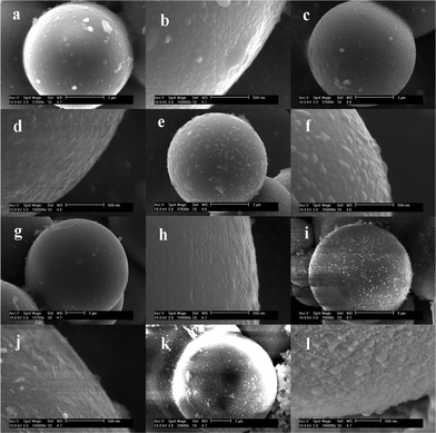
Fig. 1a–l show the SEM images of the surface morphologies for carbon@silica composites with different silica coating contents. It is obvious that the silica content in carbon@silica composites is controlled by the amount of TEOS added in the experiment. As-prepared carbon spheres before silica coating, named sample A, have a clean and smooth surface as presented in Fig. 1a and 1b. After the addition of 0.04 mmol TEOS, some nano-sized silica particles with a diameter of 10–20 nm distribute uniformly on the surface of the carbon spheres as shown in Fig. 1c and 1d. When the molar amount of TEOS is increased from 0.04 mmol to 0.10 mmol and then to 0.20 mmol, the silica particles become larger and merge into a smooth coating layer as exhibited in Fig. 1e–h. It indicates that the formation of the silica coating layer on carbon spheres is associated with nano-sized SiO2 particle nucleation, growth and spreading processes. Increasing the molar amount of TEOS to 1.00 mmol, the surface of carbon spheres is deposited by nano-sized SiO2 islands again as shown in Fig. 1i and 1j. Obviously, these silica islands are formed independently on the surface of the initial single coating layer. When 2.00 mmol TEOS is added into the Teflon-lined stainless steel autoclave, the independent silica islands disappear and the surface of the carbon spheres becomes smooth again. It is believed that the second silica coating layer is formed by hydrolysis of much more TEOS and lies on the outside of the initial silica layer. Based on the above analysis, it is known that core carbon spheres can be completely coated by silica when the molar amount of TEOS is equal to or more than 0.2 mmol. The formation of the silica coating layer is related to a gradual deposition process by hydrolysis of TEOS under hydrothermal conditions. Fig. 2 shows the schematic view of the formation of the silica coating layer on the surface of the carbon sphere. In a typical hydrothermal reaction, TEOS is absorbed on the surface of the carbon spheres and hydrolyzed into Si(OH)4, then changes into nano-sized SiO2 particles after heat-treatment. This deposition process includes silica nucleation and growth, spreading into a thin coating layer, which is repeated to form double layers.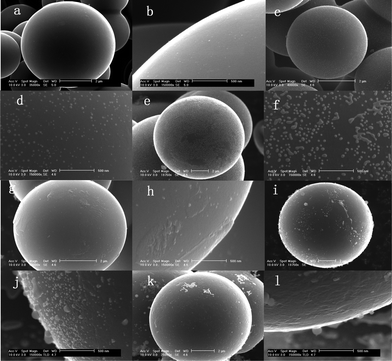 | ||
| Fig. 1 SEM images of as-prepared carbon@silica composites prepared by hydrolysis of TEOS with different molar amounts; (a) and (b): 0.00 mmol; (c) and (d): 0.04 mmol; (e) and (f): 0.10 mmol; (g) and (h): 0.20 mmol; (i) and (j): 1.00 mmol; (k) and (l): 2.00 mmol. | ||
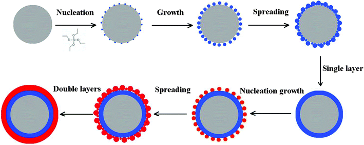 | ||
| Fig. 2 Schematic view of the formation mechanism of silica coating layer on the surface of carbon spheres. | ||
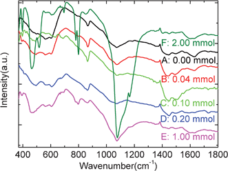
Fig. 3a–c present the XRD, FTIR and Raman patterns of the pristine carbon sphere and as-prepared carbon@silica composites. XRD patterns show that prepared carbon spheres contain typical disordered carbon with two broad peaks at around 22.9° and 43.6°. In the XRD pattern of carbon@silica composites prepared by the addition of 0.04 mmol TEOS, only a small diffraction peak at 26.6° related to the (101) reflection from SiO2 can be detected except for the broad Bragg reflections from disordered carbon structure. With the increase of TEOS, the (101) peak becomes sharper as shown in Fig. 3a. When the molar amount of TEOS is equal to or more than 1.00 mmol, it is obvious that some diffraction peaks located at 20.8°, 26.6°, 36.5°, 39.5°, 50.1°, 60.0° and 68.0° appear in the XRD patterns. They are in good agreement with the JCPDS card No 87-2096, indicating that a crystallized silica coating is present on the surface of the carbon spheres. In most previous reports, active materials coated with amorphous silica are studied as electrode materials for lithium-ion batteries.16–19 It is found that the structural and electrochemical stabilities of active materials can be improved by this amorphous coating layer. However, crystallized silica coating layers are rarely found in the energy storage and conversion field. It is expected that the electrochemical properties of carbon spheres can be also enhanced by this crystallized silica coating layer. Fig. 3b shows the FTIR spectra of carbon@silica composites with different silica coating contents. The vibration bands for pristine carbon spheres located at 1635, 1590, 1401, 1349, 1185, 1109, 1071, 1042, 667, 608 and 562 cm−1 can be assigned to O–H bending, C![[double bond, length as m-dash]](https://www.rsc.org/images/entities/char_e001.gif) O stretching, CC stretching, COO− stretching, C–H bending, C–H scissors deformation, C–O–C stretching, C–O stretching, CO2 bending, O–C–O bending and N–O wagging, respectively.27–32 These functional groups are probably attributed to the residual dangling bond, absorbed water, and air molecules. After silica coating, extra vibration bands located at 1166, 799, 780, 696, 521, 467 and 397 cm−1 can be observed in Fig. 3b, which are ascribed to Si–O–Si stretching out of phase motion of adjacent oxygen atoms, Si–O–Si bending, Si–C wagging, Si–O bending, Si–Si stretching, Si–O out of plane deformation and Si–OH wagging, respectively.33–37 These vibration peaks become more and more sharp with increasing molar amount of TEOS. It also confirms that the silica coating layer on the surface of carbon spheres is formed with the gradual hydrolysis and deposition of TEOS. Moreover, the appearance of Si–C and Si–Si bonds indicates that there are some redox reactions between the carbon sphere and silica coating layer during hydrothermal and heat-treatment processes. Fig. 3c shows the Raman spectra of carbon@silica composites with different silica coating contents between 1000 and 2000 cm−1. Two vibration modes can be observed at 1370 and 1600 cm−1, which correspond to the disordered and graphitic structure of the carbon spheres. These two bands are assigned to D and G bands. After silica coating, the positions of the two bands move to 1370, 1370, 1365, 1363, 1359 cm−1 for D band (A1g) and 1597, 1593, 1593, 1590, 1589 cm−1 for G band (E2g), respectively. It is obvious that silica coating induces the red shift of Raman active bands. The D and G bands shift to lower positions with increasing silica coating content. Furthermore, the integrated intensity ratios of IG/ID are calculated to be 1.195, 1.210, 1.211, 1.227, 1.230 and 1.231 for sample A, B, C, D, E and F, respectively. These values increase with increasing amounts of TEOS from 0.00 to 2.00 mmol. It suggests that the graphitization degree of carbon spheres is improved with the addition of TEOS. The improvement of graphitization degree in carbonaceous structure is probably ascribed to the rearrangement of microstructure of carbon spheres induced by silica coating.
O stretching, CC stretching, COO− stretching, C–H bending, C–H scissors deformation, C–O–C stretching, C–O stretching, CO2 bending, O–C–O bending and N–O wagging, respectively.27–32 These functional groups are probably attributed to the residual dangling bond, absorbed water, and air molecules. After silica coating, extra vibration bands located at 1166, 799, 780, 696, 521, 467 and 397 cm−1 can be observed in Fig. 3b, which are ascribed to Si–O–Si stretching out of phase motion of adjacent oxygen atoms, Si–O–Si bending, Si–C wagging, Si–O bending, Si–Si stretching, Si–O out of plane deformation and Si–OH wagging, respectively.33–37 These vibration peaks become more and more sharp with increasing molar amount of TEOS. It also confirms that the silica coating layer on the surface of carbon spheres is formed with the gradual hydrolysis and deposition of TEOS. Moreover, the appearance of Si–C and Si–Si bonds indicates that there are some redox reactions between the carbon sphere and silica coating layer during hydrothermal and heat-treatment processes. Fig. 3c shows the Raman spectra of carbon@silica composites with different silica coating contents between 1000 and 2000 cm−1. Two vibration modes can be observed at 1370 and 1600 cm−1, which correspond to the disordered and graphitic structure of the carbon spheres. These two bands are assigned to D and G bands. After silica coating, the positions of the two bands move to 1370, 1370, 1365, 1363, 1359 cm−1 for D band (A1g) and 1597, 1593, 1593, 1590, 1589 cm−1 for G band (E2g), respectively. It is obvious that silica coating induces the red shift of Raman active bands. The D and G bands shift to lower positions with increasing silica coating content. Furthermore, the integrated intensity ratios of IG/ID are calculated to be 1.195, 1.210, 1.211, 1.227, 1.230 and 1.231 for sample A, B, C, D, E and F, respectively. These values increase with increasing amounts of TEOS from 0.00 to 2.00 mmol. It suggests that the graphitization degree of carbon spheres is improved with the addition of TEOS. The improvement of graphitization degree in carbonaceous structure is probably ascribed to the rearrangement of microstructure of carbon spheres induced by silica coating.
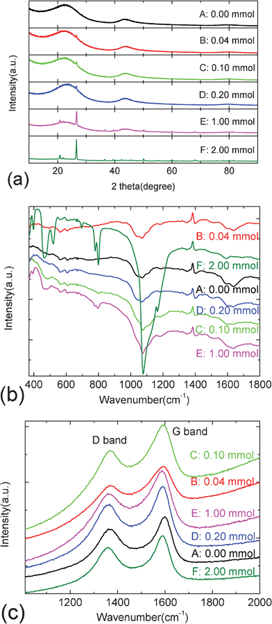
Fig. 4a–d show the charge-discharge curves, corresponding dQ/dV curves and EIS patterns of various carbon@silica composites with different silica coating contents. The charge-discharge curves of various carbon@silica composites are shown in Fig. 4a. It can be found that different carbon@silica composites show different electrochemical behaviors. The discharge and capacities of carbon@silica composites are also changing with different silica coating contents. Although sample F prepared by the addition of 2.00 mmol TEOS shows the largest initial discharge capacity of 622 mAh·g−1, the reversible capacity is the smallest one among all the samples. Viewed from Fig. 4a, it is clear that sample E shows the best electrochemical properties and highest reversible capacity. With the amount of added TEOS between 0.00 and 1.00 mmol, the lithium storage properties of carbon@silica composites are gradually improved with increasing silica coating content. To describe the lithium storage mechanism, the dQ/dV curves are shown in Fig. 4b. It shows the first and third dQ/dV curves of carbon spheres before and after silica coating at a charge-discharge rate of 0.1 C. There are several oxidation and reduction peaks corresponding to Li-uptake/release processes in the dQ/dV plots of carbon@silica composites. It is well-known that the first reduction peak is always associated with the electrolyte decomposition and SEI film formation. The onset voltage of this peak is determined by the electronic conductivity and surface morphology of the sample. It is obvious that the first reduction peak is irreversible and shifts negatively with the increase of silica coating content. It may be associated with the low electronic conductivity of the silica coating layer. However, there is an abnormal irreversible behavior when the amount of TEOS added is equal to 1.00 mmol. The initial electrolyte reduction decomposition peak appears at 0.78 V for sample E, which is similar to that of the as-prepared carbon spheres. To discover this abnormal phenomenon, EIS experiments were performed using open circuit states for the carbon@silica composites before and after silica coating as shown in Fig. 4c and 4d. The full and local EIS patterns show that the existence of nano-sized silica particles on the surface is beneficial to decrease the charge transfer impedance of carbon@silica composites, such as sample B, C and E. In contrast, the carbon@silica composites without independent silica islands on surface have higher charge transfer impedance as shown in Fig. 4c and 4d. Although the electronic conductivity of carbon@silica composites is associated with the silica coating content, the charge transfer impedance is related to the existence of nano-sized silica particles. It indicates that the surface morphology of the sample will change the electrochemical behavior of carbon@silica composites. Based on above analysis, the abnormal onset voltage of the initial irreversible reduction peak for sample E is probably attributed to the peculiar surface morphology. Viewed from the dQ/dV profiles in Fig. 4b, it is also obvious that the oxidation reaction takes place at a different voltage for different carbon@silica composites. It indicates that the existence of the silica coating layer on the surface may change the lithium storage mechanism in the carbon spheres. Therefore, it is necessary to find the effect of surface morphology and structure on the electrochemical behavior of carbon@silica composites.
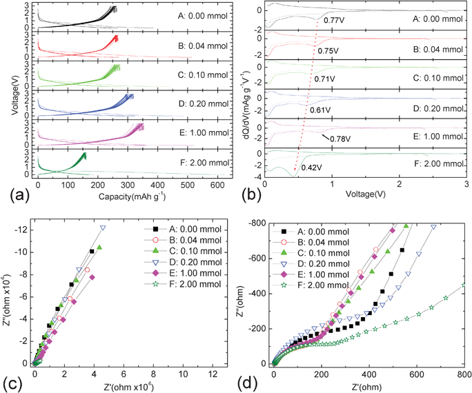 | ||
| Fig. 4 Charge-discharge curves (a), corresponding dQ/dV plots (b) and EIS results (c, d) of carbon@silica composites. | ||
Fig. 5 shows the relations between the pristine surface morphology and SEI film formation for different carbon@silica composites after a discharge process to 0.0 V. Compared with that of the pristine samples, it can be found that most carbon@silica composites show different surface morphologies after electrochemical cycles. The morphology of the SEI film can not follow the pristine surface morphology of the carbon@silica composites Although samples A, B and D have different surface characteristics before lithiation, they show similar surface morphologies after a discharge process to 0.0 V. It seems that their surfaces are smooth after SEI film coating. In contrast, the surface of samples C and F are rough and covered by island-like SEI films. The surface of sample E is quite different from that of the other six samples. Irregular flaky and flocculent deposits are the main products on the surface of sample E after the initial electrochemical reduction reactions. It confirms that different surface morphologies and structures will induce different SEI film deposition processes. FTIR results in Fig. 6 show the vibration bands of various lithiated samples, which are similar to those of the as-prepared samples, except for the sharp band at 865 cm−1. Based on previous reports, it is known that the positions of most vibration bands assigned to alkyl carbonates are similar to those reflected from the residual dangling bond, absorbed water and air molecules on carbonaceous materials.27,38–40 As a result, partial infrared characteristic signals are concealed by these contaminants on the surface of carbon@silica composites. The new infrared active band at 865 cm−1 can be observed in the FTIR patterns for all the lithiated samples, which is attributed to the CO32− bending in Li2CO3. It indicates that there are lots of Li2CO3 in the composition of the SEI film. Although the surface morphologies of SEI films on different samples are quite different, the compositions of these SEI films are similar to each other as proved by the FTIR patterns in Fig. 6. It suggests that the surface morphology probably does not have an effect on the one-/two-electron reaction mechanism for SEI film formation but has great effect on the polarization of electrochemical reactions. As a result, the abnormal onset voltage of sample E can be observed in Fig. 4b.
 | ||
| Fig. 5 SEM images of carbon@silica composites after 20 cycles. The carbon@silica composites are prepared by hydrolysis of TEOS with different molar amounts; (a) and (b): 0.00 mmol; (c) and (d): 0.04 mmol; (e) and (f): 0.10 mmol; (g) and (h): 0.20 mmol; (i) and (j): 1.00 mmol; (k) and (l): 2.00 mmol. | ||
 | ||
| Fig. 6 FTIR spectra of carbon@silica composites after cycles. | ||
Fig. 7a–f show the electrochemical properties of carbon@silica composites at 0.1 C in the voltage range 0.0–3.0 V. Although there are different polarizations observed for different carbon@silica composites as shown in Fig. 7a and 7b, all the charge-discharge curves of the samples are composed of three distinct parts, I, II and III regions. It indicates that there are three different Li-storage mechanisms for different lithiation or delithiation levels. Viewed from the charge curves, it is obvious that the first plateau appears below 0.1 V (region III), the second long region locates in the voltage range 0.1–1.2 V (region II), followed by a steep slope above 1.2 V (region I). Based on previous reports, these three different plateaus correspond to Li-storage in micropores, Li-insertion into disordered graphene layers and Li-binding with dangling bonds.41–43 As reported, the 1st coulombic efficiency of samples can be probably improved by the coating layer.44 This is because the irreversible decomposition of the electrolyte and ion dissolution from the active material may be effectively suppressed. In this experiment, the evolution of the initial coulombic efficiency of the samples after silica coating are not consistent with the previous results as shown in Fig. 7c. It is obvious that the 1st coulombic efficiency of carbon@silica composites drops from 63.3% to 52.1% after the addition of 0.04 mmol TEOS, and then increases to 61.3% by the addition of 1.00 mmol TEOS, finally declining to 25.6% when the molar amount of TEOS is equal to 2.00 mmol. The existence of the silica coating layer may be responsible for this abnormal phenomenon. This is because partial nano-sized silica will react with lithium and result in irreversible capacity loss during the first discharge process.45,46 On the other hand, the shortening or lengthening of Li-storage regions in the charge-discharge curves indicates different trapped and dead lithium contents in the structure for different carbon@silica composites. It should also be responsible for the irreversible capacity in the first cycle. After 30 cycles, high coulombic efficiency can be achieved for all the samples as shown in Fig. 7c. It suggests that most irreversible reactions only appear in the first charge-discharge cycle. Comparing the discharge curve with the recharge one, it is found that additional capacity after silica coating mainly comes from the Li-storage in regions II and III. Fig. 7d shows the relations between lithiation regions (I, II and III) and amount of TEOS added for the first electrochemical cycle. It can be seen that the capacity about Li-storage in micropores in moderate and low voltage ranges (regions II and III) varies with the added amount of TEOS. Among all the carbon@silica composites, sample E shows the largest capacity in regions II and III, indicating the improved Li-storage behavior in disordered graphene layers and micropores by the silica coating layer. According to the Raman spectra, it is known that the graphization degree of carbon spheres can be improved after silica coating. It indicates that the graphene layers in the structure are enhanced, which induces more lithium ion storage in graphene layers. Therefore, the lithiation plateau in region II is longer than this original one. As reported, smaller micropores show higher electromotive force value and larger Li-storage capacity below 0.1 V.47,48 It is suggested that the structure of the micropore may be changed by the silica coating layer in the experiment. Some large micropores may be filled and blocked into smaller micropores for Li-storage, which is probably similar to the results after a chemical vapor deposition of acetylene on carbon spheres.48 Besides, it is also reported that the average energy of unoccupied orbitals of hard carbon can be decreased by modification with oxide, and then the lithiation-delithiation voltages, especially for region III, are obviously increased.49 Based on this analysis, it is known that changing the size of micropores or reducing the average energy of unoccupied orbital both can bring an increase of Li-storage capacity in micropores in the region III by surface modification with silica. As a result, the silica coating layer plays an important role in the increase of reversible capacity. Moreover, the capacity in region III increases with increasing silica coating content, but the capacity in region II is almost maintained as shown in Fig. 7d. It indicates that the structure of the micropores are gradually changed by the silica coating layer. When too much silica is coated on carbon spheres, the reversible capacity of sample F shows a great decrease compared to that delivered by sample D or E. It is probably attributed to poor electronic conductivity and high charge transfer impedance from thick coating film with double silica layers, which induces high polarization and then the lithiation plateau III moves to the voltage range below 0.0 V. Fig. 7e exhibits the cycling properties of carbon@silica composites with different silica coating contents. The pristine carbon spheres exhibit a reversible Li-storage capacity of 263 mAh·g−1 after 30 cycles. After coating with silica particles on carbon spheres, no obvious change can be observed for the reversible charge capacity for sample B and C. The reversible Li-storage capacity is increased when a continuous silica coating layer is formed on the surface of carbon spheres. Compared to the as-prepared carbon spheres, a reversible capacity of 351 mAh·g−1 can be delivered by sample E after 30 cycles. However, the reversible capacity of carbon@silica composites decreases drastically when the amount of TEOS added is equal to or more than 2.00 mmol. This is because the surface of sample F is coated with a dense silica layer. It is well-known that bulk or dense SiO2 is an inactive material for Li-storage. Therefore, the increase of SiO2 content in carbon@silica composites may counteract the improvement in capacity from Li-storage in micropores. In addition, low electronic conductivity of SiO2 may bring large polarization, which shortens the Li-storage plateau in region III. Fig. 7f compares the rate performances of two silica coated carbon spheres with the as-prepared pristine sample. It can be found that carbon@silica composites exhibit excellent kinetic properties at different rates. Especially for sample E, it shows better rate performance than that of the pristine carbon spheres at low and moderate rates (0.1 C, 1 C and 2 C) and excellent cycling properties at super-high rates (6 C and 20 C). In addition the silica layer is a kind of thermal insulator, which may improve the safety of active material as anode for lithium-ion batteries.
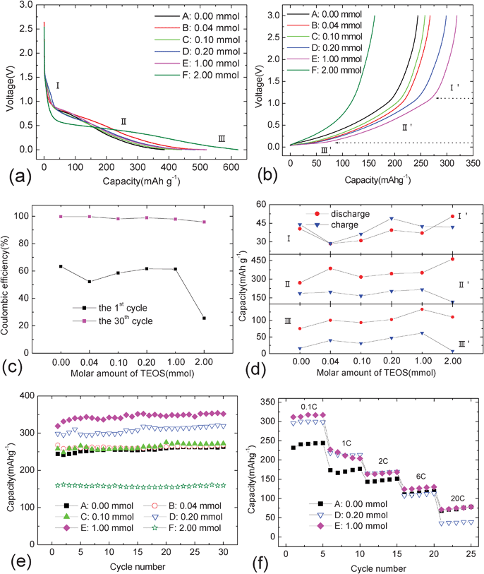 | ||
| Fig. 7 Charge-discharge curves (a, b), coulombic efficiency (c), segmented capacity (d), cycling (e) and rate (f) properties of carbon@silica composites in the voltage range between 0.0 and 3.0 V. | ||
As mentioned above, the additional capacity after silica coating mainly comes from Li-storage in the low voltage region (<0.1 V). Fig. 8a and 8b show the charge-discharge curves and corresponding cycling properties in different working voltage ranges. In previous reports it is has been shown that most Li-storage electrochemical reactions in micropores appear near or below 0.0 V.38,47 Here, a broad electrochemical window between −15 mV and 3.0 V is presented as the testing parameter for sample E. Viewed from Fig. 8a, it is obvious that a longer discharge plateau appears between −15 mV and 0.1 V. It indicates that an extra lithiation capacity of 160 mAh·g−1 can be stored in the micropores when the electrochemical window is broadened. As a result, sample E can deliver a reversible capacity of 511 mAh·g−1 after 30 cycles as shown in Fig. 8b. Therefore, carbon@silica composites with proper silica content are promising anode materials for lithium-ion batteries, which contribute to their high Li-storage property and thermal stability.
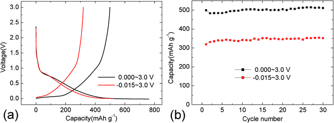 | ||
| Fig. 8 Charge-discharge curves (a) and corresponding cycling properties (b) of carbon@silica composites in different electrochemical windows. The carbon@silica composites are prepared by hydrolysis of 1.00 mmol TEOS | ||
4. Conclusions
A series of carbon@silica composites with different silica contents were prepared by a facile hydrothermal method. The surface morphology of the silica coating layer can be controlled by adjusting the amount of TEOS added. It is found that the growth process of the coating layer on carbon spheres is associated with silica nucleation and growth, spreading into a thin coating layer, then the process is repeated. By introducing this silica coating layer on the surface, the surface morphologies and graphitization degree of carbon spheres are gradually changed. As a result, the morphology and onset formation voltage of surface film formation on the surface of carbon@silica composites vary with the silica coating content. It is observed that the first irreversible reduction peak shifts negatively with the increase of silica coating content, except for the sample with the addition of 1.00 mmol TEOS. Moreover, it is also found that the existence of nano-sized silica particles on the surface is beneficial to decrease the charge transfer impedance of carbon@silica composite but smooth silica coating layer is harmful to improve charge transfer in the structure. Based on the analysis of SEM, EIS and FTIR results, it is known that all these phenomena are induced by the peculiar morphologies of carbon@silica composites with different silica coating contents. Viewed from the galvanostatic charge-discharge results, it is clear that the electrochemical behaviors of carbon@silica composites also vary with the silica coating content. It can be found that few nano-sized silica particles as a coating layer has no effect on improving the reversible charge capacity, but a continuous silica coating layer on carbon spheres can greatly enhance the electrochemical properties of carbon@silica composites. Electrochemical results show that the carbon@silica composites prepared by the addition of 1.00 mmol TEOS exhibit higher reversible capacity and better kinetic performance than those of the pristine carbon spheres. Compared with the capacity of 263 mAh·g−1 released by the pristine sample, they can deliver reversible capacities of 351 mAh·g−1 in 0.0–3.0 V and 511 mAh·g−1 in −15 mV–3.0 V after 30 cycles. This extra capacity in low voltage region, especially below 0.0 V, mainly comes from the Li-storage in micropores, which is greatly improved after silica coating.Acknowledgements
This project is sponsored by 973 Fundamental Research Program (No. 2010CB635116), National Science Foundation of China (No. 51104092), Key Project of Chinese Ministry of Education (No. 210083), Qianjiang Talent Project of Zhejiang Province (No. 2011R10089) and the Scientific Research Foundation for the Returned Overseas Chinese Scholars, State Education Ministry. The work is also supported by Hulan Excellent Doctoral Fund and K. C. Wong Magna Fund in Ningbo University.References
- Z. Y. Wang, D. Y. Luan, F. Y. C. Boey and X. W. Lou, J. Am. Chem. Soc., 2011, 133, 4738 CrossRef CAS.
- S. J. Ding, J. S. Chen, G. G. Qi, X. N. Duan, Z. Y. Wang, E. P. Giannelis, L. A. Archer and X. W. Lou, J. Am. Chem. Soc., 2011, 133, 21 CrossRef CAS.
- S. J. Ding, Z. Y. Wang, S. Madhavi and X. W. Lou, J. Mater. Chem., 2011, 21, 13860 RSC.
- S. J. Ding, D. Y. Luan, F. Y. C. Boey, J. S. Chen and X. W. Lou, Chem. Commun., 2011, 47, 7155 RSC.
- Y. J. Lee, H. Yi, W. Kim, K. Kang, D. S. Yun, M. S. Strano, G. Ceder and A. M. Belcher, Science, 2009, 324, 1051 CAS.
- K. T. Nam, R. Wartena, P. J. Yoo, F. Liau, Y. J. Lee, Y. M. Chiang, P. T. Hammond and A. M. Belcher, Proc. Natl. Acad. Sci., 2008, 107, 1 Search PubMed.
- K. T. Nam, D. W. Kim, P. J. Yoo, C. Y. Chiang, N. Meethong, P. T. Hammond, Y. M. Chang and A. M. Belcher, Science, 2006, 312, 885 CrossRef CAS.
- Y. J. Lee, D. Oh, T. Chen, G. Ceder and A. M. Belcher, Nano Lett., 2010, 10, 2433 CrossRef CAS.
- J. K. Shon, S. S. Kong, J. M. Kim, C. H. Ko, M. Jin, Y. Y. Lee, S. H. Hwang, J. A. Yoon and J. N. Kim, Chem. Commun., 2009, 6, 650 RSC.
- L. M. Huang, S. J. Wind and S. P. O'Brien, Nano Lett., 2003, 3, 299 CrossRef CAS.
- L. H. Kao and T. C. Hsu, Mater. Lett., 2008, 62, 695 CrossRef CAS.
- S. B. Yoon, J. Y. Kim, S. K. Park, J. H. Kim, M. S. Kim and J. S. Yu, Ind. Eng. Chem. Res., 2011, 50, 7998 CrossRef CAS.
- D. Y. Zhao, J. L. Feng, Q. S. Huo, N. Melosh, G. H. Fredrickson, B. F. Chmelka and G. D. Stucky, Science, 1998, 279, 548 CrossRef CAS.
- J. N. Cha, G. D. Stucky, D. E. Morse and T. J. Deming, Nature, 2000, 403, 289 CrossRef CAS.
- D. Y. Zhao, J. Y. Sun, Q. Z. Li and G. D. Stucky, Chem. Mater., 2000, 12, 275 CrossRef CAS.
- Y. K. Fan, J. M. Wang, Z. Tang, W. C. He and J. Q. Zhang, Electrochim. Acta, 2007, 52, 3870 CrossRef CAS.
- D. Arumugam and G. P. Kalaignan, J. Electroanal. Chem., 2008, 624, 197 CrossRef CAS.
- Y. D. Li, S. X. Zhao, C. W. Nan and B. H. Li, J. Alloys Compd., 2011, 509, 957 CrossRef CAS.
- H. Omanda, T. Brousse, C. Marhic and D. M. Schleich, J. Electrochem. Soc., 2004, 151, A922 CrossRef CAS.
- L. J. Fu, J. Gao, T. Zhang, Q. Cao, L. C. Yang, Y. P. Wu and R. Holze, J. Power Sources, 2007, 171, 904 CrossRef CAS.
- J. Gao, H. P. Zhang, T. Zhang, Y. P. Wu and R. Holze, Solid State Ionics, 2007, 178, 1225 CrossRef CAS.
- G. X. Wang, J. Yao, H. K. Liu, S. X. Dou and J. H. Ahn, Electrochim. Acta, 2004, 50, 517 CrossRef CAS.
- S. S. Zhang, K. Xu and T. R. Jow, Electrochem. Commun., 2003, 5, 979 CrossRef CAS.
- W. Lu, V. S. Donepudi, J. Prakash, J. Liu and K. Amine, Electrochim. Acta, 2002, 47, 1601 CrossRef CAS.
- M. Koh and T. Nakajima, Electrochim. Acta, 1999, 44, 1713 CrossRef CAS.
- H. Nozaki, K. Nagaoka, K. Hoshi, N. Ohta and M. Inagaki, J. Power Sources, 2009, 194, 486 CrossRef CAS.
- J. Shu, M. Shui, D. Xu, S. Gao, X. Li, R. L. Ren, L. Hou, J. Cui, J. J. Xu and Z. H. Zhu, J. Electroanal. Chem., 2011, 657, 187 CrossRef CAS.
- S. Shin, J. Jang, S. H. Yoon and I. Mochida, Carbon, 1997, 35, 1739 CrossRef CAS.
- D. J. Kim, H. I. Lee, J. E. Yie, S. J. Kim and J. M. Kim, Carbon, 2005, 43, 1868 CrossRef CAS.
- J. Shu, M. Shui, F. T. Huang, D. Xu and Y. L. Ren, Ionics, 2011, 17, 183 CrossRef CAS.
- Y. T. Shieh and Y. G. Lin, J. Appl. Polym. Sci., 2002, 87, 1144 CrossRef.
- J. Lambers and P. Hess, J. Appl. Phys., 2003, 94, 2937 CrossRef CAS.
- F. Hamelmann, U. Heinzmann, A. Szekeres, N. Kirov and T. Nikolova, J. Optoelectr. Adv. Mater., 2003, 7, 389 Search PubMed.
- L. X. Yi, J. Heitmann, R. Scholz and M. Zacharias, J. Phys.: Condens. Matter, 2003, 15, S2887 CrossRef CAS.
- S. Musić, N. Filipović-Vinceković and L. Sekovanić, Braz. J. Chem. Eng., 2011, 28, 89 Search PubMed.
- E. Mota-Pineda, M. Meĺendez-Lira, M. Zapata-Torres, A. Ṕerez-Centeno, M. A. Santana-Aranda and P. del Angel, Semicond. Sci. Technol., 2009, 24, 105028 CrossRef.
- R. Hofman, J. G. F. Westheim, I. Pouwel, T. Fransen and P. J. Gellings, Surf. Interface Anal., 1996, 24, 1 CrossRef CAS.
- J. Hu, H. Li and X. J. Huang, Solid State Ionics, 2007, 178, 265 CrossRef CAS.
- P. Verma, P. Maire and P. Novák, Electrochim. Acta, 2010, 55, 6332 CrossRef CAS.
- D. Aurbach, B. Markovsky, A. Shechter, Y. Ein-Eli and H. Cohen, J. Electrochem. Soc., 1996, 143, 3809 CrossRef CAS.
- J. R. Dahn, T. Zheng, Y. Liu and J. S. Xue, Science, 1995, 270, 590 CAS.
- E. Peled, V. Eshkenazi and Y. Rosenberg, J. Power Sources, 1998, 76, 153 CrossRef CAS.
- S. J. Lee, M. Nishizawa and I. Uchida, Electrochim. Acta, 1999, 44, 2379 CrossRef CAS.
- S. Komabaa, M. Watanabe, H. Groult and N. Kumagai, Carbon, 2008, 46, 1184 CrossRef.
- J. Graetz, C. C. Ahn, R. Yazami and B. Fultz, Electrochem. Solid-State Lett., 2003, 6, A194 CrossRef CAS.
- C. K. Chan, R. Ruffo, S. S. Hong and Y. Cui, J. Power Sources, 2009, 189, 1132 CrossRef CAS.
- J. Hu, H. Li and X. J. Huang, Solid State Ionics, 2005, 176, 1151 CrossRef CAS.
- Q. Wang, H. Li, L. Q. Chen and X. J. Huang, Solid State Ionics, 2002, 152–153, 43 CrossRef CAS.
- X. D. Wu, Z. X. Wang, L. Q. Chen and X. J. Huang, J. Electrochem. Soc., 2004, 151, A2189 CrossRef CAS.
| This journal is © The Royal Society of Chemistry 2012 |