High quality pristine perfluorosulfonated ionomer membranes prepared from perfluorinated sulfonyl fluoride solution†
Libin
Yang
a,
Junke
Tang
b,
Lei
Li
a,
Xiaoyong
Chen
a,
Fei
Ai
a,
Wang Zhang
Yuan
*a,
Li
Wang
b and
Yongming
Zhang
*a
aSchool of Chemistry and Chemical Engineering, Shanghai Jiaotong University, Dongchuan Road 800, Shanghai, 200240, China. E-mail: wzhyuan@sjtu.edu.cn; ymzhang@sjtu.edu.cn; Fax: +86-21-54742567; Tel: +86-21-34202613
bR&D Center of Dongyue Group, Dongyue Fluor-Silcon Material Industry Park, Zibo, Shandong, 256401, China
First published on 8th May 2012
Abstract
A new method to prepare high quality PFSI membranes from their precursor solutions is developed. The obtained membranes exhibit better dimensional stability, higher proton conductivity, and remarkably decreased methanol crossover when compared with those of traditional membranes.
Perfluorosulfonated ionomers (PFSI), with the trademark of Nafion, were first synthesized by E. I. DuPont Co. in 1962.1 In the half past century, PFSI have been extensively studied due to their unique properties, such as high ionic conductivity, excellent mechanical, chemical, and thermal stabilities.2,3 Among their variety of applications,4–6 the most promising prospect lies in proton exchange membrane fuel cells (PEMFCs),7–9 and it has become the benchmark for electrolyte membrane design in this field.10,11
Generally, pristine PFSI membranes are prepared from PFSI or its precursor, perfluorinated sulfonyl fluoride (PFSF), through melting extrusion-hydrolysis of PFSF, recast-annealing of the PFSI solution or melting extrusion of PFSI,12–14 however, little attention has been paid to PFSF solution systems. So far, works are mainly based on melting PFSF and PFSI solution systems: the melting extrusion of PFSI is only a supplementary method that is only suitable for some specific circumstances.14,15 Despite their extensive applications, membranes made from each kind of system have inherent shortages: the melting extrusion-hydrolysis membranes (MEMs) from PFSF show lower proton conduction, higher methanol crossover, and poor designability, whereas the recast-annealing membranes (RCMs) from PFSI solutions possess less chemical and thermal stability.16,17 In order to achieve high proton conductivity, good mechanical strength, excellent chemical and thermal resistance, and low gas permeability or methanol crossover are highly desirable for commercial PEMFC applications.18 Numerous methods, such as the layer-by-layer technique,19,20 sol–gel,21,22 composite,23,24 and self-assembly25 approaches have been adopted. Nevertheless, most methods only partially resolve the problems and some even bring new challenges like incorporation of unstable materials, increasing the production cost, and frequently, individual property specifications need to compromise between conflicting requirements. For instance, approaches to reduce methanol crossover always lead to the decrease of ionic conductivity because ions and methanol are transferred through the same channels.26 On the other hand, previous results have proved that the pristine PFSI membrane structure is far from a high-efficiency state,27 thus structure optimization to enhance its performance is attractive in PFSI membrane studies and applications.
Microstructure of PFSI consists of three regions, namely crystalline phase, ionic clusters, and an inhomogeneous matrix phase.2 The crystalline phase has been recognized as a necessary component that provides mechanical integrity and a barrier to solvent swelling. Evidence from prestretched recast Nafion indicates that crystallites may be considered as critical structures that impose the organization of ionic domains,28 from which the ion, gas and methanol are transferred. Therefore, ion conductivity, gas and methanol crossover resistance, mechanical strength, chemical and thermal stability might be improved through crystalline phase adjustment. This assumption is verified by our recent works, the crystallinity as well as crystallite size of PFSI membranes is increased through supercritical CO2 treatment, resulting in simultaneously improved mechanical strength, proton conductivity, and methanol crossover resistance.29,30 Now, a question of great interest has arisen: is it possible to find an approach to prepare PFSI membranes with more perfect crystallites?
It is known that crystallites result in a strong attractive interaction between the fluorinated backbones. However, extension of crystalline organization is limited by the pendant chains and the dipolar interaction between sulfonated groups.31 Decreasing sulfonate density partially releases the strong interactions, however, it inevitably reduces the proton conductivity. Nevertheless, the dipolar interactions can be reduced if the ionic sulfonates could be changed into other forms. Alternatively, the precursor, unhydrolyzed PFSF may become a promising candidate for preparing high quality PFSI membranes. However, PFSF cannot be dissolved in common solvents, rendering melt processing the only choice for it in the past.32–34 Compared to PFSI solution systems, membranes prepared from melting PFSF normally show smaller crystalline size due to the high viscosity and short crystallization time, making many properties not as good as those of RCMs.16,17
In this work, it is found that PFSF can be dissolved in such fluorocarbon solvents as hexafluoropropene trimer (HFPT), perfluorotributylamine, tetrafluoroethylene oligomers, and perfluoro[2-(2-fluorosulfonylethoxy) propyl] vinyl ether at elevated temperatures. Unlike PFSI solution, the PFSF solution is a totally hydrophobic system, which is useful in some cases like for PFSI–PTFE composite membrane preparation, where the difficulty to impregnate a hydrophilic PFSI solution into the porous hydrophobic PTFE matrix35,36 is perfectly resolved. Similar to PFSI solutions,37,38 PFSF aggregates in fluorocarbon solvents, and the aggregate size is increased with decreasing ion exchange capacity (IEC) (ESI†). Detailed information about the aggregation structure is still unclear, and it will not be discussed herein. Because the knowledge of solution properties is a prerequisite to understand the membrane formation process and performance, numerous works have been carried out on PFSI solutions.37–39 The discovery of PFSF solutions may open a new approach for PFSI study.
Membranes based on the PFSF solution were successfully prepared. Unlike the recast-annealing of the PFSI solution method, annealing at a temperature higher than 120 °C is not indispensable herein. And the properties of the membranes treated at 160 (P160) and 80 °C (P80) are compared with those prepared in traditional ways. The basic properties of the membranes are shown in Fig. 1. Clearly, compared to MEMs and RCMs, P160 and P80 exhibit better dimensional stability, higher proton conductivity, and remarkably decreased methanol crossover (one third of MEMs and 60% of RCMs). Meanwhile, the low solubility of P80 (4.87%) in solvent demonstrates that the high temperature annealing process is not indispensable in this method even though it exerts a positive effect on membrane properties. This may meet the requirement in specific cases that high temperature should be avoided. The lower solubility of MEMs (3.27%) than those of P160 (4.30%) and P80 (4.87%) should be ascribed to its great thickness (95 μm) rather than crystallinity. With similar thickness (∼25 μm), the solubility of the RCM (9.01%) is nearly twice of those for new membranes. Moreover, as a new method based on a solution system, the excellent designability makes it compatible with traditional modification techniques to further improve the membrane properties.
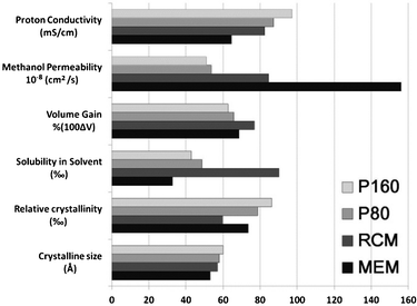 | ||
| Fig. 1 Basic properties of the membranes prepared by different methods. The membrane thickness is 24, 23, 25, 95 μm for P160, P80, RCM and MEM, respectively. | ||
The relative crystallinity and crystalline size data in Fig. 1 were obtained through X-ray diffraction (XRD) analysis in a synchrotron radiation facility. As shown in Fig. 2, a crystalline peak centred at 14.1° and two amorphous peaks located at 12.7° and 31.6° are observed. The crystallinity and crystalline size are calculated40,41 and summarized in Table S1 (ESI†). Apparently, both of them increased when the PFSF solution casting method is adopted, and higher treatment temperature positively impacts on the crystallite formation. It is reasonable that the decreased dipole–dipole interactions in PFSF as well as elevated temperature remarkably promote its chain mobility and molecular packing, thus resulting in higher crystallinity and bigger crystalline size. Such changes give rise to the improvement of membrane properties, including dimensional stability, methanol crossover and solubility.
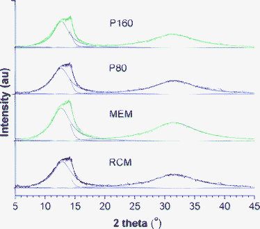 | ||
| Fig. 2 XRD spectra of varying dry PFSI membranes prepared by different methods. The peak centred at 14.1° is ascribed to the crystalline phase and two amorphous peaks are located at 12.7° and 31.6°. | ||
PFSI chain movement is restricted by dipolar interaction between sulfonated groups, which is reflected by its glass transition temperatures (Tg), as deduced from the dynamic mechanical analysis (DMA) results (ESI†). The Tg values for PFSF and PFSI are 20 and 120 °C, respectively. The low Tg endows PFSF active chain segment movement even at ambient temperature. Therefore, PFSF solution generated membranes at relatively low temperature (>20 °C) could obtained with a similar inner crystalline structure to that of PFSI solution derived membranes annealed at high temperature (>120 °C), making the high temperature annealing (>120 °C) procedure not indispensable. Moreover, proton conductivity of PFSI membranes is increased as annealing temperature increases,17,41,42 which means higher chain mobility tends to afford membranes with higher proton conductivity; considering the remarkable difference in Tg between PFSF and PFSI, the proton conductivity order of varying membranes presented herein is thus reasonable.
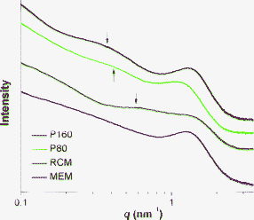
Membrane morphology was also studied by small angle X-ray scattering (SAXS). It is well known that the SAXS graphs of PFSI membranes generally exist in two types of scattering maxima of different origins: (1) the matrix knee at the q value of ∼0.6 nm−1 corresponds to the interference between crystalline structures, and (2) the peak at the q value of 1.1∼1.9 nm−1 can be assigned to the ionic clusters.40,43,44 As depicted in Fig. 3, the matrix knee is only observed for solution made membranes, revealing a particularly strong preparation method effect on the membrane structure. For PFSF solution generated membranes, especially for P160, the crystalline order is improved and the repetition distance is also increased as the peak intensity increases and the peak position shifts toward much smaller q values.
The membrane inner structure is also demonstrated by thermal gravimetric analysis (TGA). As shown in Fig. 4, PFSI membranes display a gradual loss of approximately 4% below 270 °C, which can be attributed to the loss of water. Above 270 °C, PFSI begins to decompose and three stages are clearly observed. The first stage (270∼390 °C) should be ascribed to the desulfonation process because the unhydrolyzed PFSF membrane shows no weight loss in this stage, while the second (390∼470 °C) and third stages (470∼570 °C) may be related to the decomposition of the side-chain and PTFE backbone, respectively. These results are quite similar to previously reported works.45,46 Despite the initial decomposition temperatures for all membranes being equal, the derivative weight loss curves in Fig. 4 reveal that the maximum rates of desulfonation and side-chain decomposition occur at ca. 328, 338, 340, 358 °C and 441, 438, 414, 436 °C for P160, P80, RCM and MEM, respectively. The results are in accordance with the order of ionic conductivity and crystallinity, suggesting that the side chains located in semicrystalline matrix are protected by crystallites during thermal decomposition. While most sulfonic acid groups are located in ionic clusters, some are unavoidably embedded in the matrix. Higher ionic conductivity means fewer sulfonic acid groups are embedded in matrix, thus making the desulfonation process much easier than those with lower ionic conductivity. The high thermal stability of PFSF (up to 380 °C) makes its solutions very attractive in applications like PTFE involved electrode preparation in PEMFC (PTFE needs to be treated at 300∼350 °C15).
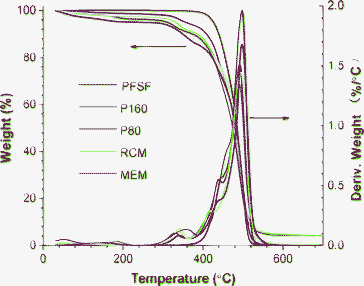 | ||
| Fig. 4 TGA thermograms of PFSF and PFSI membranes. PFSF is a melting extruded PFSF membrane before being hydrolyzed. Three peaks from 300 to 600 °C in deriv. weight profile are ascribed to the decomposition of sulfonic acid groups, side-chain and PTFE backbone, respectively. | ||
Chemical stability of the membranes is particularly important for their PEMFC applications. Good chemical stability is favoured for long durability of the membranes. Herein, a Fenton reaction experiment47,48 (ESI†) was conducted to test the chemical stability of varying membranes. Because the free radicals generated from the Fenton reagent will initially attack the membrane surface, the crystalline part with greater chemical stability will form a barrier to protect the weaker part from attacking. Therefore membranes of higher crystallinity would be more stable in chemical corrosion and it is proven by the results shown in Fig. 5. Clearly, after 60 h Fenton experiment, many bubbles emerged for RCMs and MEMs, and smooth surfaces are observed for P80 and P160, thus testifying the excellent chemical stability of the PFSF solution-cast membranes.
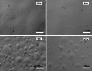 | ||
| Fig. 5 SEM photographs of varying PFSI membranes after 60 h Fenton experiment. | ||
Conclusions
In summary, a new solution casting method for preparing high quality pristine PFSI membranes from PFSF solution is explored. The obtained membranes exhibit higher ionic conductivity, better methanol crossover resistance and remarkably enhanced chemical stability than those prepared in traditional ways, making the membranes promising candidates for fuel cell applications. Considering almost all previous works are based on PFSI solutions, PFSF or PFSI melts, both in fundamental and technical aspects, the discovery of PFSF solutions offers a new system for PFSI study. Related work is under active research in our group and the results will be reported in due course.Acknowledgements
The authors thank Shanghai Synchrotron Radiation Facility for the XRD test. This project was financially supported by the Technologies R&D Program of China (2011BAE08B00), the National Natural Science Foundations of China (201104044) and the Shanghai Leading Academic Discipline Project (B202). W.Z.Y thanks the Start-up Foundation for New Faculties of Shanghai Jiao Tong University.References
- C. Heitner-Wirguin, J. Membr. Sci., 1996, 120, 1–33 CrossRef CAS.
- K. A. Mauritz and R. B. Moore, Chem. Rev., 2004, 104, 4535–4586 CrossRef CAS.
- S. Bose, T. Kuila, T. X. H. Nguyen, N. H. Kim, K.-t. Lau and J. H. Lee, Prog. Polym. Sci., 2011, 36, 813–843 CrossRef CAS.
- I. Yamanaka and T. Murayama, Angew. Chem., Int. Ed., 2008, 47, 1900–1902 CrossRef CAS.
- L. Feng, Y. Chen, J. Ren and X. Qu, Biomaterials, 2011, 32, 2930–2937 CrossRef CAS.
- C. Luo, X. Zuo, L. Wang, E. Wang, S. Song, J. Wang, J. Wang, C. Fan and Y. Cao, Nano Lett., 2008, 8, 4454–4458 CrossRef CAS.
- R. Devanathan, Energy Environ. Sci., 2008, 1, 101–119 CAS.
- M. Michel, A. Taylor, R. Sekol, P. Podsiadlo, P. Ho, N. Kotov and L. Thompson, Adv. Mater., 2007, 19, 3859–3864 CrossRef CAS.
- Y. Paik, S.-S. Kim and O. H. Han, Angew. Chem., Int. Ed., 2007, 47, 94–96 CrossRef.
- O. Diat and G. Gebel, Nat. Mater., 2008, 7, 13–14 CrossRef CAS.
- B. Dong, L. Gwee, D. Salas-de la Cruz, K. I. Winey and Y. A. Elabd, Nano Lett., 2010, 10, 3785–3790 CrossRef CAS.
- D. E. Curtin, R. D. Lousenberg, T. J. Henry, P. C. Tangeman and M. E. Tisack, J. Power Sources, 2004, 131, 41–48 CrossRef CAS.
- R. B. Moore and C. R. Martin, Macromolecules, 1988, 21, 1334–1339 CrossRef CAS.
- R. B. Moore, K. M. Cable and T. L. Croley, J. Membr. Sci., 1992, 75, 7–14 CrossRef CAS.
- S. S. Kocha, in Handbook of Fuel Cells, John Wiley & Sons, Ltd, 2010 Search PubMed.
- R. F. Silva, M. De Francesco and A. Pozio, Electrochim. Acta, 2004, 49, 3211–3219 CrossRef CAS.
- Y. Luan, Y. Zhang, H. Zhang, L. Li, H. Li and Y. Liu, J. Appl. Polym. Sci., 2008, 107, 396–402 CrossRef CAS.
- B. C. H. Steele and A. Heinzel, Nature, 2001, 414, 345–352 CrossRef CAS.
- T. R. Farhat and P. T. Hammond, Adv. Funct. Mater., 2006, 16, 433–444 CrossRef CAS.
- M. Yang, S. Lu, J. Lu, S. Jiang and Y. Xiang, Chem. Commun., 2010, 46, 1434–1436 RSC.
- M. Amjadi, S. Rowshanzamir, S. J. Peighambardoust, M. G. Hosseini and M. H. Eikani, Int. J. Hydrogen Energy, 2010, 35, 9252–9260 CrossRef CAS.
- K. Valle, P. Belleville, F. Pereira and C. Sanchez, Nat. Mater., 2006, 5, 107–111 CrossRef CAS.
- W. Han and K. Lun Yeung, Chem. Commun., 2011, 47, 8085–8087 RSC.
- Z. Chai, C. Wang, H. Zhang, C. M. Doherty, B. P. Ladewig, A. J. Hill and H. Wang, Adv. Funct. Mater., 2010, 20, 4394–4399 CrossRef CAS.
- J. Lu, S. Lu and S. P. Jiang, Chem. Commun., 2011, 47, 3216–3218 RSC.
- B. P. Ladewig, R. B. Knott, A. J. Hill, J. D. Riches, J. W. White, D. J. Martin, J. C. Diniz da Costa and G. Q. Lu, Chem. Mater., 2007, 19, 2372–2381 CrossRef CAS.
- D. A. Bussian, J. R. O'Dea, H. Metiu and S. K. Buratto, Nano Lett., 2007, 7, 227–232 CrossRef CAS.
- J. Lin, P.-H. Wu, R. Wycisk, P. N. Pintauro and Z. Shi, Macromolecules, 2008, 41, 4284–4289 CrossRef CAS.
- L. Su, L. Li, H. Li, Y. Zhang, W. Yu and C. Zhou, J. Membr. Sci., 2009, 335, 118–125 CrossRef CAS.
- Z. Cai, L. Li, L. Su and Y. Zhang, Electrochem. Commun., 2012, 14, 9–12 CrossRef CAS.
- L. Rubatat and O. Diat, Macromolecules, 2007, 40, 9455–9462 CrossRef CAS.
- L. Li, F. Shang, L. Wang, S. Pei and Y. Zhang, Energy Environ. Sci., 2010, 3, 114–116 CAS.
- S.-Y. Ahn, Y.-C. Lee, H. Y. Ha, S.-A. Hong and I.-H. Oh, Electrochim. Acta, 2004, 50, 571–575 CrossRef CAS.
- N. P. Cele, S. S. Ray, S. K. Pillai, M. Ndwandwe, S. Nonjola, L. Sikhwivhilu and M. K. Mathe, Fuel Cells, 2010, 10, 64–71 CAS.
- H. Tang, M. Pan, S. P. Jiang, X. Wang and Y. Ruan, Electrochim. Acta, 2007, 52, 5304–5311 CrossRef CAS.
- K. M. Nouel and P. S. Fedkiw, Electrochim. Acta, 1998, 43, 2381–2387 CrossRef CAS.
- P. A. Cirkel, T. Okada and S. Kinugasa, Macromolecules, 1998, 32, 531–533 CrossRef.
- M. Takasaki, K. Kimura, K. Kawaguchi, A. Abe and G. Katagiri, Macromolecules, 2005, 38, 6031–6037 CrossRef CAS.
- B. Loppinet, G. Gebel and C. E. Williams, J. Phys. Chem. B, 1997, 101, 1884–1892 CrossRef CAS.
- M. Fujimura, T. Hashimoto and H. Kawai, Macromolecules, 1981, 14, 1309–1315 CrossRef CAS.
- J. E. Hensley, J. D. Way, S. F. Dec and K. D. Abney, J. Membr. Sci., 2007, 298, 190–201 CrossRef CAS.
- O. Kwon, S. Wu and D.-M. Zhu, J. Phys. Chem. B, 2010, 114, 14989–14994 CrossRef CAS.
- G. Gebel, P. Aldebert and M. Pineri, Macromolecules, 1987, 20, 1425–1428 CrossRef CAS.
- K. Schmidt-Rohr and Q. Chen, Nat Mater, 2008, 7, 75–83 CrossRef CAS.
- L. Sun and J. S. Thrasher, Polym. Degrad. Stab., 2005, 89, 43–49 CrossRef CAS.
- D. L. Feldheim, D. R. Lawson and C. R. Martin, J. Polym. Sci., Part B: Polym. Phys., 1993, 31, 953–957 CrossRef CAS.
- J. Healy, C. Hayden, T. Xie, K. Olson, R. Waldo, M. Brundage, H. Gasteiger and J. Abbott, Fuel Cells, 2005, 5, 302–308 CrossRef CAS.
- T. Sugawara, N. Kawashima and T. N. Murakami, J. Power Sources, 2011, 196, 2615–2620 CrossRef CAS.
Footnote |
| † Electronic Supplementary Information (ESI) available: See DOI: 10.1039/c2ra20318a/ |
| This journal is © The Royal Society of Chemistry 2012 |

