Magnetite modified graphene nanosheets with improved rate performance and cyclic stability for Li ion battery anodes†
Jiantao
Zai
,
Chao
Yu
,
Qiong
Zou
,
Liqi
Tao
,
Kaixue
Wang
,
Qianyan
Han
,
Bo
Li
,
Yinglin
Xiao
,
Xuefeng
Qian
and
Rongrong
Qi
*
School of Chemistry and Chemical Technology, State Key Laboratory of Metal Matrix Composites, Shanghai Jiao Tong University, Shanghai, 200240, P. R. China. E-mail: rrqi@sjtu.edu.cn; Fax: (+86) 21-5474-1297; Tel: (+86) 21-5474-7806
First published on 29th March 2012
Abstract
Magnetite modified graphene nanosheets (MGNSs) were synthesized through a simple ultrasonic method, electrochemical performances indicated that the obtained MGNSs exhibited remarkably high reversible lithium storage capacity (1235 mAh g−1 after 50 cycles at 0.2 A g−1), good rate capability (315 mAh g−1 at 10 A g−1) and improved cycling stability (450 mAh g−1 after nearly 700 cycles at 5 A g−1). The improved electrochemical performances of the obtained MGNSs could be attributed to its inherent electronic conductivity, excellent mechanical properties and expanded (002) interlayer spacing of GNSs. Furthermore, magnetite nanoparticles anchored onto graphene nanosheets (GNSs) could serve as spacers to reduce the stack/restack of GNSs during charge-discharge process and improve their electrochemical performances as anode materials for lithium-ion batteries (LIBs).
Introduction
In the past few years, Li-ion batteries have been demonstrated as one of the most important power sources for electric bicycles, electric/hybrid vehicles and power tools due to their high energy density, high voltage and long lifespan. Although Li-ion batteries have been widely utilized as power sources for mobile electronics, they are still objects of intense researches and developmental activities.1–7 Significant interest has been focused on the development of new electrode materials with higher capacities, lower costs, environmental friendliness and increased safety compliance.3–12 Up to now, graphite is the most popular anode material in today's commercial rechargeable Li-ion batteries due to its good electron conductivity, fast lithium insertion and extraction kinetics, high thermal and chemical stability and low cost.13–15 However, the relatively low storage capacity and poor rate performance restrict its applications in rechargeable Li-ion batteries with high energy and power densities. Recently, GNSs have attracted special attention for their high surface area, unparalleled thermal and electronic conductivity, excellent mechanical properties, unprecedented impermeability, plus fascinating electronic properties,16–22 and have also been studied for Li-ion storage to meet the requirements for future energy storage systems.23,24 Previous works revealed that the graphene anode materials had large initial discharge capacity (600–2042 mAh g−1) and reversible capacity (540–1264 mAh g−1). However, they still suffer from fast capacity fading because of the restack of GNSs during charge-discharge process.25–27 To surmount this problem, the restacking of GNS must be reduced, which will improve the cyclic performance of GNSs.For its convenient synthetic method, high capacity, eco-friendliness, natural abundance and high electronic conductivity, magnetite is considered an anode material for next generation lithium ion batteries (LIBs).28–31 It was revealed that metal oxide/graphene composites, in which the content of GNS was usually less than 50 wt%, possessed high reversible capacity.32–39 Despite this, their rate performance still needs to be improved because a larger amount of metal oxide will decrease the conductivity of metal oxide/graphene composites. Thus both the reversible capacity and rate capability of composites would be improved if more GNS was added into the Fe3O4/graphene composites.
Herein, MGNSs with high content of GNS (89%) were prepared via reducing graphene oxide (GO) and FeCl3 in a pretreated GO/FeCl3 hydrogel system by hydrazine through a ultrasonic irradiation process. The as-obtained MGNSs exhibited discharge and charge capacities of 1976 mAh g−1 and 1178 mAh g−1, respectively good cycling performance and rate capability. The synthetic method presents a promising route for the scale up of GNS-based anodes for Li-ion batteries.
Experiment
Preparation of MGNSs
Graphene oxide (GO) was first synthesized by the modified Hummers method.40 In a typical process for preparing MGNSs, 0.20 g of FeCl3·6H2O and 0.9 g of GO were added into 10 ml H2O. The mixture was stirred for 30 min and treated by ultrasonication for 1 h to allow its transformation to a uniform hydrogel. After that, 10 ml hydrazine hydrate was added into the system, followed by further ultrasonic treatment for 30 min. The products were collected by vacuum filtration, washed with distilled water and dried in vacuum at 60 °C for overnight. Pure GNS was also prepared by the similar procedure with the absence of FeCl3·6H2O.Characterization
The morphology and structure of the obtained products were characterized by X-Ray Diffraction (XRD, Shimadzu XRD-6000, Cu-Kα, 40 kV, 30 mA), Field emission scanning electron microscopy (FESEM, FEI SIRION 200) and Transmission Electron Microscope (TEM, JEOL, JEM-2100). Thermogravimetric analysis (TGA) was carried out on a Perkin-Elmer 7 instrument to determine the weight ratio of GNS to Fe3O4. Raman spectra were recorded on a Super LabRam-II spectrometer with a holographic grating of 1800 g mm−1. X-ray photoelectron spectroscopy (XPS, Versa Probe PHI-5000, ULVAC-PHI Inc., Osaka, Japan) were used to probe the composition. Nitrogen adsorption-desorption measurement were conducted at 77.7 K on a Micromeritics ASAP 2010 analyzer. The pore volume and specific surface area of products were estimated by the Barett–Joyner–Halenda (BJH) with Brunauer–Emmett–Teller (BET) analyses, respectively.Electrochemical measurement
Electrochemical measurements were carried out using homemade coin-type half cells (2016 type) with lithium metal as the counter and reference electrodes at room temperature. The working electrode was fabricated by mixing MGNSs, acetylene black and polyvinylidene fluoride binder in the weight ratio of 8![[thin space (1/6-em)]](https://www.rsc.org/images/entities/char_2009.gif) :
:![[thin space (1/6-em)]](https://www.rsc.org/images/entities/char_2009.gif) 1
1![[thin space (1/6-em)]](https://www.rsc.org/images/entities/char_2009.gif) :
:![[thin space (1/6-em)]](https://www.rsc.org/images/entities/char_2009.gif) 1. The cells were assembled in an Ar-filled glove box, with Li foil as the reference and counter electrodes, 1M solution of LiClO4 in ethylene carbonate (EC)/diethylene carbonate (DEC) (1
1. The cells were assembled in an Ar-filled glove box, with Li foil as the reference and counter electrodes, 1M solution of LiClO4 in ethylene carbonate (EC)/diethylene carbonate (DEC) (1![[thin space (1/6-em)]](https://www.rsc.org/images/entities/char_2009.gif) :
:![[thin space (1/6-em)]](https://www.rsc.org/images/entities/char_2009.gif) 1 vol%) as electrolyte, and polyethylene film (Celgard 2300) as the separator. Galvanostatic charge and discharge measurements were controlled between 1 mV and 3 V under designated current density on a LAND CT2001 A cell test instrument (Wuhan Kingnuo Electronic Co, China) at 25 °C. Cyclic voltammetry (CV) was carried out in the potential range of 0.0–3 V (vs. Li+/Li) with a scan rate of 0.1 mV s−1, using a CHI660C Electrochemical Workstation (Shanghai. Chenhua Instrument Co. Ltd).
1 vol%) as electrolyte, and polyethylene film (Celgard 2300) as the separator. Galvanostatic charge and discharge measurements were controlled between 1 mV and 3 V under designated current density on a LAND CT2001 A cell test instrument (Wuhan Kingnuo Electronic Co, China) at 25 °C. Cyclic voltammetry (CV) was carried out in the potential range of 0.0–3 V (vs. Li+/Li) with a scan rate of 0.1 mV s−1, using a CHI660C Electrochemical Workstation (Shanghai. Chenhua Instrument Co. Ltd).
Results and discussion
Scheme 1 shows the preparation and electrochemical cyclic performance of MGNSs as an anode in RLBs. Pre-synthesized GO is first dispersed into DI water and treated by ultrasonication to allow its transformation to a uniform hydrogel. Then FeCl3·6H2O is added into the gel, and Fe3+ cations will adsorbed onto GO under the strong ultrasonic treatment because GO is highly negatively charged due to the ionization of carboxylic acid and phenolic hydroxyl groups.19 Thirdly, GO and some Fe3+ cations will be reduced to GNSs and Fe2+ cations, and to form MGNSs in situ when hydrazine hydrate is added. Finally, the MGNSs are obtained by vacuum filtration and drying. The obtained MGNSs are carefully characterized and assembled into RLBs.It is noted that the amount of FeCl3·6H2O plays a key effect on the phase formation of magnetite because the reducibility of hydrazine hydrate is sensitive to the pH value of reaction system. Amixture of FeO and Fe is only obtained if 0.05 g (Fig. S1, ESI†) or 0.1 g FeCl3·6H2O (Fig. S2†) is used. Pure magnetite will be obtained when 0.2 g FeCl3·6H2O is used (Fig. 1a). However, more FeCl3·6H2O (0.4 g, Fig. S3†) will lead to lower crystallinity of product. And only FeOOH is obtained when 0.9 g FeCl3·6H2O is used (Fig. S4†). Thus 0.2 g FeCl3·6H2O is used to prepare MGNSs and to assemble RLBs in the following process.
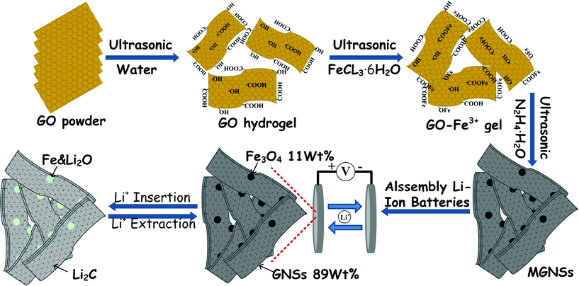 | ||
| Scheme 1 Preparation scheme and electrochemical cyclic performance of MGNSs as anodes in RLBs | ||
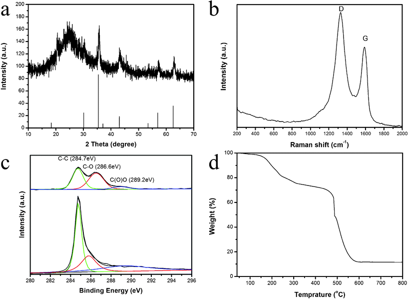 | ||
| Fig. 1 XRD pattern (a), Raman spectrum (b), XPS C 1s spectra (c) and TGA pattern (d) of MGNSs. | ||
The typical X-ray diffraction (XRD) pattern of the final product (up) together with the standard Fe3O4 (down, JCPDS No. 74-0748) is shown in Fig. 1a. Besides the diffraction peaks of Fe3O4, an additional broad (002) diffraction peak centered at 24.6° (d = 4.2 Å) can be attributed to GNS.41
In general, the D peak corresponds with the k-point phonons of A1g symmetry, while the G peak is related to the E2g phonons of Csp2 atoms.42,43 The information about the ordered and/or disordered crystal structure of GNSs can be acquired from the characteristic peaks in the Raman spectrum. From Fig. 1b, one can see that a broad D band (1330 cm−1, disorder-induced phonon mode) and a broad G band (1610 cm−1, graphite band) is observed in the product, and the D/G intensity ratio (ID/IG) is of 1.17, which is consistent with the data of GNSs in previous reports20,25. The data imply that the extensive oxidation and sonication could lead to a decrease in the size of the in-plane sp2 domains, as well as an increase in the edge planes and disorder of the as-prepared GNSs. On the other hand, the modification of magnetite would also increase the disordered degree of GNSs. As shown in the C1s scans of the XPS spectra (Fig. 1c), the peaks located at 284.7 eV can be attributed to the characteristic peak of C1s (C–C); the peaks at 286.6 eV are assigned to hydrocarbons and their oxidative forms (e.g., C–OH and C–O–C), and the peaks at 289.2 eV associate with carbonate ions.33,41 Compared with the spectrum of GO, one can see that the intensity of the characteristic peak of C1s is much higher than that of C–O chemical bonds in the spectrum of MGNSs, indicating the formation of graphene after sonochemical process. To confirm the presence of Fe3O4, an Fe 2p scan of the XPS spectrum is performed (Fig S5†). The peaks located at 724.7 eV and 711.2 eV correspond to Fe 2p1/2 and 2p2/3 of Fe3O4.44,45 TGA result indicates that the amount of Fe3O4 in the MGNSs is about 11.6%.
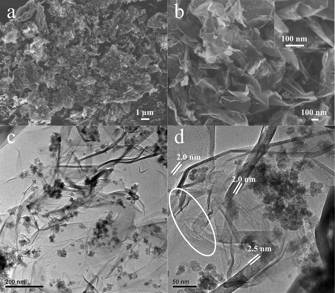
FESEM and TEM images of MGNSs are shown in Fig. 2. Fig. 2a shows that the obtained products are in agglomeration with a porous structure, which is very different to the conventional crumpled paper-like structure of GNSs.25,40,42,43 The higher magnification FESEM image (Fig. 2b) clearly shows the naturally crumpled and curved structure of GNSs with a very thin thickness and the Fe3O4 nanoparticles are anchored on/into curved GNSs (Fig. 2b insert). From the TEM images (Fig. 2c–d), one can clearly find that Fe3O4 nanoparticles of about 20 nm disperse into/on GNSs. On the other hand, the GNSs are scrolled and entangled with each other, and some tube-like GNSs exist in the scrolled GNSs because of the corrugation and scrolling of GNSs resulting from the thermodynamically stable 2D membrane structure via bending.42
The nitrogen adsorption–desorption isotherms and corresponding pore size distribution of MGNSs are shown in Fig. 3. The Brunauer–Emmett–Teller (BET) specific surface area of MGNSs is about 97.7 m2 g−1, and type IV with an H3 type hysteresis loop of the nitrogen adsorption/desorption isotherm suggests that the obtained MGNSs have slit-like pores, consistent with the above microscopy observations. The average pore diameter is about 12.6 nm, calculated by the BJH method from the desorption isotherm. Pore-size distribution also indicates that the obtained MGNSs have a large number of 3.6 nm pores. These hierarchically porous structures existing in the obtained MGNSs would serve as the path of lithium transition and further improve their rate performance.
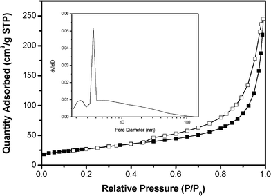 | ||
| Fig. 3 Nitrogen adsorption and desorption isotherms of magnetite modified GNS at 77 K with a corresponding pore-size distribution (inset) calculated by the BJH method from the desorption isotherm. | ||
The capacity and cycle performance of the obtained MGNSs based electrodes were measured by galvanostatic charge–discharge measurement at a current density of 0.2 A g−1 with a potential window from 1 mV to 3 V (versus Li/Li+). From Fig. 4a, we can see that the obtained MGNSs deliver a large specific capacity of about 1976 mAh g−1 and a reversible capacity of 1178 mAh g−1 at the 1th cycle. The large irreversible capacity of ∼800 mAh g−1 is associated with the solid electrolyte interphase (SEI) on the surface of GNSs and the reaction of oxygen-containing functional groups on graphene with lithium ions.26,32,46,47 Since the 2nd cycle, the electrode performs a similar discharge–charge process, indicating its good cyclic stability with a reversible capacity of ∼1200 mAh g−1. From Fig. 4a, we can also see that the mild discharge slopes between 0.83 and 0.93V have a reversible capacity of nearly 100 mAh g−1, which is contributed by magnetite (corresponding to the magnetite contents by weight in the MGNSs of 11.6% and the theoretical capacity of magnetite of 922 mAh g−135). The other reversible capacities are derived from the lithium storage in the GNSs. Based on the previous reports, the lithium storage in GNSs can be divided into two parts: the capacity above 0.5 V vs. Li/Li+ may be due to lithium storage onto the graphene surface or on the edge plane; below 0.5 V should be attributed to lithium intercalation into the graphene layers.47–49
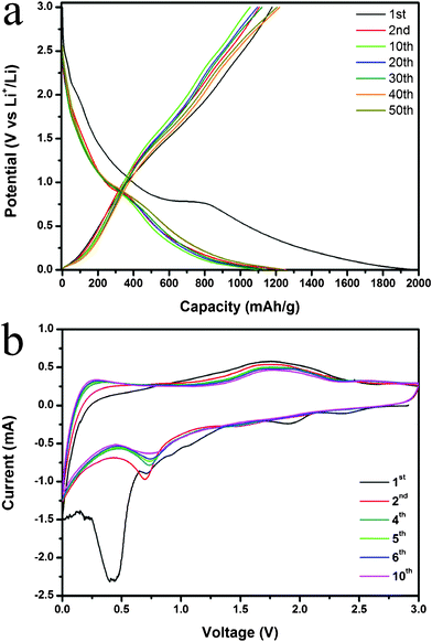 | ||
| Fig. 4 Lithium storage properties of MGNSs: the galvanostatic voltage profiles between 0.001 V and 3.0 V for the 1st, 2nd, 10th, 30th and 50th cycle (a), Cyclic voltammograms between 0.0 V and 3.0 V at a scan rate of 0.5 mVs−1 (b). | ||
Cyclic voltammogram (CV) experiments were further conducted to evaluate the electrochemical performances of MGNSs based electrodes at a scan rate of 0.5 mV s−1 over the voltage range of 0.0–3.0V (Fig. 4b). Several small cathodic (reduction) peaks above 1.0V and a broad large cathodic peak centered at 0.45V are observed in the 1st cycle, and then disappear since the 2nd cycle, which can be associated with the formation of the SEI film and the reactions between oxygen-containing functional groups on graphene with lithium ions and co-intercalation of solvated lithium ions.48–52 The relatively smaller peaks at 0.7 V in the cathodic process and the broad peaks centered at 1.7 V in the anodic process should be attributed to the Faradic capacitance both on the surface and the edge sites of GNSs,48,52–54 and the conversion reaction35 of magnetite nanoparticles with lithium ions also have a contribution to this cathodic peak.32,34,35,37. The reversible peaks located at 0–0.3 V can be associated with lithium intercalation into the graphene layers, and absorbed on both sides of GNSs.32,46,53 On the other hand, no obvious change of CV curves since the 2nd circle implies that the electrode is stable after the first cycle.
As shown in the cyclic performances of all electrodes at a current density of 0.2 A g−1 (Fig. 5a), MGNSs deliver a high discharge capacity of 1230 mAh g−1 in the 2nd cycle, which is larger than the theoretical value of GNSs (744 mAh g−1, when lithium is stored on both sides of graphene sheet by creating LiC3 structures).55 Previous works indicated that the reversible capacities can increase with expansion in the (002) interlayer spacing of GNSs based on the Li2 covalent molecule model, which would predict a high Li storage capacity of 1116 mAh g−1 when the interlayer spacing is large enough (∼4.0 Å).25,42,43,47 In this work, the (002) interlayer spacing of graphene in MGNSs is 4.2 Å, which would also lead to a higher Li storage capacity of 1230 mAh g−1. On the other hand, the hierarchically porous structure of the obtained MGNSs can also store lithium and further enhance the reversible capacity.56–58 The reversible capacities of MGNSs are about 1100 mAh g−1 at the initial 20 cycles, and increase to nearly 1200 mAh g−1 in the following cycles, and maintain a capacity of 1243 mAh g−1 at the 50th cycle because of the gradual activation process.59 Compared to that of MGNSs, GNSs shows a much worse capacity of about 500 mAh g−1 in the initial 10 cycles and gradually decreases to 405 mAh g−1 at the 50th cycle, and the products prepared with different amounts of FeCl3·6H2O also have a much worse capacity of below 500 mAh g−1 (Fig. S5, ESI†). The discharge–charge cycling behaviors indicate MGNSs have a much larger reversible capacity and better cyclic stability than that of pure GNSs.
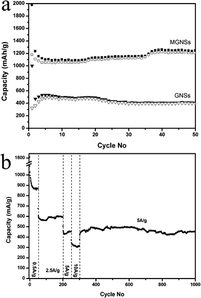 | ||
| Fig. 5 Lithium storage properties of MGNSs: the cyclic behaviors at 0.2 A g−1 and an electrode based on pure GNS is used as a comparison (a) and rate performance and long term cyclic stability (b). | ||
Because the good electronic conductivity of GNSs can decrease the Ohmic loss and further provide an electronic conduction pathway, MGNSs would have good rate capabilities.
From Fig. 5b, one can see that the obtained MGNSs keep a reversible capacity of 860, 590, 450 and 315 mAh g−1 at current densities of 0.5, 2.5, 5 and 10 A g−1, respectively. These results indicate that the as-synthesized MGNSs show a superior rate capability, which is higher than those of most carbonous anode materials, such as GNSs, nitrogen-doped GNSs (250 mAh g−1 at 2.1 A g−1), carbon nanofibers (CNF) grown on GNSs, carbon nanocages (235 mAh g−1 at 2.0 A g−1), carbon nanotubes (CNT), CNF/natural graphite.48,60,61 The high rate capability of the obtained MGNSs also matches well with that of multiwall carbon nanotubes grown on copper (∼900 mAh g−1 at 0.37 A g−1, 767 mAh g−1 at 1.116 A g−1), in which it is believed that the multiwall carbon nanotube based electrode has the highest capacity compared to other anodes fabricated by carbon nano/meso-structures, along with its composites at all the current rates.49 Moreover, the electrode based on MGNS recovers its capacity or even a bit higher when the current density returns to 5 A g−1, and highly stable capacities of nearly 500 mAh g−1 can be maintained after several hundred cycles at such a high current density. The capacity of 450 mAh g−1 is still kept at a rate of 5 A g−1 after 1000 cycles' discharge–charge process, indicating that the electrode has good stability.
The above results indicate that the obtained MGNSs have a highly reversible capacity, excellent cyclic performance and superior rate capabilities. The enhanced lithium storage performance can be assigned to the following reasons (Scheme 1). Firstly, the previous reports indicated that the capacity of GNS increased with the expansion in (002) interlayer spacing and a Li storage capacity of 1116 mAh g−1 (LiC2) would be maintained when the interlayer spacing was about 4.0 Å according to the Li2 covalent molecule model.25,42,43,47 Thus a higher lithium storage capacity of GNS (> 1116 mAh g−1) could be expected because the interlayer spacing of GNS in the obtained MGNSs is about 4.2 Å. Secondly, Fe3O4 nanoparticles in MGNSs can prevent the stack or restacking of GNSs during the charge and discharge process, which would further be beneficial for the diffusion of lithium ions,32,46,62 and for the long-term cyclic stability. Thirdly, the hierarchically porous structure of MGNSs would lead to its larger surface area, which would reduce the concentration polarization and facilitate the transportation of electron and lithium ions, and further account for its high rate performance. Finally, different from previous works based on GNSs composites with < 50 wt% amount of GNSs, more GNSs in the obtained MGNSs would improve the conductivity of the electrode and further facilitate their reversible capacity and rate capability.
Conclusions
In summary, MGNSs with a hierarchically porous structure were synthesized by a sonochemical synthesis method. The electrochemical performance revealed that the obtained MGNSs exhibit improved cycling stability, remarkably high reversible lithium storage capacity and superior rate capability, e.g. approximately 1243 mAh g−1 of capacity are retained after 50 cycles at a current density of 0.2 A g−1 and ∼450 mAh g−1 of capacity are retained even after nearly 1000 cycles at a current density of 5 A g−1. In addition, its reversible capacities and cycling performance are also remarkably improved compared to those of pure GNSs.Acknowledgements
The work was supported by National Basic Research Program of China (2009CB930400 and 2007CB209705), National Natural Science Foundation of China (21071097, 20901050) and Shanghai Pujiang Program (09PJ1405700).References
- J. M. Tarascon and M. Armand, Nature, 2001, 414, 359–367 CrossRef CAS.
- P. G. Bruce, B. Scrosati and J. M. Tarascon, Angew. Chem., Int. Ed., 2008, 47, 2930–2946 CrossRef CAS.
- M. Armand and J. M. Tarascon, Nature, 2008, 451, 652–657 CrossRef CAS.
- H. Li, Z. Wang, L. Chen and X. Huang, Adv. Mater., 2009, 21, 4593–4607 CrossRef CAS.
- N. A. Kaskhedikar and J. Maier, Adv. Mater., 2009, 21, 2664–2680 CrossRef CAS.
- Y. G. Guo, J. S. Hu and L. J. Wan, Adv. Mater., 2008, 20, 2878–2887 CrossRef CAS.
- B. Scrosati, J. Hassoun and Y.-K. Sun, Energy Environ. Sci., 2011, 4, 3287–3295 CAS.
- M. D. Lima, S. Fang, X. Lepro, C. Lewis, R. Ovalle-Robles, J. Carretero-Gonzalez, E. Castillo-Martinez, M. E. Kozlov, J. Oh, N. Rawat, C. S. Haines, M. H. Haque, V. Aare, S. Stoughton, A. A. Zakhidov and R. H. Baughman, Science, 2011, 331 Search PubMed.
- Y. J. Lee, H. Yi, W.-J. Kim, K. Kang, D. S. Yun, M. S. Strano, G. Ceder and A. M. Belcher, Science, 2009, 324, 1051–1055 CAS.
- B. Kang and G. Ceder, Nature, 2009, 458, 190–193 CrossRef CAS.
- L. Ji, Z. Lin, M. Alcoutlabi and X. Zhang, Energy Environ. Sci., 2011, 4, 2682–2699 CAS.
- R. Liu, J. Duay and S. B. Lee, Chem. Commun., 2011, 47, 1384–1404 RSC.
- Y. P. Wu, E. Rahm and R. Holze, J. Power Sources, 2003, 114, 228–236 CrossRef CAS.
- J. Dahn, T. Zheng, Y. Liu and J. Xue, Science, 1995, 270, 590 CAS.
- Y. Liu, J. Xue, T. Zheng and J. Dahn, Carbon, 1996, 34, 193–200 CrossRef CAS.
- D. Li and R. Kaner, Science, 2008, 320, 1170 CrossRef CAS.
- V. Singh, D. Joung, L. Zhai, S. Das, S. I. Khondaker and S. Seal, Prog. Mater. Sci., 2011, 56, 1178–1271 CrossRef CAS.
- Y. Zhang, Y. W. Tan, H. L. Stormer and P. Kim, Nature, 2005, 438, 201–204 CrossRef CAS.
- D. Li, M. B. Mueller, S. Gilje, R. B. Kaner and G. G. Wallace, Nat. Nanotechnol., 2008, 3, 101–105 CrossRef CAS.
- M. Choucair, P. Thordarson and J. A. Stride, Nat. Nanotechnol., 2008, 4, 30–33 CrossRef.
- G. Eda and M. Chhowalla, Adv. Mater., 2010, 22, 2392–2415 CrossRef CAS.
- J. Hou, Y. Shao, M. W. Ellis, R. B. Moore and B. Yi, Phys. Chem. Chem. Phys., 2011, 13, 15384–15402 RSC.
- M. D. Stoller, S. Park, Y. Zhu, J. An and R. S. Ruoff, Nano Lett., 2008, 8, 3498–3502 CrossRef CAS.
- M. Burghard, H. Klauk and K. Kern, Adv. Mater., 2009, 21, 2586C2600 CrossRef.
- P. C. Lian, X. F. Zhu, S. Z. Liang, Z. Li, W. S. Yang and H. H. Wang, Electrochim. Acta, 2010, 55, 3909–3914 CrossRef CAS.
- M. Zhang, D. Lei, Z. Du, X. Yin, L. Chen, Q. Li, Y. Wang and T. Wang, J. Mater. Chem., 2011, 21, 1673–1676 RSC.
- T. Bhardwaj, A. Antic, B. Pavan, V. Barone and B. D. Fahlman, J. Am. Chem. Soc., 2010, 132, 12556–12558 CrossRef CAS.
- P. L. Taberna, S. Mitra, P. Poizot, P. Simon and J. M. Tarascon, Nat. Mater., 2006, 5, 567–573 CrossRef CAS.
- L. Wang, Y. Yu, P. C. Chen, D. W. Zhang and C. H. Chen, J. Power Sources, 2008, 183, 717–723 CrossRef CAS.
- S. Mitra, P. Poizot, A. Finke and J.-M. Tarascon, Adv. Funct. Mater., 2006, 16, 2281–2287 CrossRef CAS.
- C. Ban, Z. Wu, D. T. Gillaspie, L. Chen, Y. Yan, J. L. Blackburn and A. C. Dillon, Adv. Mater., 2010, 22, E145–149 CrossRef CAS.
- J.-Z. Wang, C. Zhong, D. Wexler, N. H. Idris, Z.-X. Wang, L.-Q. Chen and H.-K. Liu, Chem.–Eur. J., 2011, 17, 661–667 CrossRef CAS.
- B. Li, H. Cao, J. Shao, M. Qu and J. H. Warner, J. Mater. Chem., 2011, 21, 5069–5075 RSC.
- L. W. Ji, Z. K. Tan, T. R. Kuykendall, S. Aloni, S. D. Xun, E. Lin, V. Battaglia and Y. G. Zhang, Phys. Chem. Chem. Phys., 2011, 13, 7170–7146 RSC.
- G. M. Zhou, D. W. Wang, F. Li, L. L. Zhang, N. Li, Z. S. Wu, L. Wen, G. Q. Lu and H. M. Cheng, Chem. Mater., 2010, 22, 5306–5313 CrossRef CAS.
- M. Zhang, D. N. Lei, X. M. Yin, L. B. Chen, Q. H. Li, Y. G. Wang and T. H. Wang, J. Mater. Chem., 2010, 20, 5538–5543 RSC.
- P. C. Lian, X. F. Zhu, H. F. Xiang, Z. Li, W. S. Yang and H. H. Wang, Electrochim. Acta, 2010, 56, 834–840 CrossRef CAS.
- J. Su, M. Cao, L. Ren and C. Hu, J. Phys. Chem. C, 2011, 115, 14469–14477 CAS.
- B. Li, H. Cao, J. Shao and M. Qu, Chem. Commun., 2011, 47, 10374–10376 RSC.
- L. Tang, Y. Wang, Y. Li, H. Feng, J. Lu and J. Li, Adv. Funct. Mater., 2009, 19, 2782–2789 CrossRef CAS.
- X. Fan, W. Peng, Y. Li, X. Li, S. Wang, G. Zhang and F. Zhang, Adv. Mater., 2008, 20, 4490–4493 CrossRef CAS.
- G. X. Wang, X. P. Shen, J. Yao and J. Park, Carbon, 2009, 47, 2049–2053 CrossRef CAS.
- S. Stankovich, D. A. Dikin, R. D. Piner, K. A. Kohlhaas, A. Kleinhammes, Y. Jia, Y. Wu, S. B. T. Nguyen and R. S. Ruoff, Carbon, 2007, 45, 1558–1565 CrossRef CAS.
- T. Fujii, F. M. F. de Groot, G. A. Sawatzky, F. C. Voogt, T. Hibma and K. Okada, Phys. Rev. B: Condens. Matter, 1999, 59, 3195–3202 CrossRef CAS.
- A. P. Grosvenor, B. A. Kobe, M. C. Biesinger and N. S. McIntyre, Surf. Interface Anal., 2004, 36, 1564–1574 CrossRef CAS.
- J. S. Xue and J. R. Dahn, J. Electrochem. Soc., 1995, 142, 3668–3677 CrossRef CAS.
- D. Y. Pan, S. Wang, B. Zhao, M. H. Wu, H. J. Zhang, Y. Wang and Z. Jiao, Chem. Mater., 2009, 21, 3136–3142 CrossRef CAS.
- Z.-J. Fan, J. Yan, T. Wei, G.-Q. Ning, L.-J. Zhi, J.-C. Liu, D.-X. Cao, G.-L. Wang and F. Wei, ACS Nano, 2011, 5, 2787–2794 CrossRef CAS.
- I. Lahiri, S.-W. Oh, J. Y. Hwang, S. Cho, Y.-K. Sun, R. Banerjee and W. Choi, ACS Nano, 2010, 4, 3440–3446 CrossRef CAS.
- Q. Pan, K. Guo, L. Wang and S. Fang, J. Mater. Chem., 2002, 12, 1833–1838 RSC.
- M. E. Stournara and V. B. Shenoy, J. Power Sources, 2011, 5697–5703 CrossRef CAS.
- S. Yin, Y. Zhang, J. Kong, C. Zou, C. M. Li, X. Lu, J. Ma, F. Y. C. Boey and X. Chen, ACS Nano, 2011, 5, 3831–3838 CrossRef CAS.
- X. Tong, H. Wang, G. Wang, L. Wan, Z. Ren, J. Bai and J. Bai, J. Solid State Chem., 2011, 184, 982–989 CrossRef CAS.
- E. Yoo, J. Kim, E. Hosono, H. Zhou, T. Kudo and I. Honma, Nano Lett., 2008, 8, 2277–2282 CrossRef CAS.
- M. Pumera, Energy Environ. Sci., 2011, 4, 668–674 CAS.
- Q. Wang, H. Li, L. Q. Chen and X. J. Huang, Carbon, 2001, 39, 2211–2214 CrossRef CAS.
- Q. Wang, H. Li, L. Q. Chen and X. J. Huang, Solid State Ionics, 2002, 152, 43–50 CrossRef.
- M. Noel and V. Suryanarayanan, J. Power Sources, 2002, 111, 193–209 CrossRef CAS.
- J. S. Chen and X. W. Lou, Electrochem. Commun., 2009, 11, 2332–2335 CrossRef CAS.
- W. Lijuan, R. Zhaoyu, W. Hui, W. Gang, T. Xin, G. Shuanghong and B. Jintao, Diam Relat Mater, 2011, 20 Search PubMed.
- H. Zhang, G. Cao, Z. Wang, Y. Yang, Z. Shi and Z. Gu, Electrochim. Acta, 2010, 55, 2873–2877 CrossRef CAS.
- M. H. Liang and L. J. Zhi, J. Mater. Chem., 2009, 19, 5871–5878 RSC.
Footnote |
| † Electronic Supplementary Information (ESI) available: XRD patterns and Lithium storage properties of samples prepared with different dosages of FeCl3·6H2O; Fe 2p core-level XPS spectrum of MGNSs. See DOI: 10.1039/c2ra20319g/ |
| This journal is © The Royal Society of Chemistry 2012 |

