Electrochemical kinetics of the 0.5Li2MnO3·0.5LiMn0.42Ni0.42Co0.16O2 ‘composite’ layered cathode material for lithium-ion batteries
Haijun
Yu
,
Yarong
Wang
,
Daisuke
Asakura
,
Eiji
Hosono
,
Tao
Zhang
and
Haoshen
Zhou
*
Energy Technology Research Institute, National Institute of Advanced 60 Industrial Science and Technology (AIST), Umezono 1-1-1, Tsukuba, 305-8568, Japan.. E-mail: hs.zhou@aist.go.jp; Fax: +81-29-861-3489; Tel: 81-29-861-5795
First published on 20th August 2012
Abstract
The ‘composite’ layered material of 0.5Li2MnO3·0.5LiMn0.42Ni0.42Co0.16O2 has been successfully prepared by the solid state reaction method, and was characterized by XRD and SEM methods. The kinetics of the electrochemical insertion and extraction of lithium ions during the first three cycles in this material was investigated in detail by the open-circuit voltage (OCV), galvanostatic intermittent titration technique (GITT), and electrochemical impedance spectroscopy (EIS) methods. The activation energies (Ea) of interfacial lithium ion transfer at various oxidation–reduction reactions were evaluated from the temperature-dependence of lithium ion transfer resistance. The results show that the electrochemical kinetics of the lithium ion extraction and insertion reactions in the first three cycles of this ‘composite’ material is mainly controlled by the Li2MnO3 and Li2MnO3-related components in this material. The lithium ion extraction processes from the Li2MnO3 component and LiMnO2 component (after the 1st cycle) are kinetically limited as compared with that from the LiMn0.42Ni0.42Co0.16O2 component, and the lithium ion insertion processes into the MnO2 (after the 1st cycle) component are kinetically limited as compared with that into the Mn0.42Ni0.42Co0.16O2 component. In addition, the interface reaction of the lithium ion into the Mn0.42Ni0.42Co0.16O2 component is also easier than that of the lithium ion into the MnO2 component originated from the Li2MnO3 component.
1. Introduction
Recently, ‘composite’ layered materials between Li[Li1/3Mn2/3]O2 (generally designated as Li2MnO3) and LiMO2 (M![[double bond, length as m-dash]](https://www.rsc.org/images/entities/char_e001.gif) Mn, Ni, Co, etc.) have received pronounced attention, and have been considered as promising cathode materials for the next generation lithium-ion batteries owing to their high discharge capacities (∼250 mA h g−1) in excess of that of conventional cathode materials when operated above 4.6 V.1–10
Mn, Ni, Co, etc.) have received pronounced attention, and have been considered as promising cathode materials for the next generation lithium-ion batteries owing to their high discharge capacities (∼250 mA h g−1) in excess of that of conventional cathode materials when operated above 4.6 V.1–10
The charge and discharge mechanisms of these materials are very different from the conventional lithium ion battery cathode materials such as LiCoO2, LiNiO2 and LiFeO4, and many scientists in the world are still working on the reaction mechanism especially the 1st charge process of these materials.1,2,4,5,10 We have previously reported the reaction process of these materials during the 1st and subsequent cycles, and found that the electrochemical properties of these materials are kinetically controlled, the cycle stability and rate capability still need to be improved for practical utilization.4,5 In order to further understand the kinetically controlled charge and discharge processes of these cathode materials and improve their electrochemical properties, we should study the lithium ion electrochemical insertion and extraction processes of these cathode materials in detail.
For lithium ion battery cathode materials, several processes play a role in lithium ion and electron transfer during charge and discharge processes, which are shown as follows.11–13 Firstly, the electron transport occurs at the cathode material and the interface between the current collector and the electrode. Secondly, the lithium ions diffuse in the cathode materials. Thirdly, the lithium ions transfer at the interface between the electrode and electrolyte. Finally, the lithium ions transport in the electrolyte. Among these processes, the lithium ion diffusion in the active material and lithium ion transfer at the electrode/electrolyte interface are essential processes for lithium ion charge and discharge in cathode material. Thus, it is very important to investigate these two processes of the 0.5Li2MnO3·0.5LiMn0.42Ni0.42Co0.16O2 ‘composite’ layered material in detail.
In this work, the ‘composite’ layered material 0.5Li2MnO3·0.5LiMn0.42Ni0.42Co0.16O2 is prepared by the solid state reaction method, which can also be written as 0.5Li2MnO3·0.25LiMn0.5Ni0.5O2·0.25LiMn0.33Ni0.33Co0.33O2 and Li1.2Mn0.567Ni0.167Co0.067O2. The kinetics of the electrochemical insertion and extraction of lithium ions during the first three cycles in this material are investigated in detail by the open-circuit voltage (OCV), galvanostatic intermittent titration technique (GITT), and electrochemical impedance spectroscopy (EIS). The activation energies (Ea) of interfacial lithium ion transfer with different oxidation-reduction potentials are evaluated from the temperature-dependence of lithium ion transfer resistance.
2. Experimental
2.1 Materials synthesis
The ‘composite’ layered manganese-rich cathode material used in this work was prepared by a solid state reaction technology. In a typical synthesis, firstly, required amounts of the transition metal acetates Mn(CH3COO)2·4H2O (Wako), Ni(CH3COO)2·4H2O (Wako), Co(CH3COO)2·4H2O (Wako) were mixed for 3 h in pulverisette 6 machine with 200 r/min rotating speed. Secondly, the stoichiometric LiOH·H2O (Wako) (5% excess) was mixed with the transition metal mixture together, then calcined in the furnace at 500 °C for 5 h, and then the powder was pressed into pellets and calcined in the furnace at 900 °C for 15 h. Finally, the ‘composite’ layered manganese-rich cathode material of 0.5Li2MnO3·0.5LiMn0.42Ni0.42Co0.16O2 was prepared.2.2 Characterization
The crystal structures of the pristine powder (0.5Li2MnO3·0.5LiMn0.42Ni0.42Co0.16O2) and the cathodes of the Li/0.5Li2MnO3·0.5LiMn0.42Ni0.42Co0.16O2 cells before and after the 1st cycle with different cut-off voltages were obtained using powder X-ray diffraction (XRD) on a Bruker D8 Advance diffractometer using Cu Kα radiation. The diffraction data were recorded in the 2θ range of 10–90° with a step of 0.02° and a count time of 1 s. The cathode electrode materials of the Li/0.5Li2MnO3·0.5LiMn0.42Ni0.42Co0.16O2 cells were obtained from the coin cells and washed with ethylene carbonate/dimethyl carbonate (EC/DEC, 1![[thin space (1/6-em)]](https://www.rsc.org/images/entities/char_2009.gif) :
:![[thin space (1/6-em)]](https://www.rsc.org/images/entities/char_2009.gif) 1(v/v)) in an argon-filled glove box. The morphology and size of the prepared powders were also observed using scanning electron microscopy (SEM, TOPCON DS-720 instrument).
1(v/v)) in an argon-filled glove box. The morphology and size of the prepared powders were also observed using scanning electron microscopy (SEM, TOPCON DS-720 instrument).
2.3 Electrochemical test
The charge/discharge tests were carried out using the CR2032 coin-type cells, consisting of a cathode and lithium metal anode separated by a Celgard 2400 porous polypropylene film. The cathode electrodes were prepared with a weight to weight ratio of 80% of active material, 15% of teflonized Acetylene Black (AB), and 5% of polytetrafluoroethylene. The cathode electrodes were pressed onto the aluminium screen and dried at 100 °C for 5 h. The cells were assembled in a glove box filled with dried argon gas. The electrolyte was 1M LiPF6 in ethylene carbonate/dimethyl carbonate (EC/DEC, 1![[thin space (1/6-em)]](https://www.rsc.org/images/entities/char_2009.gif) :
:![[thin space (1/6-em)]](https://www.rsc.org/images/entities/char_2009.gif) 1(v/v)). The cells were charged and discharged in the voltage range of 2.0–4.4 V, 2.0–4.6 V and 2.0–4.8 V at a constant current density of 5 mA g−1 at 25 °C for the first cycle. The open-circuit voltage (OCV), galvanostatic intermittent titration technique (GITT), electrochemical impedance spectroscopy (EIS) and activation energies (Ea) were performed on the Solartron 1253B Frequency Response Analyzer.
1(v/v)). The cells were charged and discharged in the voltage range of 2.0–4.4 V, 2.0–4.6 V and 2.0–4.8 V at a constant current density of 5 mA g−1 at 25 °C for the first cycle. The open-circuit voltage (OCV), galvanostatic intermittent titration technique (GITT), electrochemical impedance spectroscopy (EIS) and activation energies (Ea) were performed on the Solartron 1253B Frequency Response Analyzer.
3. Results and discussion
Fig. 1 (a)(b) shows scanning electron microscopic images of the ‘composite’ layered materials (0.5Li2MnO3·0.5LiMn0.42Ni0.42Co0.16O2) prepared by a solid state reaction method. It can be seen from Fig. 1(a) that the synthesized ‘composite’ layered material consists of sub-micrometer particles with irregular shape and uniform particle size. Fig. 1(b) shows an enlarged view of this ‘composite’ layered material. It is clear that the sub-micrometer sized particle is in the range of 200–400 nm. Generally, the particle size of the materials prepared by a solid state reaction method is much larger for synthesising at longer times and high temperature, however in our work, the particle size is uniform and small, which is attributable to the ball milling process in this preparation method. The detailed structure information of this material has been discussed in the paper by the synchrotron X-ray powder diffraction (SXRD) method.4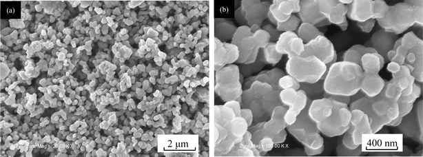 | ||
| Fig. 1 SEM images of the ‘composite’ layered material (0.5Li2MnO3·0.5LiMn0.42Ni0.42Co0.16O2) prepared by a solid state reaction method: (a) ×20.69 K; (b) ×100 K. | ||
Fig. 2 shows the initial charge and discharge profiles of the Li/0.5Li2MnO3·0.5LiMn0.42Ni0.42Co0.16O2 cells with different cut-off voltages. The current density is 5 mA g−1, and cut-off voltages are 4.4, 4.6 and 4.8 V, respectively. It is clear that the initial charge and discharge capacities are affected largely by the cut-off voltage. With adding the cut-off voltage, the discharge capacities increase largely, especially when the cut-off voltage is larger than 4.4 V. In the case when the cut-off voltage is 4.4 V, the discharge capacity of the Li/0.5Li2MnO3·0.5LiMn0.42Ni0.42Co0.16O2 cells is 96 mA h g−1. However, when the cut-off voltage increases to 4.6 V, the discharge capacity is 232 mA h g−1. Moreover, all the charge profiles of this electrode material can be divided into two distinguishing charge regions during the initial charge process. It is reported that different charge regions relate to the lithium extraction processes with different electrochemical or chemical reactions.3,4,14,15 The first charge regions below 4.4 V originate from the lithium ion extraction process from the LiMn0.42Ni0.42Co0.16O2 component,3,4,15 while the second charge region above 4.4 V is mainly due to the removal of lithium ions associated with loss of oxygen from the Li2MnO3 component.3,4,16 With the cut-off voltage increasing from 4.6 to 4.8 V, the second charge region becomes longer, and the discharge capacity increases to 272 mA h g−1. The increased capacity during this process indicates that more lithium ions associated with oxygen are extracted from the cathode materials.
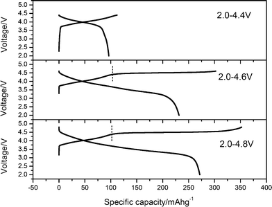 | ||
| Fig. 2 Initial charge and discharge profiles of the Li/0.5Li2MnO3·0.5LiMn0.42Ni0.42Co0.16O2 cells with different cut-off voltages. The charge and discharge curves with 4.8 V cut-off voltage were taken from ref. 4 for comparison. | ||
The electrochemical properties including charge/discharge capacity, irreversible capacity and columbic efficiency of the Li/0.5Li2MnO3·0.5LiMn0.42Ni0.42Co0.16O2 cells with different cut-off voltages are summarized in Table 1. With the cut-off voltage increasing, especially from 4.4 to 4.6 V, the irreversible capacity (IRC) loss increases largely, while the columbic efficiency decreases. Therefore, the irreversible capacity of these ‘composite’ layered materials is induced mostly by the second charge regions after 4.4 V, which is consistent with the research results of Thackeray.3Fig. 3 shows the powder X-ray diffraction patterns of the pristine electrodes and electrodes after being charged/discharged with different cut-off voltages. Highlighted X-ray diffraction patterns related to the 2θ range of 19–23° are shown in the inserts of Fig. 3. It is obvious that most Bragg diffraction peaks of all electrode materials with different cut-off voltages are indexed to the LiNiO2 unit cell with space group symmetry R![[3 with combining macron]](https://www.rsc.org/images/entities/char_0033_0304.gif) m. With the cut-off voltage increasing, all peaks shift to a lower angle, indicating that the lattice volumes enlarge. Moreover, the Bragg diffraction peaks in the 2θ range of 19–23° (the inserts of Fig. 3) are significantly weak and essentially disappear, especially when the cut-off voltage is 4.8 V.
m. With the cut-off voltage increasing, all peaks shift to a lower angle, indicating that the lattice volumes enlarge. Moreover, the Bragg diffraction peaks in the 2θ range of 19–23° (the inserts of Fig. 3) are significantly weak and essentially disappear, especially when the cut-off voltage is 4.8 V.
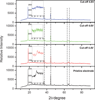 | ||
| Fig. 3 XRD patterns of the pristine and discharged states cathode electrodes of the Li/0.5Li2MnO3·0.5LiMn0.42Ni0.42Co0.16O2 cells with different cut-off voltages. | ||
| Cut off voltage/V | The 1st charge capacity/mA h g−1 | The 1st discharge capacity/mA h g−1 | IRC loss of the 1st cycle/mA h g−1 | Coulombic efficiency of the 1st cycle /% |
|---|---|---|---|---|
| 2.0–4.4 | 112 | 96 | 16 | 86 |
| 2.0–4.6 | 302 | 232 | 70 | 77 |
| 2.0–4.84 | 352 | 272 | 80 | 77 |
These results suggest that reactions above 4.4 V are no longer the reversible solid-state redox reactions accompanied by lithium ion insertion/extraction into/from the crystal lattice, and the oxygen removal from the bulk of the electrode materials leads to structural reconstruction.4 These phenomena are consistent with the research results by Naoaki Yabuuchi.1 Differently, there is no evidence of the existence of Li2CO3 after the cells discharged to 2.0 V from the 4.8 V charged state in Fig. 3, while some sharp and symmetrical peaks as the diffraction peaks of Li2CO3 appeared in the reported synchrotron X-ray diffraction profiles of the 0.5Li2MnO3–0.5LiCo1/3Ni1/3Mn1/3O2 electrode.1 These differences may be due to the different material composition and light strength of the X-ray source.
In order to understand the structure changes of the 0.5Li2MnO3·0.5LiMn0.42Ni0.42Co0.16O2 ‘composite’ layered material with different cut-off voltages, the lattice parameters of the pristine electrodes and electrodes with discharged states are calculated through the least squares method using higher six peaks of XRD patterns, as shown in Fig. 4. In general, the lattice parameters, a and c, and the lattice volume V of the electrodes with discharged state increase with the cut-off voltage increasing. Changes of these values are little when the cut-off voltages are 4.4 V, while large as in the case when the cut-off voltages are 4.6 V. The increase in the value of a, c and V is attributed to the increasing Mn3+ ion content because trivalent manganese has a larger ionic radius (0.65 Å for high-spin, and 0.58 Å for low-spin) relative to Mn4+ (0.53 Å). In addition, these results also give evidence that Li2MnO3 components are activated when the cut-off voltage is larger than 4.4 V.
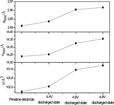 | ||
| Fig. 4 Lattice parameters of the cathode electrode materials of the Li/0.5Li2MnO3·0.5LiMn0.42Ni0.42Co0.16O2 cells with different discharged states. The lattice parameters were calculated through the least squares method using higher six peaks of XRD patterns. | ||
3.1 OCV analysis
In our previous work, we have confirmed that the electrochemical properties of these materials are kinetically controlled, the charge and discharge capacities of these materials are controlled by the current density, and the Li2MnO3 components are activated not only in the first cycle but also in the subsequent cycles.4 In order to understand their kinetically controlled process during the 1st cycle and the following cycles, we need to study the lithium ion electrochemical insertion and extraction processes in detail during different cycles.The cell in this work was first charged at a constant current density (20 mA g−1) for an interval of 1 h followed by an open-circuit stand for 2 h to allow the cell voltage to relax to a steady-state value. In the first charge process, this procedure was repeated 15 times calculated by the 1st charging capacity (302 mA h g−1/20 mA g−1 ≈ 15 h).4 In the first discharge process, this procedure was repeated 11 times calculated by the 1st discharging capacity (224 mA h g−1/20 mA g−1 ≈ 11 h).4 In the 2nd and 3rd cycles, this procedure was repeated 11 times. Fig. 5(a)(b) show the charge/discharge and OCV curves of the 0.5Li2MnO3·0.5LiMn0.42Ni0.42Co0.16O2 electrode material in the 1st, 2nd and 3rd charge and discharge processes. There are about five main reactions during the charge and discharge processes of these ‘composite’ layered materials, which have been researched in detail in our previous work.4
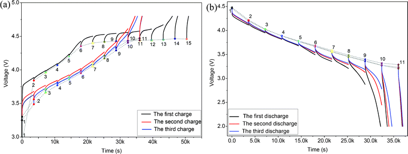 | ||
| Fig. 5 GITT and OCV curves of the 0.5Li2MnO3·0.5LiMn0.42Ni0.42Co0.16O2 electrode material in the first, second and third charges (a) and discharges (b) with a 20 mA g−1 charge/discharge current density and a time interval of 1 h. | ||
In the 1st charge process of Fig. 5(a), there is almost no overpotential observed until point 6 (OCV = 4.35 V) is reached, and the main kinetic process of lithium during this stage is associated with the lithium ion extraction reaction from the LiMn0.42Ni0.42Co0.16O2 component. Above this point, there is an obvious plateau of the charge and OCV curves, and the over-potential increases largely from point 6 (OCV = 4.35 V) to point 15 (OCV = 4.46 V), which implies that the main reaction associated with the lithium ion extraction process from the Li2MnO3 component during this stage are kinetically limited.4 In the 2nd and 3rd charge processes, there are obvious phenomena that the over-potentials decrease firstly, keep stable and then increase quickly, which implies that the electrode polarization at the beginning and end of these charge processes is large. In ref. 4, the oxidation potentials associated with the lithium ion extraction reactions from the LiMnO2 component and the Li2MnO3 component during the 2nd and 3rd charge process are about 3.5 and 4.5 V, respectively, which is well consistent with the potentials associated with the highest over-potentials in Fig. 5(a). Thus, the high over-potentials at the beginning of these charge processes are probably associated with the lithium ion extraction reaction polarization from the LiMnO2 component originated from the activated Li2MnO3 component, while the high over-potentials at the end of these charge processes are probably associated with the electrochemical polarization of the lithium ion extraction process from the unactivated Li2MnO3 component and the concentration polarization induced by the lithium ion concentration reduction of the electrode materials. Besides, the low over-potentials in the middle of the 2nd and 3rd charge processes are probably contributed to the low electrode polarization associated with the lithium ion extraction reaction from the LiMn0.42Ni0.42Co0.16O2 component.
In the 1st, 2nd and 3rd discharge processes (Fig. 5 (b)), there is one same phenomenon that the over-potentials are very small before point 6 (OCV = 3.6 V), and increase with the discharge voltage decreasing from 3.6 V (OCV of point 6) to 3.2 V (OCV of point 11). We showed that the insertion reaction of a lithium ion into the activated MnO2 after the 1st charge activation process occurred below 3.5 V during the discharge process,4 which is very close to the discharge voltage at the end of the fifth discharge curve of the 1st discharge process in Fig. 5(b). Therefore, the over-potential variation trend during the discharge process reveals that the insertion reaction of a lithium ion into the MnO2 component is kinetically limited as compared with that into the Mn0.42Ni0.42Co0.16O2 component. In addition, there is a very obvious phenomenon that all of the discharge potential plateaus below point 6 increase with the cycle number increasing. This phenomenon means that the amount of activated MnO2 component originated from the Li2MnO3 component increases with the cycle number increasing, which is also a good evidence of the continued activation reaction of the Li2MnO3 component in this material and consistent with our previous conclusion.4 In addition, the high over-potentials at the end of the discharge processes are probably associated with the side-reactions induced from the concentration polarization.
Consequently, on the basis of the analysis of OCV curves during charge and discharge processes, the lithium ion extraction processes from the LiMnO2 component and Li2MnO3 component are kinetically limited as compared with those from the LiMn0.42Ni0.42Co0.16O2 component, and the lithium ion insertion processes into the MnO2 component are kinetically limited as compared with those into the Mn0.42Ni0.42Co0.16O2 component. These results are consistent with the analysis below and testified by activation energy analysis.
3.2 GITT analysis
In order to discuss the kinetic processes of the lithium ion extraction and insertion reaction in the 0.5Li2MnO3·0.5LiMn0.42Ni0.42Co0.16O2 electrode material in detail and quantize the lithium ion transfer speed inside this ‘composite’ material. The chemical diffusion coefficient of a lithium ion (DLi+) in the active material of this ‘composite’ material was introduced in this work. The chemical diffusion coefficient of a lithium ion (DLi+) is an important kinetic parameter for lithium ion insertion and extraction reactions in intercalation materials, which can be got from the electrochemical techniques such as galvanostatic intermittent titration (GITT), potentiostatic intermittent titration (PITT), EIS and CV.17–23 Among these techniques, GITT based on chronopotentiometry at nearly thermodynamic equilibrium conditions is a reliable technique to determine the chemical diffusion coefficient of lithium ion in intercalation materials.17–23 Thus, firstly, the lithium ion diffusion coefficient in this ‘composite’ material during a charge and discharge process is studied in detail by the GITT technique.On the basis of the GITT measurement, the diffusion coefficient of lithium ions in the 0.5Li2MnO3·0.5LiMn0.42Ni0.42Co0.16O2 compound can be determined by solving Fick’s second law of diffusion and calculated by the following eqn (1):20–23
 | (1) |
For a single titration at 4.26 V, the applied current flux and the resulting voltage profile during the 1st charge process for 0.5Li2MnO3·0.5LiMn0.42Ni0.42Co0.16O2 electrode material is shown in Fig. 6(a), labeled with different parameters, E0, Es, τ, t0, t0+τ, Eτ and Es. If the relationship of the cell voltage during the time period τ versus τ1/2 shows straight line behavior, as shown in Fig. 6(b), then eqn (1) can be further simplified as eqn (2):20–23
 | (2) |
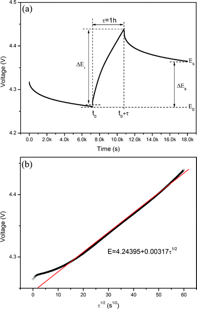 | ||
| Fig. 6 (a) Single titration at 4.26 V during GITT measurement of the 0.5Li2MnO3·0.5LiMn0.42Ni0.42Co0.16O2 electrode material with representation of different parameters. (b) Relationship of the cell voltage for the above titration and τ1/2. | ||
Fig. 7(a) shows the variation of the lithium ion diffusion coefficient (DLi+) as a function of OCV in the 1st, 2nd and 3rd charge processes. It is clear that the DLi+ in the 1st charge process is about 10−14 cm2 s−1 when the OCV is lower than 4.2 V, and then decreases to 10−17 cm2 s−1 with the OCV increasing to about 4.5 V, associating with the plateau charge process. This phenomenon shows clearly that the reaction kinetics during the 1st charge process includes two regions, and the electrochemical reaction in the last region is severely sluggish. The sluggish reaction maybe attributes to the high kinetic barriers associated with the lithium ion diffusion in the Li2MnO3 component and concentration polarization at the end of the charge process. The DLi+ of the 2nd and 3rd charge processes also show a similar variation trend to that of the 1st charge process. However, the DLi+ before 4.2 V (OCV) of the 2nd and 3rd charge processes are a little smaller than that of the 1st charge process, which means that the lithium ion diffusion speed in the active material before 4.2 V (OCV) decreases after the 1st cycle, which is very different from the conventional cathode material such as LiCoO224,25 and LiMn2O4.24,26–28 This may be attributed to the sluggish reaction associated with the lithium ion extraction from the LiMnO2 component after the 1st cycle, which is well consistent with the OCV analysis. In addition, after the 1st cycle, the smallest DLi+ during the 2nd and 3rd charge processes is about 10−16 cm2 s−1 (OCV is about 4.5 V), and is still much smaller than 10−14 cm2 s−1 (the DLi+ when the OCV is smaller than 4.2 V). This phenomenon indicates that the unactivated Li2MnO3 component in this material after the 1st cycle still exists and can be activated in subsequent charge processes. These research results are well consistent with our findings of these ‘composite’ materials4, but different from the research results by Zhe Li et al., who indicate that all of the Li2MnO3 components can be activated after the 1st cycle.18 The difference may be attributed to the different local structures of these materials induced from the different element compositions and preparation methods.
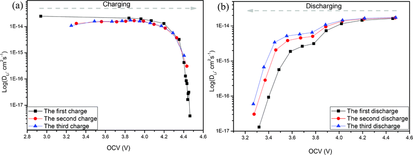 | ||
| Fig. 7 Li+ diffusion coefficients calculated from the GITT curves for the 0.5Li2MnO3·0.5LiMn0.42Ni0.42Co0.16O2 electrode material as a function of the cell voltage (OCV) during the charge process. | ||
Fig. 7(b) shows the variation of the lithium ion diffusion in the 1st, 2nd and 3rd discharge processes. It shows that there are obvious three regions with the OCV decreasing. Based on the OCV analysis in Fig. 5, the first plateau between about 4.5 V (OCV) and 3.9 V (OCV) may be attributed to the insertion reaction of a lithium ion into the Mn0.42Ni0.42Co0.16O2 component, and the second plateau from about 3.8 V (OCV) to 3.5 V (OCV) may be attributed to the lithium ion insertion reaction in the MnO2 component originated from the Li2MnO3 component. The immediate decrease DLi+ from 3.5 V (OCV) to 3.3 V (OCV) may be attributed to the large concentration polarization at the end of the discharge processes.
3.3 EIS analysis
In order to analyze the kinetic process of the lithium ion at the electrode/electrolyte interface, EIS technique is also introduced in this work. Electrochemical impedance measurements of the 0.5Li2MnO3·0.5LiMn0.42Ni0.42Co0.16O2 electrode materials during the 1st, 2nd and 3rd charge and discharge process were carried out with different states after the cell rests for 2 h.Fig. 8 shows the Nyquist plots of this material during the 1st charge and discharge process. All of the Nyquist plots except for that of the fresh cell show two semicircles at high and middle frequencies, and a slope line at low frequency. Based on the previous research on this type layered cathode materials,18,20,23 the semicircles in the high frequency can be attributed to the lithium ion diffusion through the SEI film, the semicircle in the middle frequency is associated with the charge transfer reaction, and the slope line appearing in the low frequency is attributed to the lithium ion diffusion (Warburg diffusion) in the electrode material. During the 1st charge process, the variation of the Nyquist plot with different states shows obvious two stages. When the OCV is lower than 4.068 V, the semicircle radiuses in the high and middle frequencies decrease with the OCV increasing (shown in Fig. 8(a)), while the semicircle radius in the middle frequency increases with the OCV increasing from 4.198 V to the end of charge process (Fig. 8(b)). In the discharge process, as shown in Fig. 8(c), the Nyquist plots also show two semicircles and a slope line. The semicircle radius in the middle frequency decreases firstly and then increases with the OCV decreasing from 4.457 V to the end of the discharge process.
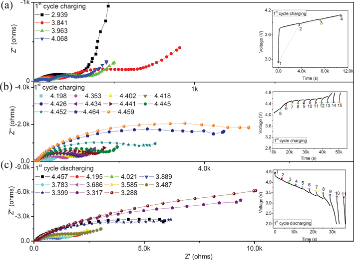 | ||
| Fig. 8 Plots for the 0.5Li2MnO3·0.5LiMn0.42Ni0.42Co0.16O2 electrode material at different OCV during the first charge and discharge processes. | ||
The Nyquist plots during the 2nd and 3rd charge/discharge processes are shown in Fig. 9. The semicircle radiuses in the middle frequency decrease firstly and then increase with the OCV increasing from around 3.3 V to 4.5 V during the 2nd and 3rd charge processes. During the discharge process, the variation trend of the Nyquist plots also presents a similar phenomenon, the contribution from the lithium ion transfer in the electrode/electrolyte interface decreases firstly and then increases with the OCV decreasing from about 4.5 V to 3.2 V.
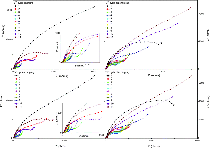 | ||
| Fig. 9 Nyquist plots for the 0.5Li2MnO3·0.5LiMn0.42Ni0.42Co0.16O2 electrode material at different stages during the second and third charge and discharge processes. | ||
The EIS data can be analyzed by the equivalent circuit given in the inset of Fig. 10, and the respective circuit elements are deduced by fitting the experimental data points with this equivalent circuit. In the equivalent circuit, Re represents the resistive contribution from the electrolyte resistance and cell components, Rs and Cs represent the resistance and associated capacitance, respectively, associating with the high frequency semicircle, Rct and Cdl represent the charge transfer resistance and its associated double-layer capacitance, respectively, associating with the low frequency semicircle, and W is the Warburg impedance related to the lithium ion diffusion in the electrode material.
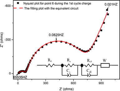 | ||
| Fig. 10 Typical Nyquist and fitting plots using the equivalent circuit. | ||
All of the fitted impedance parameters (Re, Rs and Rct) of the 0.5Li2MnO3·0.5LiMn0.42Ni0.42Co0.16O2 electrode material during the 1st, 2nd and 3rd charge/discharge processes with different OCV are presented in Fig. 11. Obviously, the main impedance of this material is contributed to the charge transfer resistance during the first three charge and discharge processes. In the 1st charge process, shown in Fig. 11(a), there are clearly three stages of the Rct curve with the OCV increasing, and described as follows. Firstly, the Rct keeps stable at about 100–200 Ω when the OCV is located between 3.841 V (point 2 in Fig. 5(a)) and 4.198 V (point 5 in Fig. 5(a)), associating with the lithium ion extraction process at the interface between the LiMn0.42Ni0.42Co0.16O2 component and the electrolyte. And then, Rct increases slowly from 487 to 901 Ω with OCV increasing from 4.353 V (point 6 in Fig. 5(a)) to 4.434 V (point 10 in Fig. 5(a)), associating with the lithium ion extraction process at the interface between the Li2MnO3 component and the electrolyte. Finally, the Rct increases sharply from 1128 to 4468 Ω with the charge process from 4.441 V (point 11 in Fig. 5(a)) to 4.459 V (point 15 in Fig. 5(a)), which is contributed to the high concentration polarization at the end of charge process.
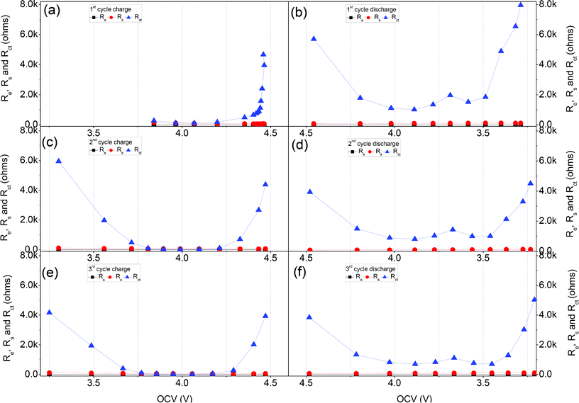 | ||
| Fig. 11 Re, Rs and Rct obtained by fitting the impedance data for the 1st, 2nd and 3rd cycles in Fig. 8 and Fig. 9 during the charge and discharge process, with the equivalent circuit shown in Fig. 10. | ||
Based on the EIS analysis of the 1st charge process of the 0.5Li2MnO3·0.5LiMn0.42Ni0.42Co0.16O2 electrode material, it appears that the lithium ion transfers at the interface between the electrode and electrolyte during the Li2MnO3 component activation stage are very large compared to those during the LiMn0.42Ni0.42Co0.16O2 component electrochemical reaction stage.
Fig. 11(c) and Fig. 11(e) show the variation trend of the Re, Rs and Rctversus OCV during the 2nd and 3rd charge processes with varying OCV. It is obvious that the Rct decreases when the OCV increases from about 3.3 to 3.8 V, remains stable from about 3.8 to 4.2 V, and increases from about 4.2 to 4.5 V. The high Rct before 3.8 V (OCV) maybe attribute to the lithium ion transfer resistance at the interface between the LiMnO2 component electrode in local region and electrolyte. And, the increased Rct between 4.2 V (OCV) and 4.5 V (OCV) are maybe associated with the lithium ion charge transfer resistance at the interface between the unactivated Li2MnO3 component and electrolyte and the concentration polarization.
Based on the OCV analysis in Fig. 5(b), during the discharge processes of the 1st, 2nd and 3rd cycles in Fig. 11 (b)(d)(f), the Rct between 4.2 V (OCV) and 3.7 V (OCV) associated with the lithium ion insertion into the Mn0.42Ni0.42Co0.16O2 component is a little smaller than that between 3.7 V (OCV) and 3.5 V (OCV) associated with the lithium ion insertion into the MnO2 component. Therefore, the lithium ion transfer resistance at the electrode/electrolyte of the MnO2 component activated from Li2MnO3 component is a little larger than that of the Mn0.42Ni0.42Co0.16O2 component. Besides, the high Rct at the end of the discharge process maybe contribute to the large concentration polarization induced by the increased lithium ion concentration in the active material.
3.4 Activation energy analysis
Activation energies of the interface reactions during varying charge and discharge voltages are also introduced in this work to investigate the kinetics of the charge-transfer reaction of the 0.5Li2MnO3·0.5LiMn0.42Ni0.42Co0.16O2 electrode material. The study on the activation energy is useful for clear understanding of the kinetic trend of this material with different components in different stages because the activation energy value indicates the essential kinetics of the reaction without the influence of effective surface area, activity of reactants and temperature.11 In this work, for the detailed activation energy calculation and discussion, four research points during the 1st charge and discharge process, and three research points during the 2nd charge process are chosen based on the redox-reaction and dQ/dV curves of these ‘composite’ materials. All of these points are marked in the insert figures of Fig. 12. The dQ/dV (Q is the capacity and V is the voltage of the cell) curves are calculated from numerical data in the 1st charge/discharge and 2nd charge curve of this ‘composite’ material with 20 mA g−1 charge/discharge current density.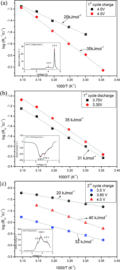 | ||
| Fig. 12 Activation energy of the 1st charge/discharge processes and 2nd charge process. | ||
The charge/discharge activation energy can be calculated using the following equation.11
| 1/Rct = Aexp(−Ea/RT) | (3) |
In which, the symbols A, Ea, R and T denote frequency factor, activation energy, gas constant and absolute temperature, respectively.
Fig. 12(a) shows the Arrhenius plots of the interfacial conductivity (1/Rct) versus different temperature during the 1st charge process. Two potentials associated with the lithium ion extraction reactions from the LiMn0.42Ni0.42Co0.16O2 component (4.0 V in dQ/dV curve) and the Li2MnO3 component (4.5 V in dQ/dV curve) are chosen for discussion.4 It is obvious that the interface reaction activation energy of the lithium ion extracting from the Li2MnO3 component is about 35 kJ mol −1, which is much larger than 20 kJ mol −1 associated with the lithium ion extracting from the LiMn0.42Ni0.42Co0.16O2 component. These results are well consistent with the OCV and EIS analysis results. Besides, it can be clearly seen from Fig. 12(a) that the interface reaction of the lithium ion extracting from the Li2MnO3 component is more sensitive to temperature than that of the lithium ion extracting from the LiMn0.42Ni0.42Co0.16O2 component. This phenomenon means that temperature would affect the activation process of the Li2MnO3 component, which will be discussed in detail in the future.
The Arrhenius plots of the interfacial conductivity (1/Rct) versus varying temperature during the 1st discharge process are shown in Fig. 12(b). The reaction associated with 3.75 V is mainly contributed to the lithium ion insertion process into the Mn0.42Ni0.42Co0.16O2 component, while the reaction of 3.35 V is mainly associated with the lithium ion insertion process into the MnO2 component.4 Therefore, Fig. 12(b) reveals that the interface reaction of the lithium ion into the Mn0.42Ni0.42Co0.16O2 component is a little easier than that of the lithium ion into the MnO2 component originated from the Li2MnO3 component. In addition, the interface reaction activation energies during the 2nd charge process are also presented in Fig. 12(c), and the researched potentials of 3.5 and 3.85 V are associated with the lithium ion extraction processes from the novel LiMnO2 component and the LiMn0.42Ni0.42Co0.16O2 component.4 Therefore, it is clear that the interface reaction activation energy (32 kJ mol −1) of the lithium ion extracted from the novel LiMnO2 component is much larger than that (20 kJ mol−1) of lithium ion extracted from the LiMn0.42Ni0.42Co0.16O2 component. As for the largest interface reaction activation energy (40 kJ mol −1) associated with the 4.5 V potential, it is most probably contributed to the large transfer barrier of lithium ion at the interface of the unactivated Li2MnO3 component. Besides, other reactions at the 4.5 V potential maybe also exist and need to be confirmed in the future. In this work, all of the interface reaction activation energy research results can well support the OCV, GITT and EIS analysis results.
4. Conclusions
The ‘composite’ layered material of 0.5Li2MnO3·0.5LiMn0.42Ni0.42Co0.16O2 had been prepared by the solid state reaction method, and was characterized by XRD and SEM methods. The kinetics of the electrochemical insertion and extraction of lithium ions during the first three cycles in this material were investigated in detail by the open circuit voltage (OCV), galvanostatic intermittent titration technique (GITT), and electrochemical impedance spectroscopy (EIS) methods. The activation energies of interfacial lithium ion transfer in different oxidation-reduction reactions were evaluated from the temperature-dependence of lithium ion transfer resistance. The results show that the electrochemical kinetics of the lithium ion extraction and insertion reactions in the first three cycles are very different from that of conventional cathode materials as the case of this material is charged to larger than 4.4 V. The rate properties of this ‘composite’ material are mainly controlled by the Li2MnO3 component composited in this material. Even though this component can be activated after the 1st charge process, the novel MnO2 and LiMnO2 component still have lower lithium ion diffusion coefficient and higher interface reaction barriers. Thus, in order to improve the rate performance of this composite material, some methods are introduced based on this work. To decrease the proportion of the Li2MnO3 component, reducing the distance of lithium ion diffusion and coat material associated with low interface reaction barrier on the surface of these ‘composite’ materials may improve their rate performance.Acknowledgements
This work was supported by the Innovative Basic Research Toward Creation of High-performance Battery in the Funding Program for World-leading Innovative R&D on Science and Technology.References
- N. Yabuuchi, K. Yoshii, S. T. Myung, I. Nakai and S. Komaba, J. Am. Chem. Soc., 2011, 133, 4404–4419 CrossRef CAS.
- T. Ohzuku, M. Nagayama, K. Tsuji and K. Ariyoshi, J. Mater. Chem., 2011, 21, 10179–10188 RSC.
- M. M. Thackeray, S. H. Kang, C. S. Johnson, J. T. Vaughey, R. Benedek and S. A. Hackney, J. Mater. Chem., 2007, 17, 3112–3125 RSC.
- H. Yu, H. Kim, Y. Wang, P. He, D. Asakura, Y. Nakamura and H. Zhou, Phys. Chem. Chem. Phys., 2012, 14, 6584–6595 RSC.
- P. He, H. J. Yu, D. Li and H. S. Zhou, J. Mater. Chem., 2012, 22, 3680–3695 RSC.
- H. S. Kim, J. H. Jeong, B. S. Jin, W. S. Kim and G. X. Wang, J. Power Sources, 2011, 196, 3439–3442 CrossRef.
- A. Ito, Y. Sato, T. Sanada, M. Hatano, H. Horie and Y. Ohsawa, J. Power Sources, 2011, 196, 6828–6834 CrossRef CAS.
- S. H. Kang, V. G. Pol, I. Belharouak and M. M. Thackeray, J. Electrochem. Soc., 2010, 157, A267–a271 CrossRef CAS.
- Z. H. Lu and J. R. Dahn, J. Electrochem. Soc., 2002, 149, A815–a822 CrossRef CAS.
- D. Y. W. Yu and K. Yanagida, J. Electrochem. Soc., 2011, 158, A1015–a1022 CrossRef CAS.
- Y. Yamada, Y. Iriyama, T. Abe and Z. Ogumi, J. Electrochem. Soc., 2010, 157, A26–a30 CrossRef CAS.
- Y. Yamada, F. Sagane, Y. Iriyama, T. Abe and Z. Ogumi, J. Phys. Chem. C, 2009, 113, 14528–14532 CAS.
- Y. Yamada, Y. Iriyama, T. Abe and Z. Ogumi, Langmuir, 2009, 25, 12766–12770 CrossRef CAS.
- S. H. Kang, P. Kempgens, S. Greenbaum, A. J. Kropf, K. Amine and M. M. Thackeray, J. Mater. Chem., 2007, 17, 2069–2077 RSC.
- C. S. Johnson, N. C. Li, C. Lefief, J. T. Vaughey and M. M. Thackeray, Chem. Mater., 2008, 20, 6095–6106 CrossRef CAS.
- A. R. Armstrong, M. Holzapfel, P. Novak, C. S. Johnson, S. H. Kang, M. M. Thackeray and P. G. Bruce, J. Am. Chem. Soc., 2006, 128, 8694–8698 CrossRef CAS.
- K. Tang, X. Q. Yu, J. P. Sun, H. Li and X. J. Huang, Electrochim. Acta, 2011, 56, 4869–4875 CrossRef CAS.
- Z. Li, F. Du, X. F. Bie, D. Zhang, Y. M. Cai, X. R. Cui, C. Z. Wang, G. Chen and Y. J. Wei, J. Phys. Chem. C, 2010, 114, 22751–22757 CAS.
- D. W. Dees, S. Kawauchi, D. P. Abraham and J. Prakash, J. Power Sources, 2009, 189, 263–268 CrossRef CAS.
- K. M. Shaju, G. V. S. Rao and B. V. R. Chowdari, Electrochim Acta, 2004, 49, 1565–1576 CAS.
- K. M. Shaju, G. V. S. Rao and B. V. R. Chowdari, J. Mater. Chem., 2003, 13, 106–113 RSC.
- K. M. Shaju, G. V. S. Rao and B. V. R. Chowdari, J. Electrochem. Soc., 2003, 150, A1–a13 CrossRef CAS.
- K. M. Shaju, G. V. S. Rao and B. V. R. Chowdari, Electrochim. Acta, 2003, 48, 2691–2703 CrossRef CAS.
- J. Xie, N. Imanishi, T. Matsumura, A. Hirano, Y. Takeda and O. Yamamoto, Solid State Ionics, 2008, 179, 362–370 CrossRef CAS.
- H. Xia, L. Lu and G. Ceder, J. Power Sources, 2006, 159, 1422–1427 CrossRef CAS.
- M. Y. Saidi, J. Barker and R. Koksbang, J. Solid State Chem., 1996, 122, 195–199 CrossRef CAS.
- K. Dokko, M. Mohamedi, M. Umeda and I. Uchida, J. Electrochem. Soc., 2003, 150, A425–a429 CrossRef CAS.
- J. Xie, T. Tanaka, N. Imanishi, T. Matsumura, A. Hirano, Y. Takeda and O. Yamamoto, J. Power Sources, 2008, 180, 576–581 CrossRef CAS.
| This journal is © The Royal Society of Chemistry 2012 |
