The influence of charge ordering on the phase stability of spinel LiNi2O4
Akihide
Kuwabara
*a,
Craig A. J.
Fisher
a,
Yumi H.
Ikuhara
a,
Hiroki
Moriwake
a,
Hideki
Oki
bc and
Yuichi
Ikuhara
ad
aNanostructures Research Laboratory, Japan Fine Ceramics Center, Nagoya, 456-8587, Japan. E-mail: kuwabara1974@gmail.com
bToyota Motor Corporation, Susono, 410-1193, Japan
cGraduate School of Frontier Sciences, The University of Tokyo, Tokyo, 113-0033, Japan
dInstitute of Engineering Innovation, The University of Tokyo, Tokyo, 113-8656, Japan
First published on 25th October 2012
Abstract
The transition metal ions in spinel LiNi2O4 are commonly assumed to be in a single charge state and uniformly distributed throughout the crystal lattice. However, multivalent Ni can exist in a number of different charge states simultaneously within the crystal, whilst still maintaining overall charge neutrality. By carrying out a systematic study of possible charge states of Ni and their distribution in LiNi2O4 using first-principles calculations within the framework of density functional theory, we show that two charge-ordered phases are more stable than the charge-disordered spinel phase: (a) an orthorhombic phase containing Ni3+ and Ni4+ ions in a 1![[thin space (1/6-em)]](https://www.rsc.org/images/entities/char_2009.gif) :
:![[thin space (1/6-em)]](https://www.rsc.org/images/entities/char_2009.gif) 1 ratio resulting in Imma symmetry, and (b) a cubic phase with Ni2+ and Ni4+ in a 1
1 ratio resulting in Imma symmetry, and (b) a cubic phase with Ni2+ and Ni4+ in a 1![[thin space (1/6-em)]](https://www.rsc.org/images/entities/char_2009.gif) :
:![[thin space (1/6-em)]](https://www.rsc.org/images/entities/char_2009.gif) 3 ratio with P4332 symmetry. Our results indicate that charge ordering is an important process in stabilizing the spinel phase of LiNi2O4, and should not be ignored in any quantitative study. Our findings are of particular importance for elucidating the relative stabilities of the spinel phase and layered phase of Li1−xNi2O4, a delithiated form of lithium secondary battery cathode material LiNiO2.
3 ratio with P4332 symmetry. Our results indicate that charge ordering is an important process in stabilizing the spinel phase of LiNi2O4, and should not be ignored in any quantitative study. Our findings are of particular importance for elucidating the relative stabilities of the spinel phase and layered phase of Li1−xNi2O4, a delithiated form of lithium secondary battery cathode material LiNiO2.
Introduction
The LixNiO2 system is being studied intensively in the search for improved cathode materials for Li-ion secondary batteries. The fully lithiated end member LiNiO2 has an α-NaFeO2 structure (space group R![[3 with combining macron]](https://www.rsc.org/images/entities/char_0033_0304.gif) m)1–3 composed of alternate layers of Li and NiO2 in the c direction. In its role as a cathode, Li ions are deintercalated and intercalated between the NiO2 layers during the charge and discharge processes, respectively. Previous experimental4–6 and theoretical7,8 studies have shown that ordering of Li and Li vacancies occurs in the Li layers when x deviates from 1.
m)1–3 composed of alternate layers of Li and NiO2 in the c direction. In its role as a cathode, Li ions are deintercalated and intercalated between the NiO2 layers during the charge and discharge processes, respectively. Previous experimental4–6 and theoretical7,8 studies have shown that ordering of Li and Li vacancies occurs in the Li layers when x deviates from 1.
One problem afflicting the LixNiO2 system is the low thermal stability of the layered structure. Previous studies have revealed that LixNiO2 decomposes into layer-type LiNiO2 and spinel-type LiNi2O4 at temperatures around 200 °C for Li concentrations of 0.5 < x < 1.9–11 When x is less than 0.5, LixNiO2 transforms into spinel LiNi2O4 and then into a disordered rock-salt structure with the simultaneous release of oxygen gas. The formation of LiNi2O4 greatly alters the properties of LixNiO2, degrading its performance as a cathode. In addition, the layer-to-spinel transformation is known to be an exothermic reaction, and such heat generation seriously degrades the durability of batteries.
Spinel-type LiNi2O4 was first reported by Thomas et al.12 almost 20 years ago based on X-ray diffraction patterns of LixNiO2 samples, in which Li ions had been electrochemically extracted at elevated temperatures, but its properties are known only to a limited extent. For example, LixNiO2 with low Li content is known to decompose into a disordered rock-salt type Ni–Li–O solid solution above 300 °C.10 Because it is difficult to obtain samples of pure spinel LiNi2O4 by direct synthesis, however, theoretical calculations offer an attractive alternative means of examining this material. For example, Chazel et al. calculated the local spin density in spinel LiNi2O4 using density functional theory (DFT) and analysed the 7Li neutron magnetic resonance (NMR) shifts based on their results.13 Wang et al. have also systematically computed the thermal stabilities of LixMO2 (M = Ni, Co, Mn) compounds with layer and spinel structures.14
Given the importance of layer-structured transition metal oxides to lithium ion battery technology and the continuing drive to develop improved cathodes (safer, higher energy and power densities at lower cost), there is a strong need for a better understanding of this material at the electronic and atomic levels. In this article, we investigate the energy states and electronic structure of spinel LiNi2O4 using first-principles calculations for the purpose of understanding the layer-to-spinel phase transformation in the LixNiO2 system. Preliminary DFT calculations have revealed that a charge-ordered phase of LiNi2O4 is more stable than the ideal spinel phase.15 We focus on the role of the charge distribution of Ni ions in determining the relative phase stability of spinel LiNi2O4.
Computational methodology
First-principles total energy calculations were performed using the projector augmented wave method16 and the generalized gradient approximation (GGA),17 as implemented in the VASP code.18 Plane waves up to 500 eV were used as basis sets. Valence electron configurations of the potentials were taken as 1s2 2s1 for Li, 3p6 3d8 4s2 for Ni, and 2s2 2p4 for O. The radial cutoffs of the PAW potentials of Li, Ni and O were 2.05, 2.00 and 1.52 Å, respectively. The strong correlation of Ni 3d electrons was taken into account using the GGA+U method.19 The value of U was set at 6 eV.14The space group of the ideal spinel structure is Fd![[3 with combining macron]](https://www.rsc.org/images/entities/char_0033_0304.gif) m. In this structure, all Ni ions are located on 16d sites with octahedral coordination (NiO6 units) and are symmetrically equivalent. Their nominal valence state is +3.5. If charge separation occurs, however, charge-ordered phases of LiNi2O4 are also possible. In this study, two types of model were used to examine charge ordering in LiNi2O4. In the first, equal numbers of Ni3+ and Ni4+ ions were distributed over the 16d sites. In the second, Ni ions were separated into 4 Ni2+ and 12 Ni4+ ions per unit cell. We refer to the former and latter models, respectively, as the 1
m. In this structure, all Ni ions are located on 16d sites with octahedral coordination (NiO6 units) and are symmetrically equivalent. Their nominal valence state is +3.5. If charge separation occurs, however, charge-ordered phases of LiNi2O4 are also possible. In this study, two types of model were used to examine charge ordering in LiNi2O4. In the first, equal numbers of Ni3+ and Ni4+ ions were distributed over the 16d sites. In the second, Ni ions were separated into 4 Ni2+ and 12 Ni4+ ions per unit cell. We refer to the former and latter models, respectively, as the 1![[thin space (1/6-em)]](https://www.rsc.org/images/entities/char_2009.gif) :
:![[thin space (1/6-em)]](https://www.rsc.org/images/entities/char_2009.gif) 1 and 1
1 and 1![[thin space (1/6-em)]](https://www.rsc.org/images/entities/char_2009.gif) :
:![[thin space (1/6-em)]](https://www.rsc.org/images/entities/char_2009.gif) 3 charge-ordered (CO) phases.
3 charge-ordered (CO) phases.
When in octahedral coordination, Ni2+ has a spin configuration of t2g[↑↑↑↓↓↓]eg[↑↑] (2 Bohr). Assuming a low-spin state, the spin configurations of Ni3+ and Ni4+ are t2g[↑↑↑↓↓↓]eg[↑] (1 Bohr) and t2g[↑↑↑↓↓↓] (0 Bohr), respectively. Thus, Ni2+ and Ni3+ are magnetic but Ni4+ is non-magnetic. In charge-ordered LiNi2O4 models, initial magnetic moments were set explicitly to these values, as appropriate for each site. The separation of Ni charges over different sites breaks the fcc symmetry of the ideal spinel structure, resulting in a series of different, i.e. symmetrically non-equivalent, configurations that need to be examined individually. In total, the electronic structures and total energies of 114 configurations, 95 for 1![[thin space (1/6-em)]](https://www.rsc.org/images/entities/char_2009.gif) :
:![[thin space (1/6-em)]](https://www.rsc.org/images/entities/char_2009.gif) 1 CO and 19 for 1
1 CO and 19 for 1![[thin space (1/6-em)]](https://www.rsc.org/images/entities/char_2009.gif) :
:![[thin space (1/6-em)]](https://www.rsc.org/images/entities/char_2009.gif) 3 CO models, were calculated; all systems were initially assumed to be in the ferromagnetic state. The size of the simulation cell used was that of the conventional unit cell of spinel (56 atoms). A 3 × 3 × 3 k-point sampling mesh was used in all cases, which provided an energy convergence of less than 2 meV per LiNi2O4 formula unit (f.u.). Crystal structures were fully relaxed until residual forces were less than 0.02 eV Å−1. Calculations were also performed with magnetic ions in an antiferromagnetic state for the lowest energy ferromagnetic structures. All crystal structure diagrams and related volumetric 3D data were produced using the visualization program VESTA.20
3 CO models, were calculated; all systems were initially assumed to be in the ferromagnetic state. The size of the simulation cell used was that of the conventional unit cell of spinel (56 atoms). A 3 × 3 × 3 k-point sampling mesh was used in all cases, which provided an energy convergence of less than 2 meV per LiNi2O4 formula unit (f.u.). Crystal structures were fully relaxed until residual forces were less than 0.02 eV Å−1. Calculations were also performed with magnetic ions in an antiferromagnetic state for the lowest energy ferromagnetic structures. All crystal structure diagrams and related volumetric 3D data were produced using the visualization program VESTA.20
Results and discussion
Crystal structures and their stability
Examination of the total energies of the 114 different systems reveals that some charge-ordering configurations are more stable than the ideal spinel (Fd![[3 with combining macron]](https://www.rsc.org/images/entities/char_0033_0304.gif) m) phase (Fig. 1(a)). Among the ordered phases, the 1
m) phase (Fig. 1(a)). Among the ordered phases, the 1![[thin space (1/6-em)]](https://www.rsc.org/images/entities/char_2009.gif) :
:![[thin space (1/6-em)]](https://www.rsc.org/images/entities/char_2009.gif) 1 CO phase in orthorhombic space group Imma and the 1
1 CO phase in orthorhombic space group Imma and the 1![[thin space (1/6-em)]](https://www.rsc.org/images/entities/char_2009.gif) :
:![[thin space (1/6-em)]](https://www.rsc.org/images/entities/char_2009.gif) 3 CO phases in cubic space groups P4332 and P4132 are the most stable configurations. The P4332 and P4132 1
3 CO phases in cubic space groups P4332 and P4132 are the most stable configurations. The P4332 and P4132 1![[thin space (1/6-em)]](https://www.rsc.org/images/entities/char_2009.gif) :
:![[thin space (1/6-em)]](https://www.rsc.org/images/entities/char_2009.gif) 3 CO phases are enantiomorphs, and essentially equal in energy. In the remainder we will thus confine ourselves to describing the P4332 phase only. Optimized lattice constants for unit cells of Imma and P4332 LiNi2O4 are listed in Table 1. The calculated lattice constant of the ideal LiNi2O4 spinel, 8.157 Å, is about 1.4% larger than the experimentally measured value, 8.041 Å,12 a typical degree of overestimation by GGA; of the charge-ordered phases, the one with the unit cell most similar in size to that of the conventional spinel cell is P4332. The volume of the unit cell of the Imma 1
3 CO phases are enantiomorphs, and essentially equal in energy. In the remainder we will thus confine ourselves to describing the P4332 phase only. Optimized lattice constants for unit cells of Imma and P4332 LiNi2O4 are listed in Table 1. The calculated lattice constant of the ideal LiNi2O4 spinel, 8.157 Å, is about 1.4% larger than the experimentally measured value, 8.041 Å,12 a typical degree of overestimation by GGA; of the charge-ordered phases, the one with the unit cell most similar in size to that of the conventional spinel cell is P4332. The volume of the unit cell of the Imma 1![[thin space (1/6-em)]](https://www.rsc.org/images/entities/char_2009.gif) :
:![[thin space (1/6-em)]](https://www.rsc.org/images/entities/char_2009.gif) 1 CO phase is about half that of the conventional spinel cell. This orthorhombic unit cell can be converted into a pseudo-spinel with volume √2 aImma × √2 bImma × cImma, where a ≅ 7.97, b ≅ 7.97, and c ≅ 8.39 Å.
1 CO phase is about half that of the conventional spinel cell. This orthorhombic unit cell can be converted into a pseudo-spinel with volume √2 aImma × √2 bImma × cImma, where a ≅ 7.97, b ≅ 7.97, and c ≅ 8.39 Å.
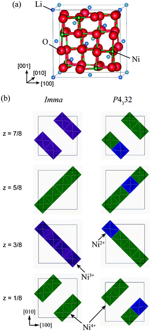 | ||
Fig. 1 (a) Unit cell of the ideal Fd3m structure of LiNi2O4, and (b) schematic representations of Ni charge configurations in 1![[thin space (1/6-em)]](https://www.rsc.org/images/entities/char_2009.gif) : :![[thin space (1/6-em)]](https://www.rsc.org/images/entities/char_2009.gif) 1 charge-ordered Imma and 1 1 charge-ordered Imma and 1![[thin space (1/6-em)]](https://www.rsc.org/images/entities/char_2009.gif) : :![[thin space (1/6-em)]](https://www.rsc.org/images/entities/char_2009.gif) 3 charge-ordered P4332 phases. 3 charge-ordered P4332 phases. | ||
| Imma | P4332 | |||
|---|---|---|---|---|
| a/Å | 5.641 | 8.111 | ||
| b/Å | 5.635 | |||
| c/Å | 8.393 | |||
| Z | 4 | 8 | ||
| V (Å3/f.u.) | 66.706 | 66.699 | ||
| Li | 4e | (0, 1/4, 0.362) | (0.246, 0.246, 0.246) | |
| Ni | 4d | (1/4, 1/4, 3/4) (3+) | 4b | (5/8, 5/8, 5/8) (2+) |
| 4d | (1/4, 1/4, 3/4) (4+) | 12d | 12d (1/8, 0.383, 0.867) (4+) | |
| O | 8i | (0.279, 0.250, 0.501) | 8c | (0.866, 0.866, 0.866) |
| 8h | (0.000, 0.526, 0.224) | 24e | (0.846, 0.356, 0.377) | |
Fig. 1(b) shows schematically the charge-ordered configurations in the Imma and P4332 phases, with the Imma phase structure shown in its pseudo-cubic form for ease of comparison with the ideal spinel structure. The Imma 1![[thin space (1/6-em)]](https://www.rsc.org/images/entities/char_2009.gif) :
:![[thin space (1/6-em)]](https://www.rsc.org/images/entities/char_2009.gif) 1 CO phase is isomorphic with LiVCuO4,21 in which Li+ ions occupy octahedral sites. LiO6 octahedra share edges and form a chain structure parallel to (001). Li and Cu layers alternate in the [001] direction. Similarly, the Imma 1
1 CO phase is isomorphic with LiVCuO4,21 in which Li+ ions occupy octahedral sites. LiO6 octahedra share edges and form a chain structure parallel to (001). Li and Cu layers alternate in the [001] direction. Similarly, the Imma 1![[thin space (1/6-em)]](https://www.rsc.org/images/entities/char_2009.gif) :
:![[thin space (1/6-em)]](https://www.rsc.org/images/entities/char_2009.gif) 1 CO phase of LiNi2O4 has alternate layers of Ni3+ and Ni4+ planes in the [001] direction, as seen in Fig. 1(b). The P4332 1
1 CO phase of LiNi2O4 has alternate layers of Ni3+ and Ni4+ planes in the [001] direction, as seen in Fig. 1(b). The P4332 1![[thin space (1/6-em)]](https://www.rsc.org/images/entities/char_2009.gif) :
:![[thin space (1/6-em)]](https://www.rsc.org/images/entities/char_2009.gif) 3 CO phase of LiNi2O4 has the same structure as LiNi0.5Mn1.5O4, with Ni and Mn ions occupying octahedral sites in the ratio 1
3 CO phase of LiNi2O4 has the same structure as LiNi0.5Mn1.5O4, with Ni and Mn ions occupying octahedral sites in the ratio 1![[thin space (1/6-em)]](https://www.rsc.org/images/entities/char_2009.gif) :
:![[thin space (1/6-em)]](https://www.rsc.org/images/entities/char_2009.gif) 3.22 In LiNi0.5Mn1.5O4, Ni ions are divalent and Mn ions are tetravalent.23 As with LiNi0.5Mn1.5O4, Ni2+ and Ni4+ ions occupy 4b and 12d sites, respectively, in the P4332 unit cell. The total energies of the Imma and P4332 CO phases are almost the same, and about 188 meV/f.u. lower than that of the ideal spinel phase.
3.22 In LiNi0.5Mn1.5O4, Ni ions are divalent and Mn ions are tetravalent.23 As with LiNi0.5Mn1.5O4, Ni2+ and Ni4+ ions occupy 4b and 12d sites, respectively, in the P4332 unit cell. The total energies of the Imma and P4332 CO phases are almost the same, and about 188 meV/f.u. lower than that of the ideal spinel phase.
As mentioned in the previous section, the mean magnetic moment of a Ni ion depends on its valence state. A magnetization density (Δρ↑↓) map allows the spatial configuration of magnetic Ni3+ (or Ni2+) and non-magnetic Ni4+ in charge-ordered LiNi2O4 to be distinguished. Here, magnetization density, Δρ↑↓, is defined as the difference between the densities of up-spin electrons (ρ↑) and down-spin electrons (ρ↓), i.e. Δρ↑↓ = ρ↑ − ρ↓. Isosurfaces and contour maps of Δρ↑↓ for the Fd![[3 with combining macron]](https://www.rsc.org/images/entities/char_0033_0304.gif) m, Imma, and P4332 phases are shown in Fig. 2. These reveal that Δρ↑↓ is uniformly distributed over all Ni sites in the ideal spinel phase. This is because all octahedral sites are symmetrically equivalent, and is in agreement with the spin-charge density map reported by Chazel et al.13 In contrast, the CO phases show localized magnetization densities on some of the Ni sites. These sites coincide with the positions initially set as Ni3+ and Ni2+ in the Imma and P4332 phases, respectively, shown in Fig. 1(b).
m, Imma, and P4332 phases are shown in Fig. 2. These reveal that Δρ↑↓ is uniformly distributed over all Ni sites in the ideal spinel phase. This is because all octahedral sites are symmetrically equivalent, and is in agreement with the spin-charge density map reported by Chazel et al.13 In contrast, the CO phases show localized magnetization densities on some of the Ni sites. These sites coincide with the positions initially set as Ni3+ and Ni2+ in the Imma and P4332 phases, respectively, shown in Fig. 1(b).
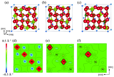 | ||
Fig. 2 Magnetization density isosurfaces for (a) the ideal Fd3m spinel phase, (b) the Imma 1![[thin space (1/6-em)]](https://www.rsc.org/images/entities/char_2009.gif) : :![[thin space (1/6-em)]](https://www.rsc.org/images/entities/char_2009.gif) 1 charge-ordered phase, and (c) the P4332 1 1 charge-ordered phase, and (c) the P4332 1![[thin space (1/6-em)]](https://www.rsc.org/images/entities/char_2009.gif) : :![[thin space (1/6-em)]](https://www.rsc.org/images/entities/char_2009.gif) 3 charge-ordered phase. Isosurfaces correspond to a charge density of 0.5 Å−3. (c), (d) and (e) show contour maps of the magnetization density within (010) NiO2 planes of the Fd3m, Imma and P4332 phases, respectively. 3 charge-ordered phase. Isosurfaces correspond to a charge density of 0.5 Å−3. (c), (d) and (e) show contour maps of the magnetization density within (010) NiO2 planes of the Fd3m, Imma and P4332 phases, respectively. | ||
In addition to the ferromagnetic states, we analysed antiferromagnetic states in the Imma and P4332 phases. Three antiferromagnetic 1![[thin space (1/6-em)]](https://www.rsc.org/images/entities/char_2009.gif) :
:![[thin space (1/6-em)]](https://www.rsc.org/images/entities/char_2009.gif) 1 CO states in the Imma phase could be identified, an shown in Fig. 3, which we label Types I, II and III. In Types I and II, antiferromagnetic interactions occur in the (001) plane. The difference between these models is the long-range interaction between Ni4+ planes. Type I consists of a long-range ferromagnetic interaction in the (100) and (010) planes, while in Type II all interactions between Ni3+ ions are antiferromagnetic. Type III interactions are the reverse of those in Type I. Interactions in the (001) plane are ferromagnetic, but the interactions within (100) and (010) planes are antiferromagnetic.
1 CO states in the Imma phase could be identified, an shown in Fig. 3, which we label Types I, II and III. In Types I and II, antiferromagnetic interactions occur in the (001) plane. The difference between these models is the long-range interaction between Ni4+ planes. Type I consists of a long-range ferromagnetic interaction in the (100) and (010) planes, while in Type II all interactions between Ni3+ ions are antiferromagnetic. Type III interactions are the reverse of those in Type I. Interactions in the (001) plane are ferromagnetic, but the interactions within (100) and (010) planes are antiferromagnetic.
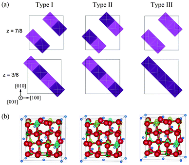 | ||
Fig. 3 Antiferromagnetic configurations within Ni3+ planes in the Imma 1![[thin space (1/6-em)]](https://www.rsc.org/images/entities/char_2009.gif) : :![[thin space (1/6-em)]](https://www.rsc.org/images/entities/char_2009.gif) 1 charge-ordered phase. Light and dark polyhedra represent the two spin states (up and down, respectively) of Ni3+ within NiO6 octahedra. (b) Magnetization density isosurfaces of 0.5 Å−3 for Type I, II and III configurations. Yellow and blue isosurfaces correspond to up and down spin components, respectively. 1 charge-ordered phase. Light and dark polyhedra represent the two spin states (up and down, respectively) of Ni3+ within NiO6 octahedra. (b) Magnetization density isosurfaces of 0.5 Å−3 for Type I, II and III configurations. Yellow and blue isosurfaces correspond to up and down spin components, respectively. | ||
Fig. 3 shows magnetization density isosurfaces calculated for these models. The patterns of magnetization coincide with the initial antiferromagnetic configurations. Total energies of Type I, II and III configurations are 179, 168 and 173 meV/f.u. lower than the ideal spinel phase, respectively. While the energy difference of 9 meV/f.u. between ferromagnetic Imma and antiferromagnetic Imma is very small, it indicates that the ferromagnetic Imma phase is more stable. This is in accordance with the Goodenough–Kanamori rule that the superexchange interaction of the 90° Ni–O–Ni linkage is weakly ferromagnetic.24,25 In the case of the P4332 CO phase, there is only one non-equivalent antiferromagnetic configuration for four Ni2+ ions in the unit cell, with the total energy of the antiferromagnetic phase −189 meV/f.u. lower than the ideal spinel phase. The total energy of the antiferromagnetic P4332 phase is only 1 meV/f.u. less than the ferromagnetic Imma and P4332 phases. Because this energy difference is quite small, and less than the accuracy of the present calculations, it is reasonable to conclude that the ferromagnetic Imma and ferro- and antiferromagnetic P4332 phases are equally stable.
To examine the influence of the magnitude of U on the energies obtained, we performed total energy calculations for various U values. Table 2 lists the total energy differences, ΔE, between the CO phases and ideal spinel phase for different values of U. Here ΔE is defined as ΔE = ECO − Espinel, where ECO is the total energy of the CO phase and Espinel is the total energy of the ideal spinel phase. A negative ΔE thus means that the CO phase is more stable than the ideal phase. The results in Table 2 confirm that ΔE depends on the value of U. However, the total energy differences for both the Imma CO phase and P4332 CO phase are negative and thus these phases are energetically favourable relative to the cubic spinel phase, regardless of the value of U. Similar calculations were carried out for other candidate structures, namely those of LiMn2O4 in space groups I41/amd26 and Fddd,27 AlV2O4 (space group R![[3 with combining macron]](https://www.rsc.org/images/entities/char_0033_0304.gif) m),28–30 and CuIr2S4 (space group P
m),28–30 and CuIr2S4 (space group P![[1 with combining macron]](https://www.rsc.org/images/entities/char_0031_0304.gif) ).31 In these cases, calculations were carried out assuming ferromagnetic states only. Comparison of the total energy differences for all these phases reveals that CO Imma and P4332 structures are always more stable than other CO spinel structures for the wide range of U values considered in this study.
).31 In these cases, calculations were carried out assuming ferromagnetic states only. Comparison of the total energy differences for all these phases reveals that CO Imma and P4332 structures are always more stable than other CO spinel structures for the wide range of U values considered in this study.
![[3 with combining macron]](https://www.rsc.org/images/entities/char_0033_0304.gif) m, and P
m, and P![[1 with combining macron]](https://www.rsc.org/images/entities/char_0031_0304.gif) are also given for comparison
are also given for comparison
| U (eV) | ΔE (meV/f.u.) | ||||||||
|---|---|---|---|---|---|---|---|---|---|
| Imma | Imma (AF type I) | P4332 | P4332 (AF) | Fddd | I41/amd |
R![[3 with combining macron]](https://www.rsc.org/images/entities/char_0033_0304.gif) ma ma |
R![[3 with combining macron]](https://www.rsc.org/images/entities/char_0033_0304.gif) mb mb |
P![[1 with combining macron]](https://www.rsc.org/images/entities/char_0031_0304.gif) |
|
| a Ref. 28, b Ref. 30. | |||||||||
| 0 | −23 | −20 | −2 | 3 | −3 | −5 | −1 | 1 | −14 |
| 1 | −84 | −82 | −44 | −44 | −54 | −49 | −6 | −5 | −36 |
| 3 | −205 | −203 | −176 | −177 | −157 | −140 | −32 | −33 | −145 |
| 5 | −242 | −238 | −239 | −239 | −194 | −181 | −63 | −60 | −179 |
| 6 | −188 | −179 | −188 | −189 | −148 | −140 | −5 | −2 | −126 |
| 7 | −79 | −58 | −71 | −61 | −62 | −61 | 133 | 121 | −32 |
Electronic structure
Fig. 4 shows plots of site-projected partial density of states (PDOS) obtained from the ideal spinel and ferromagnetic CO phases of LiNi2O4. In the ideal spinel phase, the topmost valence states are partially occupied and exhibit no gap. The electronic structure of the ideal spinel phase is thus metallic. In contrast, Imma and P4332 CO phases have a band gap, and are thus semiconductors. Energy states near the valence band top (VBT) and conduction band bottom (CBB) of the Imma phase are mainly composed of Ni3+ and O2– orbitals. In the P4332 phase, Ni2+ and Ni4+ orbitals overlap with O2– orbitals near the VBT and CBB, respectively. Energy states around the band gap are filled by up-spin components in both systems. Fig. 5 shows the band structure and lm-quantum-number-decomposed PDOS of Ni and O ions in the ferromagnetic Imma phase. The band structure was calculated using the primitive cell of the body-centred orthorhombic lattice. The VBT and CBB are located at the Γ point and W point, respectively, showing that the band gap of the Imma phase is indirect. Both band gap edges are filled by up-spin electrons, and the energy gap from the one-electron band energies is 0.36 eV.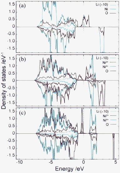 | ||
Fig. 4 Total and projected partial density of states for (a) Fd3m spinel, (b) 1![[thin space (1/6-em)]](https://www.rsc.org/images/entities/char_2009.gif) : :![[thin space (1/6-em)]](https://www.rsc.org/images/entities/char_2009.gif) 1 Imma charge-ordered, and (c) 1 1 Imma charge-ordered, and (c) 1![[thin space (1/6-em)]](https://www.rsc.org/images/entities/char_2009.gif) : :![[thin space (1/6-em)]](https://www.rsc.org/images/entities/char_2009.gif) 3 charge-ordered P4332 phases. Positive and negative represent the DOS of up-spin and down-spin, respectively. PDOS of Li are multiplied by 10. 3 charge-ordered P4332 phases. Positive and negative represent the DOS of up-spin and down-spin, respectively. PDOS of Li are multiplied by 10. | ||
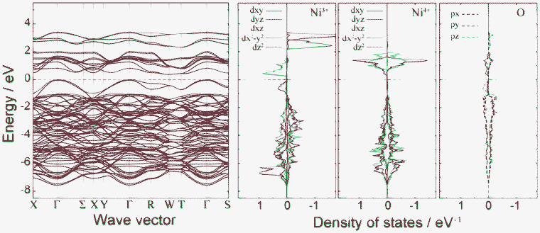 | ||
Fig. 5 Band structure and lm-decomposed partial density of states for Ni3+, Ni4+, and O2− ions in the 1![[thin space (1/6-em)]](https://www.rsc.org/images/entities/char_2009.gif) : :![[thin space (1/6-em)]](https://www.rsc.org/images/entities/char_2009.gif) 1 charge-ordered Imma phase. 1 charge-ordered Imma phase. | ||
After determining the locations of the VBT and CBB in terms of their k points, band-decomposed spin densities were obtained from the norms of the corresponding wave functions. Spatial distributions of spin densities within the pseudo-cubic spinel structure are shown in Fig. 6. The lm-decomposed PDOS and band-decomposed spin densities clearly show that the VBT is mainly composed of Ni3+ 3dz2 and O 2pz components. A small contribution is also made from O 2px and 2py orbitals. Such 3d–2p hybridization has previously been reported for NiO and LiNiO2 based on first-principles calculations.32–34 The CBB in the ferromagnetic Imma phase is composed of Ni3+ 3dx2−y2, O 2px and O 2py orbitals. In addition to up-spin, we also investigated the VBT and CBB of down-spin electrons, which we refer to as minor VBT and minor CBB, respectively. The minor VBT is composed almost exclusively from O 2pz, with little contribution from Ni 3d orbitals. The minor CBB consists of Ni4+ 3dz2 and O 2p orbitals. It should be noted that the band gap of the Imma phase results from splitting of the Ni3+ eg orbitals into 3dz2 and 3dx2−y2 due to Jahn–Teller (J–T) distortion.
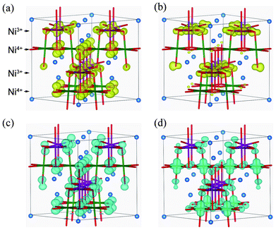 | ||
Fig. 6 Isosurfaces of band-decomposed charge densities in the 1![[thin space (1/6-em)]](https://www.rsc.org/images/entities/char_2009.gif) : :![[thin space (1/6-em)]](https://www.rsc.org/images/entities/char_2009.gif) 1 charge-ordered Imma phase: (a) valence band top levels, and (b) conduction band bottom levels, for up-spin electrons; and (c) valence band top levels, and (d) conduction band bottom levels of down-spin electrons. Isosurfaces correspond to 0.01 Å−3, with yellow and blue indicating up and down spin components, respectively. 1 charge-ordered Imma phase: (a) valence band top levels, and (b) conduction band bottom levels, for up-spin electrons; and (c) valence band top levels, and (d) conduction band bottom levels of down-spin electrons. Isosurfaces correspond to 0.01 Å−3, with yellow and blue indicating up and down spin components, respectively. | ||
The J–T distortion of the Imma phase can be clearly detected in the coordination environment of Ni ions, as evidenced by the different bond lengths and bond angles of NiO6 polyhedra in the Imma phase summarized in Table 3. For comparison, local structures of the ideal spinel phase are also listed. In the ideal spinel phase, the Wyckoff position of Ni is 16d, which has site symmetry ![[3 with combining macron]](https://www.rsc.org/images/entities/char_0033_0304.gif) m. The NiO6 polyhedra are slightly distorted, being elongated in the <111> direction, and with non-orthogonal O–Ni–O angles, but with all Ni–O bond lengths equal. In contrast, Ni sites in the 1
m. The NiO6 polyhedra are slightly distorted, being elongated in the <111> direction, and with non-orthogonal O–Ni–O angles, but with all Ni–O bond lengths equal. In contrast, Ni sites in the 1![[thin space (1/6-em)]](https://www.rsc.org/images/entities/char_2009.gif) :
:![[thin space (1/6-em)]](https://www.rsc.org/images/entities/char_2009.gif) 1 CO Imma phase are of lower symmetry. As shown in Table 3, Ni3+–O bond lengths exhibit clear anisotropy, especially for Ni3+; Ni3+–O bonds in the c direction are 9.9% longer than those in the ab plane. This J–T distortion is a result of the partial occupation of the eg orbital of Ni3+. Elongation of Ni3+–O bonds along the c axis reduces repulsive interactions between the electron-occupied eg orbital and oxide ions in this direction, and thus stabilizes the 3dz2 orbital over the 3dx2−y2 orbital, as seen in the PDOS of Fig. 5. This stabilization of the 3dz2 orbital by J–T distortion results in the Imma CO phase being more stable than the ideal spinel phase. Ni4+–O bond lengths are shorter than those of Ni3.5+–O in the ideal spinel and Ni3+–O in the Imma phase, consistent with the smaller ionic size of the Ni4+ ion. Compared to Ni3+-containing octahedra, the local distortion around Ni4+ ions is smaller. All Ni4+–O bond lengths are almost the same, indicating no J–T distortion. This is because the eg orbitals of Ni4+ ions are unoccupied.
1 CO Imma phase are of lower symmetry. As shown in Table 3, Ni3+–O bond lengths exhibit clear anisotropy, especially for Ni3+; Ni3+–O bonds in the c direction are 9.9% longer than those in the ab plane. This J–T distortion is a result of the partial occupation of the eg orbital of Ni3+. Elongation of Ni3+–O bonds along the c axis reduces repulsive interactions between the electron-occupied eg orbital and oxide ions in this direction, and thus stabilizes the 3dz2 orbital over the 3dx2−y2 orbital, as seen in the PDOS of Fig. 5. This stabilization of the 3dz2 orbital by J–T distortion results in the Imma CO phase being more stable than the ideal spinel phase. Ni4+–O bond lengths are shorter than those of Ni3.5+–O in the ideal spinel and Ni3+–O in the Imma phase, consistent with the smaller ionic size of the Ni4+ ion. Compared to Ni3+-containing octahedra, the local distortion around Ni4+ ions is smaller. All Ni4+–O bond lengths are almost the same, indicating no J–T distortion. This is because the eg orbitals of Ni4+ ions are unoccupied.
Fd![[3 with combining macron]](https://www.rsc.org/images/entities/char_0033_0304.gif) m m |
Imma | P4332 | |||
|---|---|---|---|---|---|
| Ni–O (Å) | 1.937 × 6 | 3+ | 1.907 × 4 (ab-plane) | 2+ | 2.062 × 6 |
| 2.096 × 2 (c-axis) | |||||
| 4+ | 1.882 × 4 (ab-plane) | 4+ | 1.868 × 2 | ||
| 1.886 × 2 (c-axis) | 1.879 × 2 | ||||
| 1.895 × 2 | |||||
| O–Ni–O (deg) | 3+ | 83.1 × 2 | 2+ | 78.8 × 6 | |
| 96.9 × 2 | 99.4 × 3 | ||||
| 80.1 × 4 | 103.2 × 3 | ||||
| 83.5 × 6 | 99.9 × 4 | ||||
| 96.5 × 6 | 4+ | 83.0 × 2 | 4+ | 82.8 × 2 | |
| 97.0 × 2 | 83.1 × 2 | ||||
| 86.5 × 4 | 88.6 × 2 | ||||
| 93.5 × 4 | 94.1 × 2 | ||||
| 94.6 × 2 | |||||
| 95.4 | |||||
| 98.5 |
Fig. 7 shows the band structure and lm-quantum-number-decomposed PDOS of Ni and O ions in the ferromagnetic P4332 phase. The VBT and CBB are located at the M point and Γ point, respectively, so that the P4332 phase has an indirect band gap, just as with the Imma phase. Both band gap edges comprise up-spin components. The energy gap between one-electron band energies is 0.87 eV, which is larger than that for the Imma phase. Fig. 8 shows the spatial distribution of band-decomposed spin densities originating from the VBT and CBB of up and down spins in the P4332 phase. The lm-decomposed PDOS and the spin density isosurfaces clearly show that the VBT is mainly composed of the eg orbitals, 3dz2 and 3dx2−y2, of Ni2+ ions.
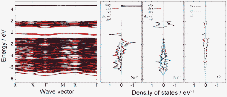 | ||
Fig. 7 Band structure and lm-decomposed partial density of states of Ni2+, Ni4+, and O2− ions for the 1![[thin space (1/6-em)]](https://www.rsc.org/images/entities/char_2009.gif) : :![[thin space (1/6-em)]](https://www.rsc.org/images/entities/char_2009.gif) 3 charge-ordered P4332 phase. 3 charge-ordered P4332 phase. | ||
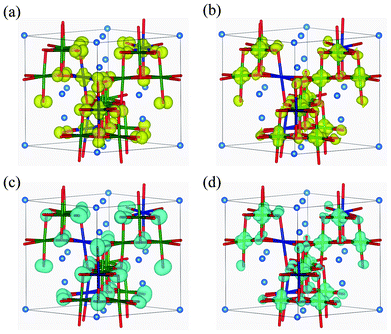 | ||
Fig. 8 Isosurfaces of band-decomposed charge densities in the 1![[thin space (1/6-em)]](https://www.rsc.org/images/entities/char_2009.gif) : :![[thin space (1/6-em)]](https://www.rsc.org/images/entities/char_2009.gif) 3 charge-ordered P4332 phase: (a) valence band top levels, and (b) conduction band bottom levels, for up-spin electrons; and (c) valence band top levels, and (d) conduction band bottom levels, for down-spin electrons. Isosurfaces correspond to 0.01 Å−3, with yellow and blue indicating up and down spin components, respectively. 3 charge-ordered P4332 phase: (a) valence band top levels, and (b) conduction band bottom levels, for up-spin electrons; and (c) valence band top levels, and (d) conduction band bottom levels, for down-spin electrons. Isosurfaces correspond to 0.01 Å−3, with yellow and blue indicating up and down spin components, respectively. | ||
Hybridization of Ni 3d with O 2p orbitals is also noticeable from the PDOS. This is the same overlapping as occurred in the Imma phase. As seen in Fig. 7 and 8, the VBT bands of the Ni2+ eg orbitals hybridized with O 2p orbitals are strongly localized. The greater stability of the P4332 CO phase compared to the ideal spinel phase, which has metallic and delocalized valence states, can be attributed to the localization of Ni 3d electrons. The CBB is composed of Ni4+ eg orbitals and O 2p orbitals. Similar to the Imma phase, the minor VBT is principally composed of O 2p orbitals. Ni4+ eg and O 2p orbitals constitute the minor CBB.
The coordination environments of Ni ions in the P4332 phase are also summarized in Table 3. Ni2+O6 octahedra show no J–T distortion because the eg orbitals of the up-spin component are fully occupied. All bond lengths of Ni2+–O are thus the same. The Ni2+–O bond is longer than the Ni3+–O and Ni4+–O bonds because of the larger ionic radius of Ni2+. Ni4+O6 octahedra are more distorted, but the Ni4+–O bond lengths and O–Ni4+–O angles are similar to those of Ni4+O6 in the Imma phases, even though the Ni4+ site (12d), with ..2 site symmetry, has lower symmetry than the Ni4+ site in the Imma phase (4a with site symmetry 2/m).
The above results suggest that the ground-state structure of spinel-type LiNi2O4 is charge ordered with a characteristic electronic structure. Fig. 9 shows schematic diagrams of the bonding states in the ferromagnetic 1![[thin space (1/6-em)]](https://www.rsc.org/images/entities/char_2009.gif) :
:![[thin space (1/6-em)]](https://www.rsc.org/images/entities/char_2009.gif) 1 CO Imma and 1
1 CO Imma and 1![[thin space (1/6-em)]](https://www.rsc.org/images/entities/char_2009.gif) :
:![[thin space (1/6-em)]](https://www.rsc.org/images/entities/char_2009.gif) 3 CO P4332 phases. In both cases, mixing between the 3d orbitals of divalent or trivalent Ni ions and the 2p orbitals of O ions are clearly observed at the VBT. A similar phenomenon is characteristic to NiO.32–34 In the case of the CBB, in both the Imma and P4332 phases it is composed of Ni3+ 3dx2−y2 and Ni4+ eg orbitals. These Ni 3d orbitals also hybridize with O 2p orbitals. The band gap of CO LiNi2O4 is neither a pure Mott–Hubbard type nor a charge-transfer type, and can be regarded as an intermediate type. On the other hand, the minor band gap is of a typical charge-transfer type in both phases. The two characteristic electronic structures thus coexist in ferromagnetic LiNi2O4.
3 CO P4332 phases. In both cases, mixing between the 3d orbitals of divalent or trivalent Ni ions and the 2p orbitals of O ions are clearly observed at the VBT. A similar phenomenon is characteristic to NiO.32–34 In the case of the CBB, in both the Imma and P4332 phases it is composed of Ni3+ 3dx2−y2 and Ni4+ eg orbitals. These Ni 3d orbitals also hybridize with O 2p orbitals. The band gap of CO LiNi2O4 is neither a pure Mott–Hubbard type nor a charge-transfer type, and can be regarded as an intermediate type. On the other hand, the minor band gap is of a typical charge-transfer type in both phases. The two characteristic electronic structures thus coexist in ferromagnetic LiNi2O4.
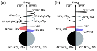 | ||
Fig. 9 Schematic diagrams of bonding states of ferromagnetic (a) 1![[thin space (1/6-em)]](https://www.rsc.org/images/entities/char_2009.gif) : :![[thin space (1/6-em)]](https://www.rsc.org/images/entities/char_2009.gif) 1 CO Imma phase, and (b) 1 1 CO Imma phase, and (b) 1![[thin space (1/6-em)]](https://www.rsc.org/images/entities/char_2009.gif) : :![[thin space (1/6-em)]](https://www.rsc.org/images/entities/char_2009.gif) 3 CO P4332 phase, of LiNi2O4. 3 CO P4332 phase, of LiNi2O4. | ||
Heat of transformation for the layered-to-spinel transition
The above calculations indicate that charge ordering needs to be taken into account when determining the stable state of spinel-type LiNi2O4. Consequently, quantitative evaluation of the heat of transformation (ΔH) from the layered to the spinel form should be based on a charge-ordered structure for spinel-type LiNi2O4. For convenience, in what follows we refer to the layered structure as Li0.5NiO2, and to the spinel-type structure as LiNi2O4. We calculated ΔH from the total energies of these two phases, using the total energy of the Imma 1![[thin space (1/6-em)]](https://www.rsc.org/images/entities/char_2009.gif) :
:![[thin space (1/6-em)]](https://www.rsc.org/images/entities/char_2009.gif) 1 CO spinel-type phase for LiNi2O4, and that of Li0.5NiO2 with a monoclinic structure in space group C2/m reported previously.2,4,5,35 In the latter structure, Li ions are located on 2d sites, with fractional coordinates of (1/2, 0, 1/2) and (0, 1/2, 1/2), and occupancy of 0.5. Because the Li sites are partially occupied, we considered two models for monoclinic Li0.5NiO2, one with the Li ion on the (1/2, 0, 1/2) site, and one with the Li ion on the (0, 1/2, 1/2) site. This vacancy ordering leads to a change in space group from C2/m (a base-centred monoclinic lattice) to P2/m (a primitive monoclinic lattice). Geometry optimization of the monoclinic Li0.5NiO2 was carried out using the same conditions as for spinel LiNi2O4. The value of U used for Ni 3d was 6 eV.
1 CO spinel-type phase for LiNi2O4, and that of Li0.5NiO2 with a monoclinic structure in space group C2/m reported previously.2,4,5,35 In the latter structure, Li ions are located on 2d sites, with fractional coordinates of (1/2, 0, 1/2) and (0, 1/2, 1/2), and occupancy of 0.5. Because the Li sites are partially occupied, we considered two models for monoclinic Li0.5NiO2, one with the Li ion on the (1/2, 0, 1/2) site, and one with the Li ion on the (0, 1/2, 1/2) site. This vacancy ordering leads to a change in space group from C2/m (a base-centred monoclinic lattice) to P2/m (a primitive monoclinic lattice). Geometry optimization of the monoclinic Li0.5NiO2 was carried out using the same conditions as for spinel LiNi2O4. The value of U used for Ni 3d was 6 eV.
Table 4 shows the optimized lattice constants of monoclinic Li0.5NiO2 together with experimental data.5 The lattice constants are well reproduced, with errors of less than 1% compared to experiment. The differences in structure and Li positions are negligible. In the same manner as for spinel LiNi2O4, Δρ↑↓ was calculated for layered Li0.5NiO2. As shown in Fig. 10, Ni ions within the same (100) plane as Li ions become non-magnetic Ni4+ ions in both Li0.5NiO2 models, indicating that charge ordering also occurs in layered Li0.5NiO2. The energy difference between the two monoclinic unit cell models is only about 0.05 meV per Li0.5NiO2 formula unit. It can thus be concluded that the choice of occupancy of the Li site hardly affects the energy state of monoclinic Li0.5NiO2. Next we constructed a 2 × 2 × 2 supercell of monoclinic Li0.5NiO2. This supercell contained 56 atoms, equal to the number of atoms in the spinel-type conventional cell. The total energy of the supercell was calculated using a k-mesh size of 3 × 4 × 3.
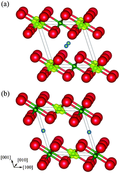 | ||
| Fig. 10 Magnetization density isosurfaces (yellow) of layer-type monoclinic Li0.5NiO2 with the Li ion at fractional coordinates (a) (1/2, 0, 1/2), and (b) (0, 1/2, 1/2). Isosurfaces correspond to 0.5 Å−3. | ||
| Calc. (S.G. P2/m) | Exp. (S.G. C2/m)a | |||||
|---|---|---|---|---|---|---|
| a Ref. 5: Composition of the sample is Li0.49Ni1.01O2. | ||||||
| a (Å) | 5.000 | 5.000 | 4.9635 | |||
| b (Å) | 2.815 | 2.815 | 2.8304 | |||
| c (Å) | 5.122 | 5.124 | 5.0769 | |||
| β (deg.) | 108.78 | 108.76 | 109.513 | |||
| V (Å3/LiNi2O4) | 68.33 | 68.29 | 67.227 | |||
| Li | 1g | (1/2, 0, 1/2) | 1g | (0, 1/2, 1/2) | 2d | (0, 1/2, 1/2) |
| Ni | 1a | (0, 0, 0) (3+) | 1a | (0, 0, 0) (4+) | 2a | (0, 0, 0) |
| 1e | (1/2, 1/2, 0) (4+) | 1e | 1e (1/2, 1/2, 0) (3+) | |||
| O | 2m | (0.294, 0, 0.785) | 2m | (0.256, 0, 0.802) | 4i | (0.2632, 0, 0.7899) |
| 2n | (0.756, 1/2, 0.802) | 2n | (0.794, 1/2, 0.785) | |||
The total energies obtained in this manner produce a heat of transformation, ΔH, of 122 meV per Li0.5NiO2 formula unit, equal to 125 J g−1. Lee et al.10 reported a value of about 100 J g−1 for ΔH from differential scanning calorimetry measurements. The 20% difference between our DFT result and the experimental value may be due to several factors. First, the present calculations are based on general DFT, and temperature effects like lattice vibration are not taken into account. Second, Li and vacancy ordering was limited to the size of the monoclinic unit cell of Li0.5NiO2, and it is possible that larger-scale ordering is important. In addition, LixNiO2 systems are known to have a small amount of disorder (cation-antisite or cation-interchange defects) between Li and Ni sites. The effect of such cation disorder is not taken into account in our study. However, it should be noted that the energy level of the error is around 10 meV/f.u. Finally, an experimental error of around 5% is also typical.
Given the above considerations, our result is of the correct order, with reasonable accuracy considering its derivation from first principles. If ΔH is calculated without any charge ordering in the spinel-type LiNi2O4 phase, in other words if the total energy of the ideal spinel phase is used, the value of ΔH decreases to only 28 meV/f.u., i.e. 28 J g−1, in which case the discrepancy between experimental and theoretical values is much worse. Our results thus demonstrate that charge ordering is an important factor that cannot be ignored when quantitatively analysing the layer-to-spinel transformation in the LixNiO2 system.
Conclusions
The energy states and electronic structures of charge-ordered and charge-disordered spinel-type LiNi2O4 structures were calculated within a DFT+U framework. The results revealed that the Imma 1![[thin space (1/6-em)]](https://www.rsc.org/images/entities/char_2009.gif) :
:![[thin space (1/6-em)]](https://www.rsc.org/images/entities/char_2009.gif) 1 CO phase and P4332 1
1 CO phase and P4332 1![[thin space (1/6-em)]](https://www.rsc.org/images/entities/char_2009.gif) :
:![[thin space (1/6-em)]](https://www.rsc.org/images/entities/char_2009.gif) 3 CO phase are more stable than the ideal spinel phase with a uniform electronic charge distribution. We also calculated the total energies of LiNi2O4 with other hypothetical spinel-type CO compounds, and found that the Imma and P4332 phases are energetically more favourable, regardless of the value of the Hubbard U parameter. The Imma and P4332 phases are thus the strongest candidates for being the most stable (ground-state) structures of LiNi2O4.
3 CO phase are more stable than the ideal spinel phase with a uniform electronic charge distribution. We also calculated the total energies of LiNi2O4 with other hypothetical spinel-type CO compounds, and found that the Imma and P4332 phases are energetically more favourable, regardless of the value of the Hubbard U parameter. The Imma and P4332 phases are thus the strongest candidates for being the most stable (ground-state) structures of LiNi2O4.
Analysis of the electronic structures revealed that hybridization between Ni 3d and O 2p orbitals occurs in LiNi2O4, similar to the bonding character in rock-salt NiO. The band gap of ferromagnetic LiNi2O4 is found to be of “intermediate” type, i.e., neither a pure Mott–Hubbard nor charge-transfer type. The band gap of the Imma phase is formed between Ni3+3dz2–O2p orbitals constituting the valence band top and Ni3+3dx2−y2–O2p orbitals in the conduction band bottom. Splitting of the eg orbitals of Ni3+ ions resulting from Jahn–Teller distortion was also observed. In the P4332 phase, the valence band top comprises Ni2+ 3d eg–O2p orbitals and the conduction band bottom Ni4+ 3d eg–O2p.
Our results indicate that charge ordering is an important process in stabilizing the spinel phase of LiNi2O4, and needs to be included to calculate reliably the electronic structure and the relative thermal stability of the spinel phase compared with the layered phase. When charge ordering is included, DFT calculations reproduce the heat of transformation from layered to spinel structures with improved accuracy, whereas when charge ordering is ignored the heat of transformation is significantly underestimated.
Acknowledgements
A part of this study was supported by Japan Society for the Promotion of Science (JSPS) through its “Funding Program for World-Leading Innovative R&D on Science and Technology (FIRST Program)”.References
- L. D. Dyer, B. S. Borie and G. P. Smith, J. Am. Chem. Soc., 1954, 76, 1499–1503 CrossRef CAS.
- A. Hirano, R. Kanno, Y. Kawamoto, Y. Takeda, K. Yamaura, M. Takano, K. Ohyama, M. Ohashi and Y. Yamaguchi, Solid State Ionics, 1995, 78, 123–131 CrossRef CAS.
- K. Mukai, J. Sugiyama and Y. Aoki, J. Solid State Chem., 2010, 183, 1726–1732 Search PubMed.
- H. Arai, S. Okada, H. Ohtsuka, M. Ichimura and J. Yamaki, Solid State Ionics, 1995, 80, 261–269 CrossRef CAS.
- A. Hirano, R. Kanno, Y. Kawamoto, K. Oikawa, T. Kamiyama and F. Izumi, Solid State Ionics, 1996, 86–88, 791–796 Search PubMed.
- J. P. Peres, F. Weill and C. Delmas, Solid State Ionics, 1999, 116, 19–27 CrossRef CAS.
- M. E. Arroyo y de Dompablo, A. Van der Ven and G. Ceder, Phys. Rev. B: Condens. Matter, 2002, 66, 064112 CrossRef.
- M. E. Arroyo y de Dompablo and G. Ceder, Chem. Mater., 2003, 15, 63–67 CrossRef.
- H. Arai, S. Okada, Y. Sakurai and J. Yamaki, Solid State Ionics, 1998, 109, 295–302 CrossRef CAS.
- K. K. Lee, W. S. Yoon, K. B. Kim, K. Y. Lee and S. T. Hong, J. Electrochem. Soc., 2001, 148, A716–A722 Search PubMed.
- M. Guilmard, L. Croguennec, D. Denux and C. Delmas, Chem. Mater., 2003, 15, 4476–4483 CrossRef CAS.
- M. G. S. R. Thomas, W. I. F. David, J. B. Goodenough and P. Groves, Mater. Res. Bull., 1985, 20, 1137–1146 CrossRef CAS.
- C. Chazel, M. Ménétrier, D. Carlier, L. Croguennec and C. Delmas, Chem. Mater., 2007, 19, 4166–4173 Search PubMed.
- L. Wang, T. Maxisch and G. Ceder, Chem. Mater., 2007, 19, 543–552 CrossRef CAS.
- A. Kuwabara, C. A. J. Fisher, R. Huang, Y. H. Ikuhara, H. Moriwake, Y. Ikuhara and H. Oki, AMTC Lett., 2010, 2, 200–201 Search PubMed.
- G. Kresse and D. Joubert, Phys. Rev. B: Condens. Matter Mater. Phys., 1998, 59, 1758–1775.
- J. P. Perdew, K. Burke and M. Ernzerhof, Phys. Rev. Lett., 1996, 77, 3865–3868 CrossRef CAS.
- G. Kresse and J. Furthmüller, Phys. Rev. B: Condens. Matter, 1996, 54, 11169–11186 CrossRef CAS.
- S. L. Dudarev, G. A. Botton, S. Y. Savrasov, C. J. Humphreys and A. P. Sutton, Phys. Rev. B: Condens. Matter Mater. Phys., 1998, 57, 1505–1509 CrossRef CAS.
- K. Momma and F. Izumi, J. Appl. Crystallogr., 2011, 44, 1272–1276 CrossRef CAS.
- M. A. Lafontaine, M. le Blanc and G. Ferey, Acta Crystallogr., Sect. C: Cryst. Struct. Commun., 1989, 45, 1205–1206 CrossRef.
- K. Ariyoshi, Y. Iwakoshi, N. Nakayama and T. Ohzuku, J. Electrochem. Soc., 2004, 151, A296–A303 CrossRef CAS.
- G. Q. Liu, L. Wen and Y. M. Liu, J. Solid State Electrochem., 2010, 14, 2191–2202 CrossRef CAS.
- J. B. Goodenough, J. Phys. Chem. Solids, 1958, 6, 287–297 CrossRef CAS.
- J. Kanamori, J. Phys. Chem. Solids, 1959, 10, 87–98 CrossRef CAS.
- A. S. Wills, N. P. Raju and J. E. Greedan, Chem. Mater., 1999, 11, 1510–1518 CrossRef CAS.
- J. Rodríguez-Carvajal, G. Rousse; C. Masquelier and M. Hervieu, Phys. Rev. Lett., 1998, 81, 4660–4663 CrossRef CAS.
- K. Matsuno, T. Katsufuji, S. Mori, Y. Moritomo, A. Machida, E. Nishibori, M. Takata, N. Sakata, M. Yamamoto and H. Takagi, J. Phys. Soc. Jpn., 2001, 70, 1456–1459 Search PubMed.
- K. Matsuno, T. Katsufuji, S. Mori, A. Machida, Y. Moritomo, K. Kato, E. Nishibori, M. Takata, M. Sakata, K. Kitazawa and H. Takagi, Phys. Rev. Lett., 2003, 90, 096404 Search PubMed.
- Y. Horibe, M. Shingu, K. Kurushima, H. Ishibashi, N. Ikeda, K. Kato, Y. Motome, N. Furukawa, S. Mori and T. Katsufuji, Phys. Rev. Lett., 2006, 96, 086406 Search PubMed.
- P. G. Radaelli, Y. Horibe, M. J. Gutmann, H. Ishibashi, C. H. Chen, R. M. Ibberson, Y. Koyama, Y.-S. Hor, V. Kiryukhin and S.-W. Cheong, Nature, 2002, 416, 155–158 CrossRef CAS.
- A. Fujimori and F. Minami, Phys. Rev. B, 1984, 30, 957–970 CrossRef CAS.
- J. Zaanen, G. A. Sawatzky and J. W. Allen, Phys. Rev. Lett., 1985, 55, 418–421 CrossRef CAS.
- V. I. Anisimov, J. Zaanen and O. K. Andersen, Phys. Rev. B: Condens. Matter, 1991, 44, 943–953 CrossRef CAS.
- C. Pouillerie, E. Suard and C. Delmas, J. Solid State Chem., 2001, 158, 187–197 Search PubMed.
| This journal is © The Royal Society of Chemistry 2012 |
